Page 458 of 524
2. Check the fluid level in each cell. If it is
necessary to add fluid, add only distilled
water to bring the level up to the bottom of
the filler opening.Do not overfill.Reinstall
the vent caps.Vehicles operated in high temperatures or under
severe conditions require frequent checks of the
battery fluid level.
JUMP STARTING
If jump starting is necessary, refer to “Jump start-
ing” in the “In case of emergency” section of this
manual for additional information. If the engine
does not start by jump starting, the battery may
have to be replaced. Contact a NISSAN dealer.
1. Super charger pulley
2. Idler pulley
3. Water pump pulley
4 Air conditioner compressor pulley
5. Drive belt automatic tensioner pulley
6. Crankshaft pulley
WARNING
Be sure the ignition key is in the OFF or
LOCK position before servicing drive belt.
The engine could rotate unexpectedly.
LDI0302
LDI2480
DRIVE BELT
Maintenance and do-it-yourself8-17
Page 459 of 524

1. Visually inspect the belt for signs of unusual
wear, cuts, fraying or looseness. If the belt is
in poor condition or is loose, have it replaced
or adjusted by a NISSAN dealer.
2. Have the belt checked regularly for condi-
tion and tension in accordance with the
maintenance schedule found in your
“NISSAN Service and Maintenance Guide”.
REPLACING SPARK PLUGS
Iridium-tipped spark plugs
It is not necessary to replace iridium-tipped�A
spark plugs as frequently as conventional type
spark plugs because they last much longer. Fol-
low the maintenance log shown in the “NISSAN
Service and Maintenance Guide”. Do not service
iridium-tipped spark plugs by cleaning or regap-
ping.
●Always replace spark plugs with rec-
ommended or equivalent ones.
WARNING
Be sure the engine and ignition switch are
off and that the parking brake is engaged
securely.
CAUTION
Be sure to use the correct socket to re-
move the spark plugs. An incorrect socket
can damage the spark plugs.
If replacement is required, see your NISSAN
dealer for assistance.
SDI1895
SPARK PLUGS
8-18Maintenance and do-it-yourself
Page 463 of 524

Proper brake inspection intervals should
be followed.For additional information regard-
ing brake inspections, refer to the appropriate
maintenance schedule information in the
“NISSAN Service and Maintenance Guide”.
ENGINE COMPARTMENT
CAUTION
Never use a fuse of a higher or lower
amperage rating than specified on the
fuse box cover. This could damage the
electrical system or cause a fire.
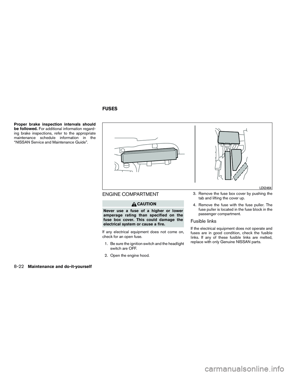
If any electrical equipment does not come on,
check for an open fuse.
1. Be sure the ignition switch and the headlight
switch are OFF.
2. Open the engine hood.3. Remove the fuse box cover by pushing the
tab and lifting the cover up.
4. Remove the fuse with the fuse puller. The
fuse puller is located in the fuse block in the
passenger compartment.
Fusible links
If the electrical equipment does not operate and
fuses are in good condition, check the fusible
links. If any of these fusible links are melted,
replace with only Genuine NISSAN parts.
LDI2464
FUSES
8-22Maintenance and do-it-yourself
Page 464 of 524

PASSENGER COMPARTMENT
CAUTION
Never use a fuse of a higher or lower
amperage rating than specified on the
fuse box cover. This could damage the
electrical system or cause a fire.
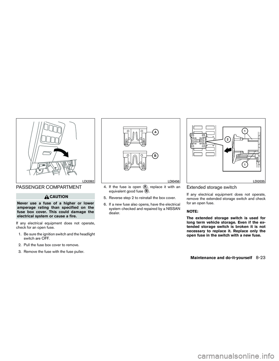
If any electrical equipment does not operate,
check for an open fuse.
1. Be sure the ignition switch and the headlight
switch are OFF.
2. Pull the fuse box cover to remove.
3. Remove the fuse with the fuse puller.4. If the fuse is open
�A, replace it with an
equivalent good fuse
�B.
5. Reverse step 2 to reinstall the box cover.
6. If a new fuse also opens, have the electrical
system checked and repaired by a NISSAN
dealer.Extended storage switch
If any electrical equipment does not operate,
remove the extended storage switch and check
for an open fuse.
NOTE:
The extended storage switch is used for
long term vehicle storage. Even if the ex-
tended storage switch is broken it is not
necessary to replace it. Replace only the
open fuse in the switch with a new fuse.
LDI2092LDI0456LDI2035
Maintenance and do-it-yourself8-23
Page 465 of 524
How to remove the extended storage
switch:
1. To remove the extended storage switch, be
sure the ignition switch is in the OFF or
LOCK position.
2. Be sure the headlight switch is in the OFF
position.
3. Remove the fuse box cover.
4. Pinch the locking tabs
�1found on each
side of the storage switch.
5. Pull the storage switch straight out from the
fuse box
�2.
CAUTION
Be careful not to allow children to swallow
the battery or removed parts.
SDI1867
BATTERY REPLACEMENT
8-24Maintenance and do-it-yourself
Page 488 of 524

●If a methanol blend is used, it should
contain no more than 5% methanol
(methyl alcohol, wood alcohol) . It
should also contain a suitable amount
of appropriate cosolvents and corro-
sion inhibitors. If not properly formu-
lated with appropriate cosolvents and
corrosion inhibitors, such methanol
blends may cause fuel system damage
and/or vehicle performance problems.
At this time, sufficient data is not avail-
able to ensure that all methanol blends
are suitable for use in NISSAN ve-
hicles.
If any driveability problems such as engine stall-
ing and difficult hot-starting are experienced after
using oxygenate-blend fuels, immediately
change to a non-oxygenate fuel or a fuel with a
low blend of MTBE.
Take care not to spill gasoline during refu-
eling. Gasoline containing oxygenates can
cause paint damage.
E–15 fuel
E-15 fuel is a mixture of approximately 15% fuel
ethanol and 85% unleaded gasoline. E-15 can
only be used in vehicles designed to run on E-15
fuel. Do not use E-15 in your vehicle. U.S. gov-
ernment regulations require fuel ethanol dispens-
ing pumps to be identified with small, square,orange and black label with the common abbre-
viation or the appropriate percentage for that
region.
E–85 fuel
E-85 fuel is a mixture of approximately 85% fuel
ethanol and 15% unleaded gasoline. E-85 can
only be used in a Flexible Fuel Vehicle (FFV) . Do
not use E-85 in your vehicle. U.S. government
regulations require fuel ethanol dispensing
pumps to be identified by a small, square, orange
and black label with the common abbreviation or
the appropriate percentage for that region.
Aftermarket fuel additives
NISSAN does not recommend the use of any
aftermarket fuel additives (for example, fuel injec-
tor cleaner, octane booster, intake valve deposit
removers, etc.) which are sold commercially.
Many of these additives intended for gum, varnish
or deposit removal may contain active solvents or
similar ingredients that can be harmful to the fuel
system and engine.
Octane rating tips
Using unleaded gasoline with an octane
rating lower than recommended can cause
persistent, heavy “spark knock.” (“Spark
knock” is a metallic rapping noise.) If se-
vere, this can lead to engine damage. If youdetect a persistent heavy spark knock even
when using gasoline of the stated octane
rating, or if you hear steady spark knock
while holding a steady speed on level
roads, have a NISSAN dealer correct the
condition. Failure to correct the condition
is misuse of the vehicle, for which NISSAN
is not responsible.
Incorrect ignition timing may result in spark
knock, after-run and/or overheating, which may
cause excessive fuel consumption or engine
damage. If any of the above symptoms are en-
countered, have your vehicle checked at a
NISSAN dealer.
However, now and then you may notice
light spark knock for a short time while
accelerating or driving up hills. This is not a
cause for concern, because you get the
greatest fuel benefit when there is light
spark knock for a short time under heavy
engine load.
Technical and consumer information9-5
Page 491 of 524
ENGINE
ModelQR25DER
TypeGasoline, 4-cycle, DOHC
Cylinder arrangement4-cylinder in-line
Bore x Strokein (mm) 3.5 x 3.9 (89.0 x 100.0)
Displacementcu in (cm
3) 151.82 (2,488)
Firing order1–3–4–2
Idle speed
No adjustment is necessary. CVT (in “N” position)
Ignition timing (degree B.T.D.C. at idle speed)
CO%atidle
Spark plugDILKAR7C9H
Spark plug gap (Nominal)in (mm) 0.035 (0.9)
Camshaft operationTiming chain
This spark ignition system complies with the Canadian standard ICES-002.
SPECIFICATIONS
9-8Technical and consumer information
Page 505 of 524

A weight-distributing hitch system (Class IV) is
recommended if you plan to tow trailers with a
maximum weight over 5,000 lbs (2,268 kg).
Check with the trailer and towing equipment
manufacturers to determine if they recommend
the use of a weight-distributing hitch system.
NOTE:
A weight-distributing hitch system may af-
fect the operation of trailer surge brakes. If
you are considering use of a weight-
distributing hitch system with a surge
brake-equipped trailer, check with the
surge brake, hitch or trailer manufacturer
to determine if and how this can be done.
Follow the instructions provided by the manufac-
turer for installing and using the weight-
distributing hitch system.
General set-up instructions are as follows:
1. Park unloaded vehicle on a level surface.
With the ignition on and the doors closed,
allow the vehicle to stand for several minutes
so that it can level.
2. Measure the height of a reference point on
the front and rear bumpers at the center of
the vehicle.3. Attach the trailer to the vehicle and adjust
the hitch equalizers so that the front bumper
height is within0-.5inches (0 – 13 mm) of
the reference height measured in step 2. The
rear bumper should be no higher than the
reference height measured in step 2.
WARNING
Properly adjust the weight distributing
hitch so the rear of the bumper is no
higher than the measured reference
height when the trailer is attached. If the
rear bumper is higher than the measured
reference height when loaded, the vehicle
may handle unpredictably which could
cause a loss of vehicle control and cause
serious personal injury or property
damage.
Sway control device
Sudden maneuvers, wind gusts, and buffeting
caused by other vehicles can affect trailer han-
dling. Sway control devices may be used to help
control these affects. If you choose to use one,
contact a reputable trailer hitch supplier to make
sure the sway control device will work with the
vehicle, hitch, trailer and the trailer’s brake sys-
tem. Follow the instructions provided by the
manufacturer for installing and using the sway
control device.
Class I hitch
Class I trailer hitch equipment (receiver, ball
mount and hitch ball) can be used to tow trailers
of a maximum weight of 2,000 lb (907 kg) .
Class II hitch
Class II trailer hitch equipment (receiver, ball
mount and hitch ball) can be used to tow trailers
of a maximum weight of 3,500 lb (1,587 kg).
Class III hitch
Class III trailer hitch equipment (receiver, ball
mount and hitch ball) can be used to tow trailers
of a maximum weight of 5,000 lb (2,268 kg).
Tire pressures
●When towing a trailer, inflate the ve-
hicle tires to the recommended cold
tire pressure indicated on the tire
placard.
●Trailer tire condition, size, load rating
and proper inflation pressure should
be in accordance with the trailer and
tire manufacturer’s specifications.
9-22
Technical and consumer information