2015 NISSAN MURANO PLATINUM weight
[x] Cancel search: weightPage 50 of 424
●If the child restraint is compatible with your
vehicle, place your child in the child restraint
and check the various adjustments to be
sure the child restraint is compatible with
your child. Choose a child restraint that is
designed for your child’s height and weight.
Always follow all recommended procedures.
● If the combined weight of the child and child
restraint is less than 65 lbs (29.5 kg) , you
may use either the LATCH anchors or the
seat belt to install the child restraint (not both
at the same time) .
● If the combined weight of the child and child
restraint is greater than 65 lbs (29.5 kg) , use
the vehicle’s seat belt (not the lower an-
chors) to install the child restraint.
● Be sure to follow the child restraint manufac-
turer’s instructions for installation.
All U.S. states and Canadian provinces or
territories require that infants and small
children be restrained in an approved child
restraint at all times while the vehicle is
being operated. Canadian law requires the
top tether strap on forward-facing child re-
straints be secured to the designated an-
chor point on the vehicle.
LATCH (Lower Anchors and Tethers
for CHildren) SYSTEM
Your vehicle is equipped with special anchor
points that are used with LATCH system compat-
ible child restraints. This system may also be
referred to as the ISOFIX or ISOFIX compatible
system. With this system, you do not have to use
a vehicle seat belt to secure the child restraint
unless the combined weight of the child and child
restraint exceeds 65 lbs (29.5 kg) . If the com-
bined weight of the child and child restraint is
greater than 65 lbs (29.5 kg) , use the vehicle’s
seat belt (not the lower anchors) to install the child restraint. Be sure to follow the child restraint
manufacturer’s instructions for installation.
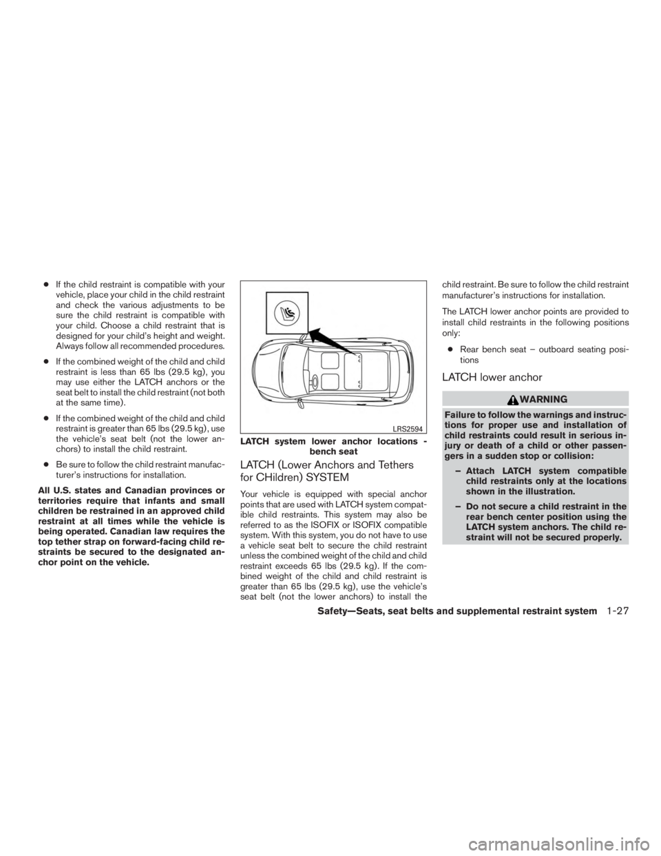
The LATCH lower anchor points are provided to
install child restraints in the following positions
only:
● Rear bench seat – outboard seating posi-
tions
LATCH lower anchor
Page 71 of 424
WARNING
●The front air bags ordinarily will not
inflate in the event of a side impact, rear
impact, rollover, or lower severity fron-
tal collision. Always wear your seat
belts to help reduce the risk or severity
of injury in various kinds of accidents.
● The front passenger air bag will not
inflate if the passenger air bag status
light is lit or if the front passenger seat
is unoccupied. For additional informa-
tion, refer to “Front passenger air bag
and status light” in this section. ●
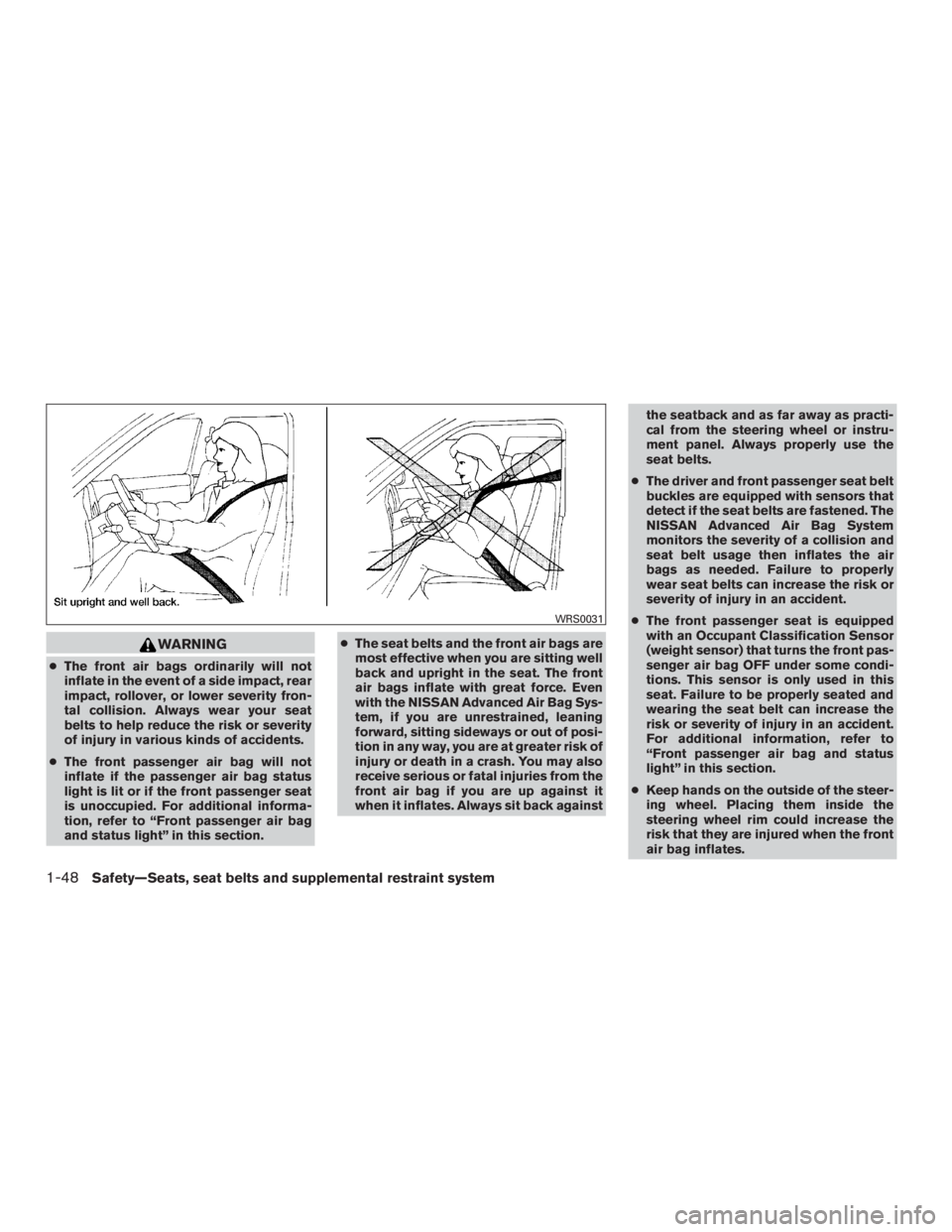
The seat belts and the front air bags are
most effective when you are sitting well
back and upright in the seat. The front
air bags inflate with great force. Even
with the NISSAN Advanced Air Bag Sys-
tem, if you are unrestrained, leaning
forward, sitting sideways or out of posi-
tion in any way, you are at greater risk of
injury or death in a crash. You may also
receive serious or fatal injuries from the
front air bag if you are up against it
when it inflates. Always sit back against the seatback and as far away as practi-
cal from the steering wheel or instru-
ment panel. Always properly use the
seat belts.
● The driver and front passenger seat belt
buckles are equipped with sensors that
detect if the seat belts are fastened. The
NISSAN Advanced Air Bag System
monitors the severity of a collision and
seat belt usage then inflates the air
bags as needed. Failure to properly
wear seat belts can increase the risk or
severity of injury in an accident.
● The front passenger seat is equipped
with an Occupant Classification Sensor
(weight sensor) that turns the front pas-
senger air bag OFF under some condi-
tions. This sensor is only used in this
seat. Failure to be properly seated and
wearing the seat belt can increase the
risk or severity of injury in an accident.
For additional information, refer to
“Front passenger air bag and status
light” in this section.
● Keep hands on the outside of the steer-
ing wheel. Placing them inside the
steering wheel rim could increase the
risk that they are injured when the front
air bag inflates.
Page 79 of 424
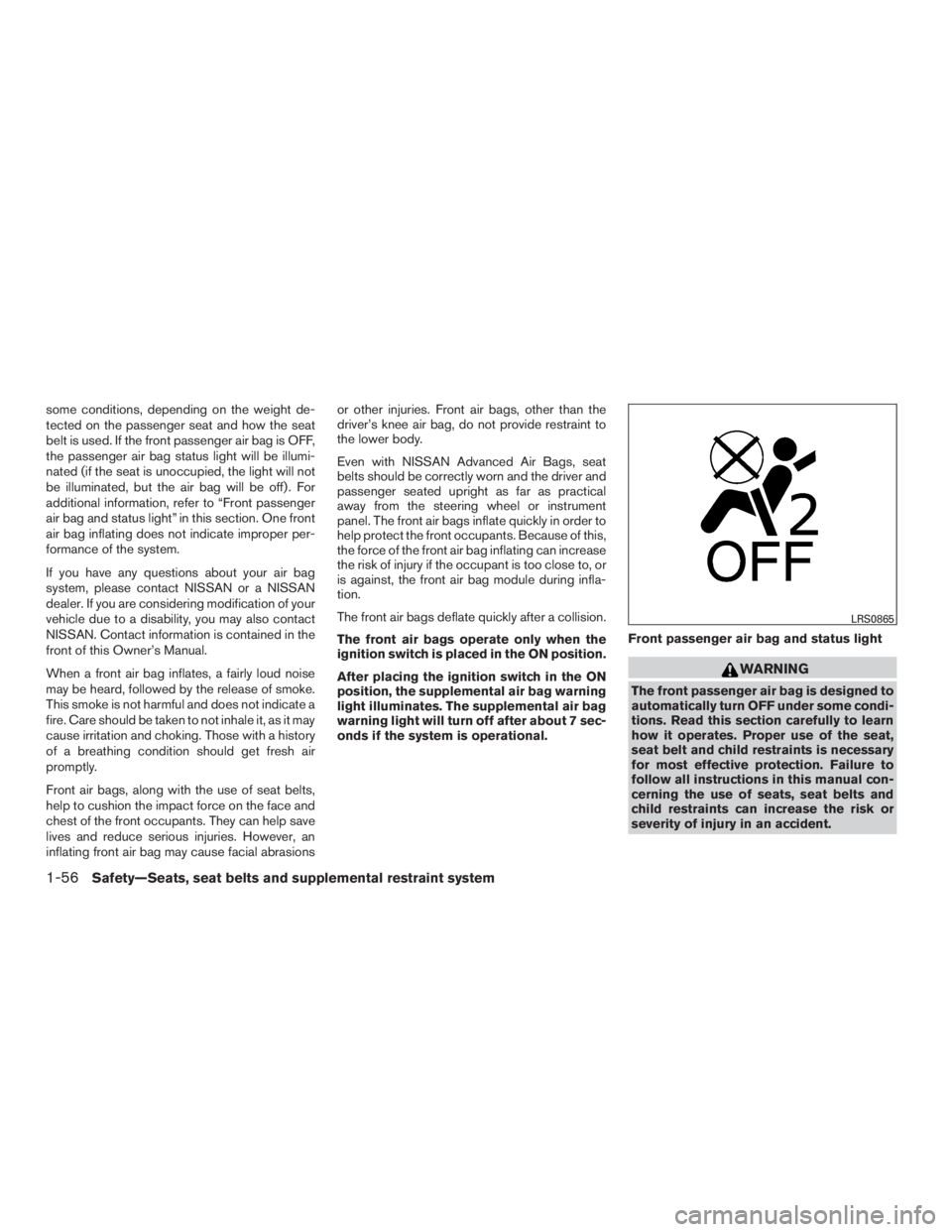
some conditions, depending on the weight de-
tected on the passenger seat and how the seat
belt is used. If the front passenger air bag is OFF,
the passenger air bag status light will be illumi-
nated (if the seat is unoccupied, the light will not
be illuminated, but the air bag will be off) . For
additional information, refer to “Front passenger
air bag and status light” in this section. One front
air bag inflating does not indicate improper per-
formance of the system.
If you have any questions about your air bag
system, please contact NISSAN or a NISSAN
dealer. If you are considering modification of your
vehicle due to a disability, you may also contact
NISSAN. Contact information is contained in the
front of this Owner’s Manual.
When a front air bag inflates, a fairly loud noise
may be heard, followed by the release of smoke.
This smoke is not harmful and does not indicate a
fire. Care should be taken to not inhale it, as it may
cause irritation and choking. Those with a history
of a breathing condition should get fresh air
promptly.
Front air bags, along with the use of seat belts,
help to cushion the impact force on the face and
chest of the front occupants. They can help save
lives and reduce serious injuries. However, an
inflating front air bag may cause facial abrasionsor other injuries. Front air bags, other than the
driver’s knee air bag, do not provide restraint to
the lower body.
Even with NISSAN Advanced Air Bags, seat
belts should be correctly worn and the driver and
passenger seated upright as far as practical
away from the steering wheel or instrument
panel. The front air bags inflate quickly in order to
help protect the front occupants. Because of this,
the force of the front air bag inflating can increase
the risk of injury if the occupant is too close to, or
is against, the front air bag module during infla-
tion.
The front air bags deflate quickly after a collision.
The front air bags operate only when the
ignition switch is placed in the ON position.
After placing the ignition switch in the ON
position, the supplemental air bag warning
light illuminates. The supplemental air bag
warning light will turn off after about 7 sec-
onds if the system is operational.
Front passenger air bag and status light
Page 136 of 424
Do not apply any load directly to the roof side
rails. Cross bars must be installed before apply-
ing load/cargo/luggage to the roof of the vehicle.
Be careful that your vehicle does not exceed the
Gross Vehicle Weight Rating (GVWR) or its
Gross Axle Weight Rating (GAWR front and
rear) . The GVWR and GAWR are located on the
F.M.V.S.S. or C.V.M.S.S. certification label (lo-
cated on the driver’s door pillar) . For additional
information regarding GVWR and GAWR, refer
to “Vehicle loading information” in the “Technical
and customer information” section of this manual.
Page 398 of 424
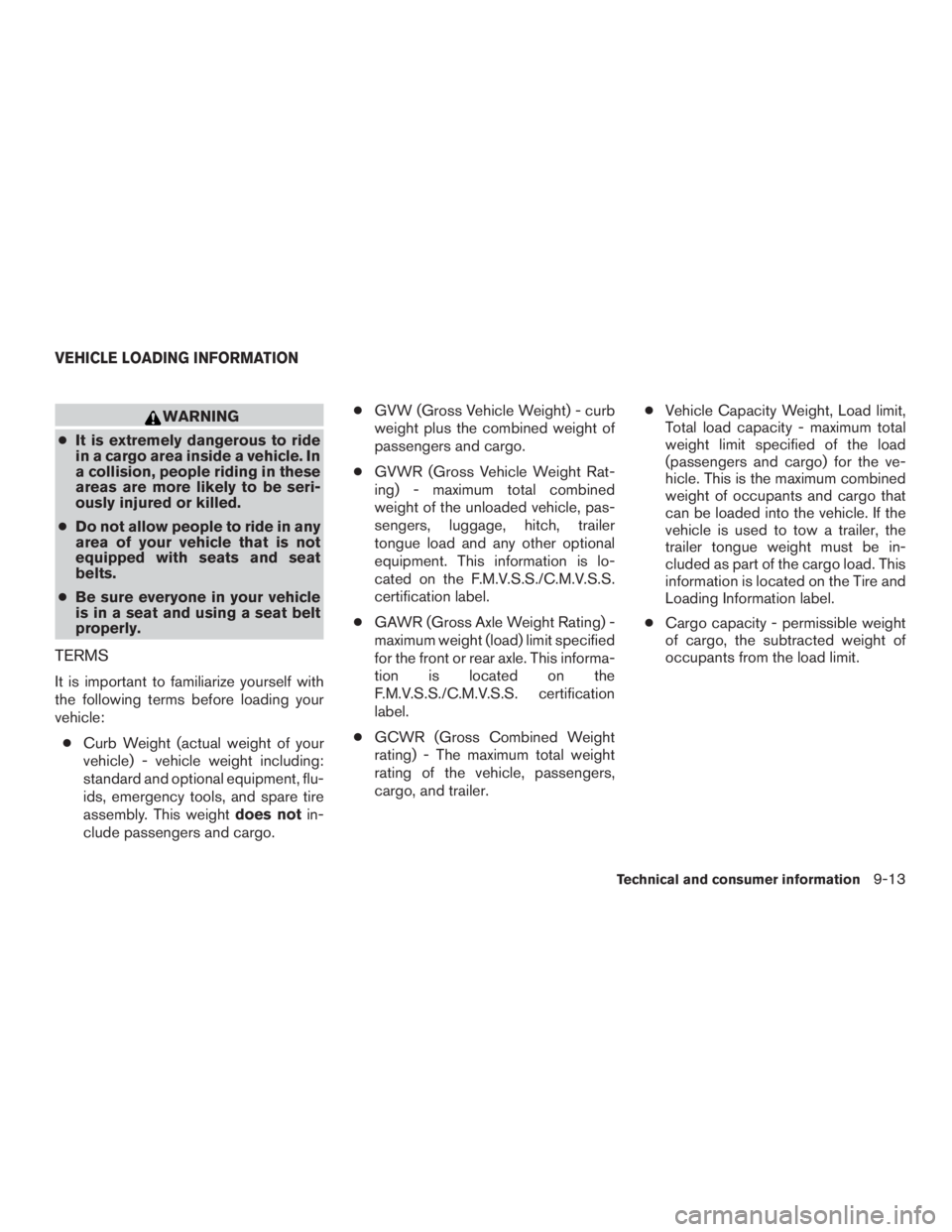
WARNING
● It is extremely dangerous to ride
in a cargo area inside a vehicle. In
a collision, people riding in these
areas are more likely to be seri-
ously injured or killed.
● Do not allow people to ride in any
area of your vehicle that is not
equipped with seats and seat
belts.
● Be sure everyone in your vehicle
is in a seat and using a seat belt
properly.
TERMS
It is important to familiarize yourself with
the following terms before loading your
vehicle:
● Curb Weight (actual weight of your
vehicle) - vehicle weight including:
standard and optional equipment, flu-
ids, emergency tools, and spare tire
assembly. This weight does notin-
clude passengers and cargo. ●
GVW (Gross Vehicle Weight) - curb
weight plus the combined weight of
passengers and cargo.
● GVWR (Gross Vehicle Weight Rat-
ing) - maximum total combined
weight of the unloaded vehicle, pas-
sengers, luggage, hitch, trailer
tongue load and any other optional
equipment. This information is lo-
cated on the F.M.V.S.S./C.M.V.S.S.
certification label.
● GAWR (Gross Axle Weight Rating) -
maximum weight (load) limit specified
for the front or rear axle. This informa-
tion is located on the
F.M.V.S.S./C.M.V.S.S. certification
label.
● GCWR (Gross Combined Weight
rating) - The maximum total weight
rating of the vehicle, passengers,
cargo, and trailer. ●
Vehicle Capacity Weight, Load limit,
Total load capacity - maximum total
weight limit specified of the load
(passengers and cargo) for the ve-
hicle. This is the maximum combined
weight of occupants and cargo that
can be loaded into the vehicle. If the
vehicle is used to tow a trailer, the
trailer tongue weight must be in-
cluded as part of the cargo load. This
information is located on the Tire and
Loading Information label.
● Cargo capacity - permissible weight
of cargo, the subtracted weight of
occupants from the load limit.
VEHICLE LOADING INFORMATION
Technical and consumer information9-13
Page 405 of 424
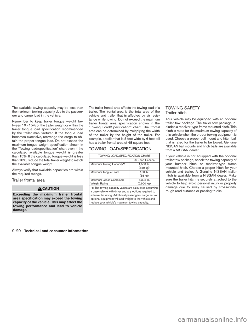
The available towing capacity may be less than
the maximum towing capacity due to the passen-
ger and cargo load in the vehicle.
Remember to keep trailer tongue weight be-
tween 10 - 15% of the trailer weight or within the
trailer tongue load specification recommended
by the trailer manufacturer. If the tongue load
becomes excessive, rearrange the cargo to ob-
tain the proper tongue load. Do not exceed the
maximum tongue weight specification shown in
the “Towing load/specification” chart even if the
calculated available tongue weight is greater
than 15%. If the calculated tongue weight is less
than 10%, reduce the total trailer weight to match
the available tongue weight.
Always verify that available capacities are within
the required ratings.
Trailer frontal area
Page 406 of 424
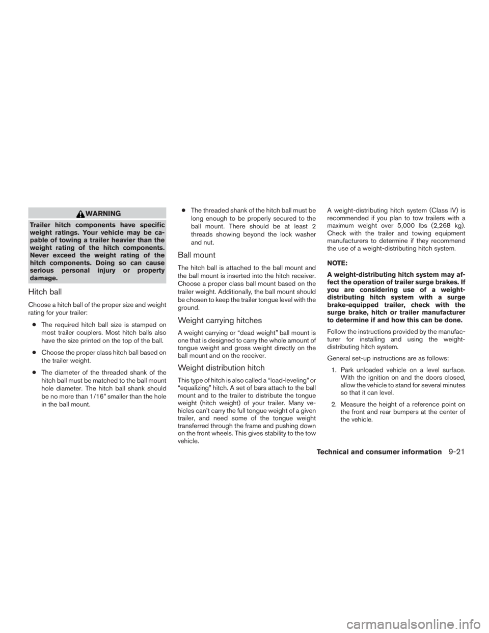
WARNING
Trailer hitch components have specific
weight ratings. Your vehicle may be ca-
pable of towing a trailer heavier than the
weight rating of the hitch components.
Never exceed the weight rating of the
hitch components. Doing so can cause
serious personal injury or property
damage.
Hitch ball
Choose a hitch ball of the proper size and weight
rating for your trailer:● The required hitch ball size is stamped on
most trailer couplers. Most hitch balls also
have the size printed on the top of the ball.
● Choose the proper class hitch ball based on
the trailer weight.
● The diameter of the threaded shank of the
hitch ball must be matched to the ball mount
hole diameter. The hitch ball shank should
be no more than 1/16” smaller than the hole
in the ball mount. ●
The threaded shank of the hitch ball must be
long enough to be properly secured to the
ball mount. There should be at least 2
threads showing beyond the lock washer
and nut.
Ball mount
The hitch ball is attached to the ball mount and
the ball mount is inserted into the hitch receiver.
Choose a proper class ball mount based on the
trailer weight. Additionally, the ball mount should
be chosen to keep the trailer tongue level with the
ground.
Weight carrying hitches
A weight carrying or “dead weight” ball mount is
one that is designed to carry the whole amount of
tongue weight and gross weight directly on the
ball mount and on the receiver.
Weight distribution hitch
This type of hitch is also called a “load-leveling” or
“equalizing” hitch. A set of bars attach to the ball
mount and to the trailer to distribute the tongue
weight (hitch weight) of your trailer. Many ve-
hicles can’t carry the full tongue weight of a given
trailer, and need some of the tongue weight
transferred through the frame and pushing down
on the front wheels. This gives stability to the tow
vehicle. A weight-distributing hitch system (Class IV) is
recommended if you plan to tow trailers with a
maximum weight over 5,000 lbs (2,268 kg).
Check with the trailer and towing equipment
manufacturers to determine if they recommend
the use of a weight-distributing hitch system.
NOTE:
A weight-distributing hitch system may af-
fect the operation of trailer surge brakes. If
you are considering use of a weight-
distributing hitch system with a surge
brake-equipped trailer, check with the
surge brake, hitch or trailer manufacturer
to determine if and how this can be done.
Follow the instructions provided by the manufac-
turer for installing and using the weight-
distributing hitch system.
General set-up instructions are as follows:
1. Park unloaded vehicle on a level surface. With the ignition on and the doors closed,
allow the vehicle to stand for several minutes
so that it can level.
2. Measure the height of a reference point on the front and rear bumpers at the center of
the vehicle.
Technical and consumer information9-21
Page 417 of 424
Child restraints.......1-23,1-24,1-25,1-27
LATCH (Lower Anchors and Tethers for
CHildren) System ..............1-27
Precautions on child
restraints.........1-25,1-32,1-39,1-43
Top tether strap anchor point locations . .1-30
Child restraint with top tether strap .......1-29
Child safety rear door lock ............3-7
Chimes, audible reminders ...........2-14
Cleaningexteriorandinterior........7-2,7-4
Clock setting
(models without Navigation System) ......4-39
C.M.V.S.S. certification label ..........9-11
Cold weather driving ...............5-73
Compact disc (CD) player ...........4-41
Connect phone .................4-50
Consolebox...................2-43
Continuously Variable Transmission (CVT) . . .5-15 Continuously Variable Transmission (CVT)
fluid ......................8-13
Driving with Continuously Variable
Transmission (CVT) .............5-15
Controls Heater and air conditioner controls .....4-27
Coolant Capacities and recommended
fuel/lubricants .................9-2
Changing engine coolant ...........8-8
Checking engine coolant level ........8-8
Engine coolant temperature gauge .....2-5
Corrosionprotection ...............7-5
Cruisecontrol..................5-33
Cupholders...................2-41 D
Daytime running light system (Canada only) . .2-32
Defroster switch Rear window and outside mirror defroster
switch.....................2-30
Dimensionsandweights.............9-9
Dimmer switch for instrument panel ......2-33
Door locks .....................3-4
Drive belt .....................8-17
Drive positioner, Automatic ....3-35,3-36,3-37
Driving Cold weather driving .............5-73
Driving with Continuously Variable
Transmission (CVT) .............5-15
Precautions when starting and
driving ...................5-2,5-8
Driving the vehicle ................5-15
E
Economy - fuel ..................5-64
Emission control information label .......9-11
Emission control system warranty .......9-27
Engine Before starting the engine ..........5-14
Block heater .................5-74
Capacities and recommended
fuel/lubricants .................9-2
Changingenginecoolant...........8-8
Changingengineoil.............8-10
Changing engine oil filter ..........8-12
Checking engine coolant level ........8-8
Checking engine oil level ...........8-9 Engine compartment check locations
....8-6
Engine coolant temperature gauge .....2-5
Engine cooling system ............8-7
Engineoil ...................8-9
Engine oil and oil filter recommendation . . .9-6
Engine oil pressure warning light ....2-8,2-9
Engine oil viscosity ..............9-6
Engine serial number ............9-11
Engine specifications .............9-8
Starting the engine .............5-14
Engine coolant temperature gauge .......2-5
Event
data recorders ..............9-29
Exhaust gas (Carbon monoxide) .........5-2
Explanation of maintenance items ........8-2
Extended storage switch ............8-24
Eyeglass case ..................2-41
F
Flashers (See hazard warning flasher switch) . .6-2
Flat tire .......................6-3
Floor mat positioning aid .............7-5
Fluid Brake fluid ..................8-14
Capacities and recommended
fuel/lubricants.................9-2
Continuously Variable Transmission (CVT)
fluid......................8-13
Enginecoolant.................8-7
Engineoil ...................8-9
Power steering fluid .............8-13
Windshield-washer fluid ...........8-14
F.M.V.S.S. certification label ...........9-11
Foglightswitch .................2-34
10-2