2015 NISSAN MICRA mirror
[x] Cancel search: mirrorPage 125 of 293

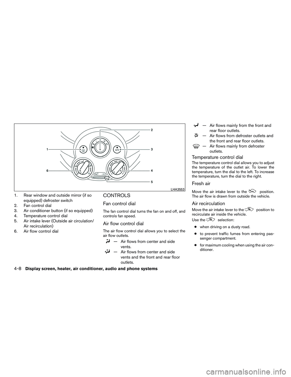
1. Rear window and outside mirror (if soequipped) defroster switch
2. Fan control dial
3. Air conditioner button (if so equipped)
4. Temperature control dial
5. Air intake lever (Outside air circulation/
Air recirculation)
6. Air flow control dialCONTROLS
Fan control dial
The fan control dial turns the fan on and off, and
controls fan speed.
Air flow control dial
The air flow control dial allows you to select the
air flow outlets.
— Air flows from center and side
vents.
— Air flows from center and sidevents and the front and rear floor
outlets.
— Air flows mainly from the front and rear floor outlets.
— Air flows from defroster outlets andthe front and rear floor outlets.
— Air flows mainly from defrosteroutlets.
Temperature control dial
The temperature control dial allows you to adjust
the temperature of the outlet air. To lower the
temperature, turn the dial to the left. To increase
the temperature, turn the dial to the right.
Fresh air
Move the air intake lever to theposition.
The air flow is drawn from outside the vehicle.
Air recirculation
Move the air intake lever to theposition to
recirculate air inside the vehicle.
Use the
selection:
● when driving on a dusty road.
● to prevent traffic fumes from entering pas-
senger compartment.
● for maximum cooling when using the air con-
ditioner.
LHA3553
4-8Display screen, heater, air conditioner, audio and phone systems
Page 126 of 293

Air conditioner button (if soequipped)
Start the engine, turn the fan control dial to the
desired position and press the
button to
turn on the air conditioner. The indicator light
comes on when the air conditioner is operating.
To turn off the air conditioner, press the
button again.
Rear window and outside mirror (if so
equipped) defroster button
For additional information, refer to “Rear window
and outside mirror (if so equipped) defroster
switch” in the “Instruments and controls” section
of this manual.
HEATER OPERATION
Heating
This mode is used to direct heated air to the foot
outlets. Some air also flows from the defrost
outlets.
1. Move the air intake lever to the
posi-
tion for normal heating.
2. Turn the air flow control dial to the
position.
3. Turn the fan control dial to the desired posi- tion. 4. Turn the temperature control dial to the de-
sired position between the middle and the
hot position.
Ventilation
This mode directs outside air to the side and
center vents.
1. Move the air intake lever to the
posi-
tion.
2. Turn the air flow control dial to the
position.
3. Turn the fan control dial to the desired posi- tion.
4. Turn the temperature control dial to the de- sired position.
Defrosting or defogging
This mode directs the air to the defrost outlets to
defrost/defog the windows.
1. Move the air intake lever to the
posi-
tion.
2. Turn the air flow control dial to the
position.
3. Turn the fan control dial to the desired posi- tion. 4. Turn the temperature control dial to the de-
sired position between the middle and the
hot position.
5. Align left and right vents to direct air flow toward the front side windows.
● To quickly remove ice or fog from the win-
dows, turn the fan control dial to the maxi-
mum position and the temperature control
dial to the full hot position.
When the
orposition is selected,
press the
button to turn on the air condi-
tioner for better performance. This will dehumidify
the air and help defog the windows.
Bi-level heating
This mode directs cooler air from the side and
center vents and warmer air from the floor outlets.
When the temperature control dial is moved to
the full hot or full cool position, the air between
the vents and the floor outlets is the same tem-
perature.
1. Move the air intake lever to the
posi-
tion.
2. Turn the air flow control dial to the
position.
Display screen, heater, air conditioner, audio and phone systems4-9
Page 133 of 293

CONTROLS
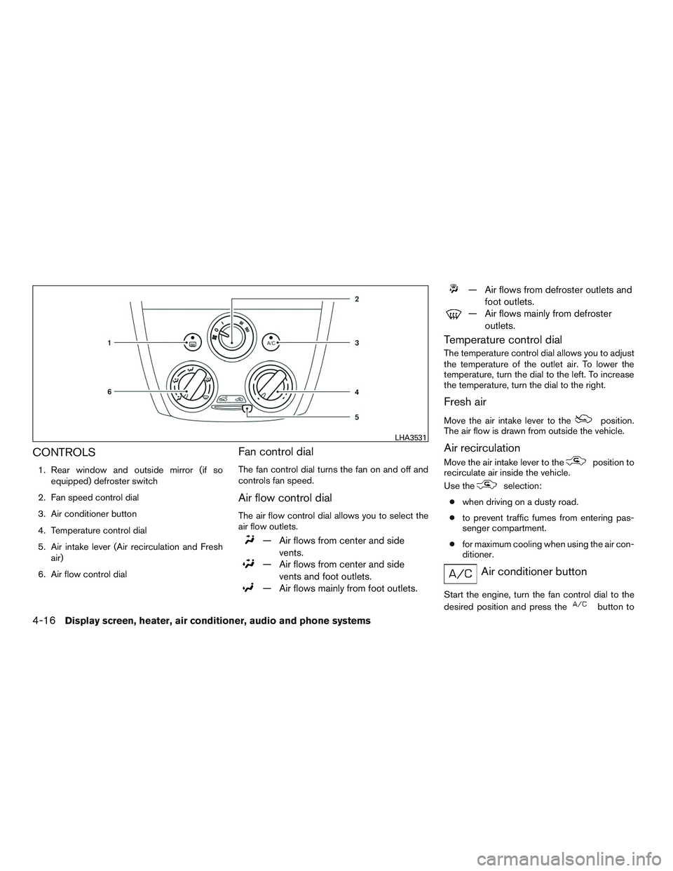
1. Rear window and outside mirror (if soequipped) defroster switch
2. Fan speed control dial
3. Air conditioner button
4. Temperature control dial
5. Air intake lever (Air recirculation and Fresh air)
6. Air flow control dial
Fan control dial
The fan control dial turns the fan on and off and
controls fan speed.
Air flow control dial
The air flow control dial allows you to select the
air flow outlets.
— Air flows from center and side vents.
— Air flows from center and sidevents and foot outlets.
— Air flows mainly from foot outlets.
— Air flows from defroster outlets and foot outlets.
— Air flows mainly from defrosteroutlets.
Temperature control dial
The temperature control dial allows you to adjust
the temperature of the outlet air. To lower the
temperature, turn the dial to the left. To increase
the temperature, turn the dial to the right.
Fresh air
Move the air intake lever to theposition.
The air flow is drawn from outside the vehicle.
Air recirculation
Move the air intake lever to theposition to
recirculate air inside the vehicle.
Use the
selection:
● when driving on a dusty road.
● to prevent traffic fumes from entering pas-
senger compartment.
● for maximum cooling when using the air con-
ditioner.
Air conditioner button
Start the engine, turn the fan control dial to the
desired position and press the
button to
LHA3531
4-16Display screen, heater, air conditioner, audio and phone systems
Page 134 of 293

turn on the air conditioner. The indicator light
comes on when the air conditioner is operating.
To turn off the air conditioner, press the
button again.
The air conditioner cooling function oper-
ates only when the engine is running.
Rear window and outside mirror (if so
equipped) defroster button
For additional information, refer to “Rear window
and outside mirror (if so equipped) defroster
switch” in the “Instruments and controls” section
of this manual.
HEATER OPERATION
Heating
This mode is used to direct heated air to the foot
outlets. Some air also flows from the defrost
outlets.1. Move the air intake lever to the
posi-
tion for normal heating.
2. Turn the air flow control dial to the
position.
3. Turn the fan control dial to the desired posi- tion. 4. Turn the temperature control dial to the de-
sired position between the middle and the
hot position.
Ventilation
This mode directs outside air to the side and
center vents.
1. Move the air intake lever to the
posi-
tion.
2. Turn the air flow control dial to the
position.
3. Turn the fan control dial to the desired posi- tion.
4. Turn the temperature control dial to the de- sired position.
Defrosting or defogging
This mode directs the air to the defrost outlets to
defrost/defog the windows.
1. Move the air intake lever to the
posi-
tion.
2. Turn the air flow control dial to the
position.
3. Turn the fan control dial to the desired posi- tion. 4. Turn the temperature control dial to the de-
sired position between the middle and the
hot position.
● To quickly remove ice or fog from the win-
dows, turn the fan control dial to the maxi-
mum position and the temperature control
dial to the full hot position.
When the
orposition is selected,
press the
button to turn on the air condi-
tioner for better performance. This will dehumidify
the air and help defog the windows.
Bi-level heating
This mode directs cooler air from the side and
center vents and warmer air from the floor outlets.
When the temperature control dial is moved to
the full hot or full cool position, the air between
the vents and the floor outlets is the same tem-
perature.
1. Move the air intake lever to
position.
2. Turn the air flow control dial to the
position.
3. Turn the fan control dial to the desired posi- tion.
4. Turn the temperature control dial to the de- sired position.
Display screen, heater, air conditioner, audio and phone systems4-17
Page 180 of 293

NISSAN VEHICLE IMMOBILIZER
SYSTEM
The NISSAN Vehicle Immobilizer system will not
allow the engine to start without the use of the
registered key.
If the engine fails to start using a registered key
(for example, when interference is caused by
another registered key, an automated toll road
device or automatic payment device on the key
ring) , restart the engine using the following pro-
cedure:1. Leave the ignition switch in the ON position for approximately 5 seconds.
2. Place the ignition switch in the OFF or LOCK position, and wait approximately
10 seconds.
3. Repeat Steps 1 and 2.
4. Restart the engine while holding the device (which may have caused the interference)
separate from the registered key.
If the no start condition re-occurs, NISSAN rec-
ommends placing the registered key on a sepa-
rate key ring to avoid interference from other
devices. ●
Make sure the area around the vehicle is
clear.
● Check fluid levels such as engine oil, cool-
ant, brake and clutch fluid (if so equipped) ,
and windshield-washer fluid as frequently as
possible, or at least whenever you refuel.
● Check that all windows and lights are clean.
● Visually inspect tires for their appearance
and condition. Also check tires for proper
inflation.
● Lock all doors.
● Position seat and adjust head restraints.
● Adjust inside and outside mirrors.
● Fasten seat belts and ask all passengers to
do likewise.
● Check the operation of warning lights when
the key is turned to the ON position. For
additional information, refer to
“Warning/indicator lights and audible re-
minders” in the “Instruments and controls”
section of this manual. 1. Apply the parking brake.
2.
Automatic transmission:
Move the shift lever to P (Park) or N (Neu-
tral) . P (Park) is recommended.
The shift lever cannot be moved out of
the P (Park) position and into any of
the other gear positions if the ignition
switch is placed in the OFF position or
if the key is removed from the ignition
switch.
The starter is designed not to operate if
the shift lever is in any of the driving
positions.
Manual transmission:
Move the shift lever to N (Neutral) . Depress
the clutch pedal to the floor while cranking
the engine.
3. Crank the engine with your foot off the
accelerator pedal by placing the ignition
switch in the START position. Release the
key when the engine starts. If the engine
starts, but fails to run, repeat the above
procedure.
● If the engine is very hard to start in ex-
tremely cold weather or when restarting,
depress the accelerator pedal a little (ap-
proximately 1/3 to the floor) and hold it
BEFORE STARTING THE ENGINE STARTING THE ENGINE
Starting and driving5-7
Page 288 of 293

Fuel-filler lid and cap............3-11
Fuel gauge ...................2-5
Fuel octane rating ...............9-5
Fuel gauge .....................2-5
Fuses.......................8-20
Fusible links ...................8-21
G
Gascap .....................3-11
Gauge Fuel gauge ...................2-5
Odometer ...................2-4
Speedometer .................2-3
Tachometer ..................2-4
Trip computer .................2-5
Trip odometer .................2-4
General maintenance ...............8-2
Glovebox.....................2-23
H
Hands-free phone system, Bluetooth® ....4-46
Hazard warning flasher switch ..........6-2
Headlight and turn signal switch ........2-17
Headlightcontrolswitch ............2-17
Headlights....................8-25
Head restraints ..................1-6
Heater Heater and air conditioner controls . .4-7, 4-15
Heater operation ............4-9,4-17
Hood release ...................3-9
Horn .......................2-20 I
Ignition switch ...................5-5
Immobilizer system ..........2-13,3-2,5-7
Important vehicle information label .......9-11
Increasing fuel economy .............5-17
Indicator lights and audible reminders
(See warning/indicator lights and audible
reminders) .....................2-7
Inside mirror ...................3-14
Instrument brightness control ..........2-18
Instrument panel ...............0-6,2-2
Instrument panel dimmer switch ........2-18
Intelligent Key system Remote keyless entry operation .......3-7
Interiorlight....................2-27
iPod® Player ...................4-42
ISOFIX child restraints .............1-20
J
Jump starting ...............6-10,8-15
K
Key.........................3-2
Key fob battery replacement ..........8-24
Keyless entry With Intelligent Key system
(See Intelligent Key system) .........3-7
Keyless entry system
(See remote keyless entry system) ........3-6 L
Labels Air conditioner specification label .....9-12
C.M.V.S.S. certification label ........9-11
Emission control information label .....9-11
Engine serial number ............9-11
Tire and Loading Information label .....9-12
Vehicle identification number (VIN) plate . .9-10
Warning labels (for SRS) ..........1-54
LATCH (Lower Anchors and Tethers for CHildren)
System ......................1-20
License plate Installing the license plate ..........9-12
Light A
irbagwarninglight.........1-55,2-10
Brake light (See stop light) .........8-29
Bulb check/instrument panel .........2-7
Bulb replacement ..............8-29
Charge warning light .............2-8
Foglights...................8-29
Headlightandturnsignalswitch......2-17
Headlight control switch ..........2-17
Headlights..................8-25
Interior light ..................2-27
Lightbulbs..................8-25
Low windshield-washer fluid warning
light.......................2-9
Passenger air bag and status light .....1-49
Security indicator light ............2-11
Warning/indicator lights and audible
reminders ...................2-7
Lock Child safety rear door lock ..........3-5
Doorlocks...................3-3
10-3
Page 289 of 293

Fuel-filler door lock opener lever......3-11
Power door locks ...............3-4
Lowfuelwarninglight...............2-9
Low windshield-washer fluid warning light . . .2-9
Luggage (See vehicle loading information) . .9-13
M
Maintenance Generalmaintenance.............8-2
Insidethevehicle...............8-3
Maintenanceprecautions...........8-5
Outsidethevehicle..............8-2
Seat belt maintenance ............1-16
Under the hood and vehicle .........8-4
Maintenance requirements ............8-2
Malfunctionindicatorlight............2-11
Manual front seat adjustment ...........1-2
Manual windows .................2-26
Map pocket ....................2-21
Meters and gauges ................2-3
Instrument brightness control ........2-18
Mirror Inside mirror .................3-14
Outside mirror control ............3-15
Outside mirrors ...............3-15
Vanity mirror .................3-14
Mirrors ......................3-14
Multi-remote control system
(See remote keyless entry system) ........3-6 N
NISSAN vehicle immobilizer
system .................2-13,3-2,5-7
O
Octane rating (See fuel octane rating) ......9-5
Odometer .....................2-4
Oil Capacities and recommended
fuel/lubricants .................9-2
Changingengineoil.............8-10
Changing engine oil filter ..........8-11
Checking engine oil level ...........8-9
Engineoil ...................8-9
Engine oil and oil filter recommendation . . .9-6
Engine oil viscosity ..............9-6
Oneshotcall...................4-49
Outside mirror control ..............3-15
Outside mirrors .................3-15
Overdrive switch .................5-12
Overheat If your vehicle overheats ...........6-12
Owner’s manual order form ...........9-20
Owner’s manual/service manual order
information ....................9-20
P
Parking Parking brake operation ...........5-14
Parking/parking on hills ...........5-18
Phone, Bluetooth® hands-free system .....4-46Power
Power door locks ...............3-4
Poweroutlet.................2-21
Power rear windows .............2-26
Power steering system ...........5-19
Power windows ...............2-24
Rear power windows ............2-26
Poweroutlet...................2-21
Power steering ..................5-19
Precautions Maintenance precautions ...........8-5
Precautions on booster
seats...........1-18,1-25,1-31,1-36
Precautions on child
restraints .........1-18,1-25,1-31,1-36
Precautionsonseatbeltusage.......1-10
Precautions on supplemental restraint
system ....................1-40
Precautions when starting and driving ....5-2
Push starting ...................6-12
R
Radio CarphoneorCBradio ...........4-45
FM-AM
radio with compact disc (CD)
player.....................4-31
FM/AM/SAT radio with compact disc (CD)
player.....................4-35
Steering wheel audio control switch ....4-44
Readiness for inspection maintenance (I/M)
test........................9-19
Rear power windows ..............2-26
Rearseat......................1-4
RearView Monitor ..............4-2,4-3
10-4
Page 291 of 293

Theft (NISSAN vehicle immobilizer system) ,
engine start..............2-13,3-2,5-7
Three-way catalyst ................5-2
Tilting steering wheel ..............3-13
Tire Flat tire .....................6-2
Spare tire ................6-3,8-42
Tire and Loading Information label .....9-12
Tire chains ..................8-40
Tirepressure.................8-34
Tirerotation..................8-40
Types of tires .................8-39
Uniform tire quality grading .........9-17
Wheels and tires ...............8-34
Wheel/tire size .................9-9
Towing Flattowing..................9-16
Towtrucktowing...............6-13
Trailertowing.................9-16
Towing a trailer ..................9-16
Transmission Automatic transmission fluid (ATF) .....8-11
Driving with automatic transmission .....5-8
Driving with manual transmission ......5-12
Shiftselectorlockrelease..........5-11
Travel (See registering your vehicle in another
country) ......................9-10
Trip computer ...................2-5
Trip odometer ...................2-4
Turnsignalswitch................2-19
U
Uniform tire quality grading ...........9-17
USB interface ..................4-40 Audio file operation
.............4-41
V
Vanity mirror ...................3-14
Vehicle dimensions and weights .........9-9
Vehicle dynamic control (VDC) off switch . . .2-20
Vehicle dynamic control (VDC) system .....5-21
Vehicle Dynamic Control (VDC) system ....5-21
Vehicle identification ...............9-10
Vehicle identification number (VIN)
(Chassis number) ................9-10
Vehicle identification number (VIN) plate ....9-10
Vehicle immobilizer system ......2-13,3-2,5-7
Vehicle loading information ...........9-13
Vehicle recovery .................6-15
Vehicle security system .............2-13
Vehicle security system (NISSAN vehicle immobi-
lizer system) , engine start ......2-13,3-2,5-7
Ventilators .....................4-6
Visors.......................3-13
Voice Prompt Interrupt ..............4-49
W
Warning Air bag warning light .........1-55,2-10
Anti-lock brake warning light .........2-8
Battery charge warning light .........2-8
Brake warning light ..............2-8
Door open warning light ...........2-8
Engine oil pressure warning light .......2-8
Hazard warning flasher switch ........6-2
Low fuel warning light .............2-9Low windshield-washer fluid warning light..2-9
Passenger air bag and status light .....1-49
Seat belt warning light ............2-9
Supplemental air bag warning light. .1-55, 2-10
Vehicle security system ...........2-13
Warning/indicator lights and audible
reminders ...................2-7
Warning labels (for SRS) ..........1-54
Warning/indicator lights and audible
reminders .....................2-7
Audible reminders ...............2-7
Indicatorlights.................2-7
Warninglights.................2-7
Warninglights...................2-7
Washer switch Rear window wiper and washer
switches ...................2-16
Windshield wiper and washer switch . . .2-14
Weights(Seedimensionsandweights).....9-9
Wheels and tires .................8-34
Wheel/tire size ...................9-9
When traveling or registering your vehicle in
anothercountry .................9-10
Windows Locking passengers’ windows .......2-26
Manual windows ...............2-26
Power rear windows .............2-26
Power windows ...............2-24
Rear power windows ............2-26
Windshield-washer fluid .............8-13
Windshield wiper and washer switch .....2-14
Windshield wiper blades ............8-17
Wiper
Rear window wiper and washer switches. .2-16
Windshield wiper and washer switch . . .2-14
Wiperblades.................8-17
10-6