Page 157 of 466
Always evenly distribute the cargo on the tubular
roof rack.The maximum total load is 125 lb
(56 kg) evenly distributed. Be careful that your
vehicle does not exceed the Gross Vehicle
Weight Rating (GVWR) or the Gross Axle
Weight Ratings (GAWR front and rear) . The
GVWR and GAWR are located on the F.M.V.S.S.
label (located on the driver’s side door jamb
pillar) . For additional information regarding
GVWR and GAWR, refer to “Vehicle loading
information” in the “Technical and consumer in-
formation” section of this manual.
The front crossbar can be adjusted or removed.
Use the TORX® driver provided in the tool kit to
loosen both crossbar adjusting screws.
To adjust:
1. Loosen the adjusting screws with the TORX® driver
�1by turning counterclock-
wise
�A.
2. When the clamp is loosened, move the crossbar so the cargo can be positioned on
the crossbar
�B.
3. Tighten the crossbar adjusting screws with the TORX® driver by turning clockwise.
4. Secure the cargo with rope.
5. Always check the tightness of the crossbar adjusting screws. To remove:
1. Loosen the adjusting screws with the TORX® driver
�1by turning counterclock-
wise
�A.
2. Rotate the clamps
�C.
3. Remove the crossbar.
4. Reverse to install.
5. Always check the tightness of the crossbar adjusting screws.
If you hear wind noise coming from the roof rack
while driving, adjust the roof rack crossbar to the
neutral position.
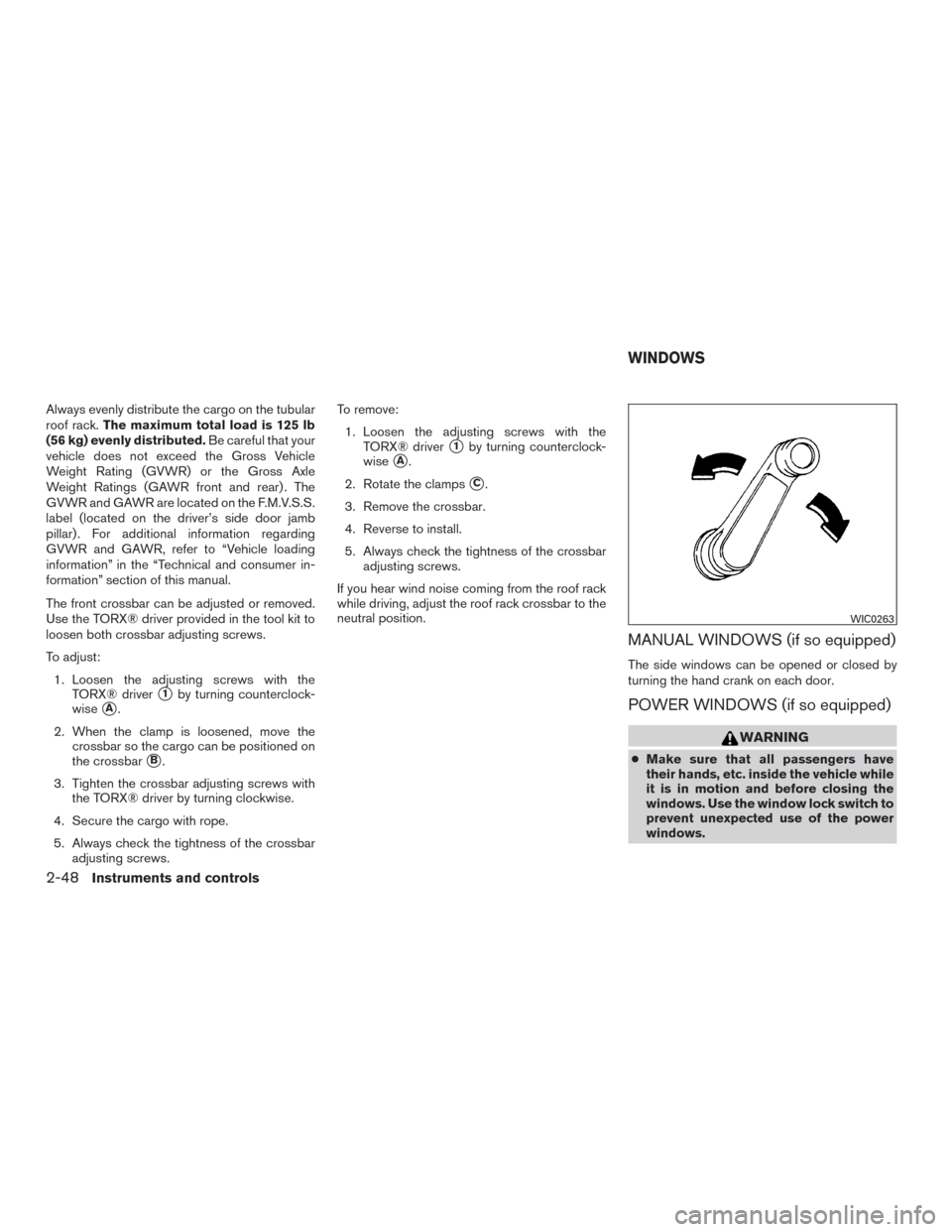
MANUAL WINDOWS (if so equipped)
The side windows can be opened or closed by
turning the hand crank on each door.
POWER WINDOWS (if so equipped)
WARNING
● Make sure that all passengers have
their hands, etc. inside the vehicle while
it is in motion and before closing the
windows. Use the window lock switch to
prevent unexpected use of the power
windows.
WIC0263
WINDOWS
2-48Instruments and controls
Page 163 of 466
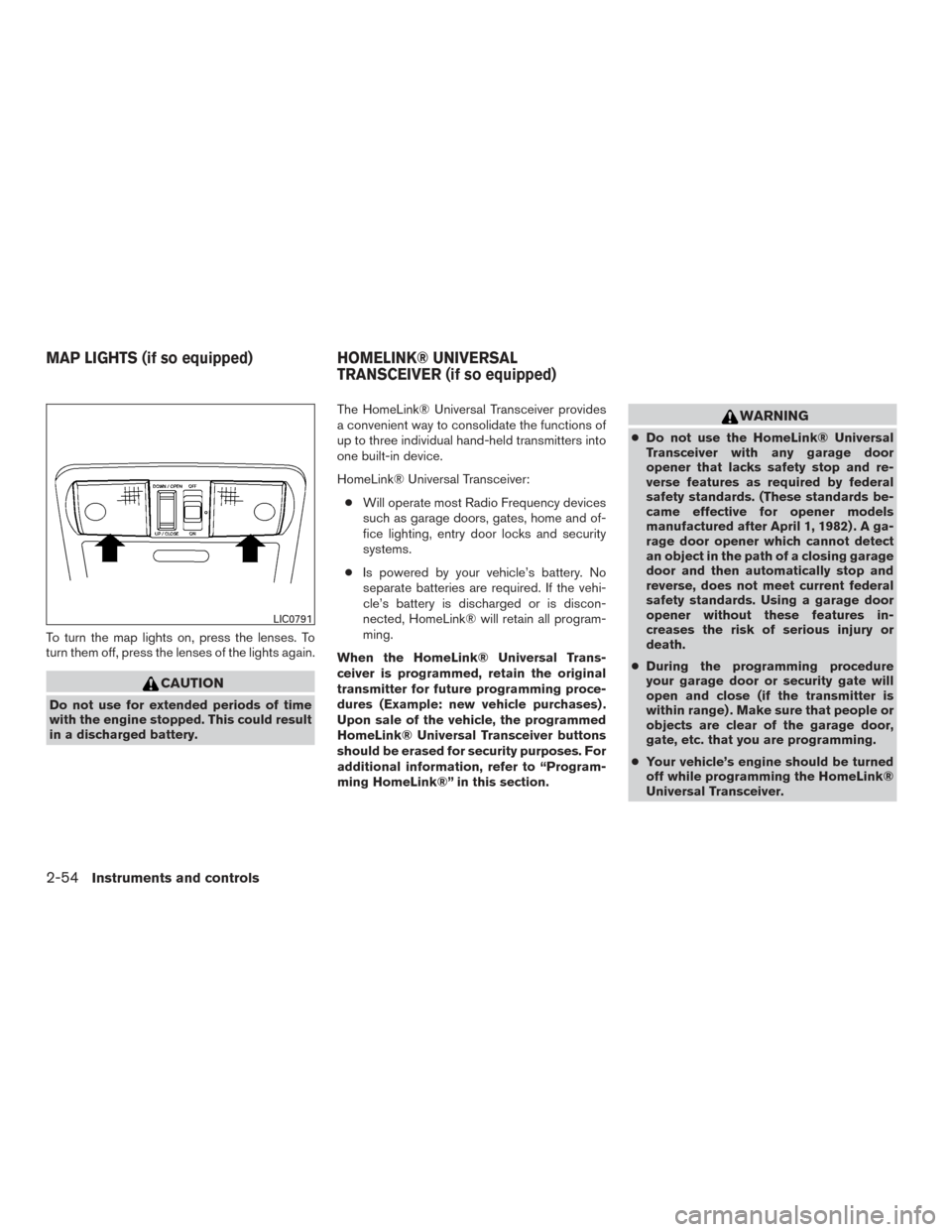
To turn the map lights on, press the lenses. To
turn them off, press the lenses of the lights again.
CAUTION
Do not use for extended periods of time
with the engine stopped. This could result
in a discharged battery.The HomeLink® Universal Transceiver provides
a convenient way to consolidate the functions of
up to three individual hand-held transmitters into
one built-in device.
HomeLink® Universal Transceiver:
● Will operate most Radio Frequency devices
such as garage doors, gates, home and of-
fice lighting, entry door locks and security
systems.
● Is powered by your vehicle’s battery. No
separate batteries are required. If the vehi-
cle’s battery is discharged or is discon-
nected, HomeLink® will retain all program-
ming.
When the HomeLink® Universal Trans-
ceiver is programmed, retain the original
transmitter for future programming proce-
dures (Example: new vehicle purchases) .
Upon sale of the vehicle, the programmed
HomeLink® Universal Transceiver buttons
should be erased for security purposes. For
additional information, refer to “Program-
ming HomeLink®” in this section.
WARNING
● Do not use the HomeLink® Universal
Transceiver with any garage door
opener that lacks safety stop and re-
verse features as required by federal
safety standards. (These standards be-
came effective for opener models
manufactured after April 1, 1982) . A ga-
rage door opener which cannot detect
an object in the path of a closing garage
door and then automatically stop and
reverse, does not meet current federal
safety standards. Using a garage door
opener without these features in-
creases the risk of serious injury or
death.
● During the programming procedure
your garage door or security gate will
open and close (if the transmitter is
within range) . Make sure that people or
objects are clear of the garage door,
gate, etc. that you are programming.
● Your vehicle’s engine should be turned
off while programming the HomeLink®
Universal Transceiver.
LIC0791
MAP LIGHTS (if so equipped) HOMELINK® UNIVERSAL
TRANSCEIVER (if so equipped)
2-54Instruments and controls
Page 185 of 466
TAILGATE
Opening the tailgate
Pull the tailgate handle upward and lower the
tailgate. The support cables hold the tailgate
open.
When closing the tailgate, make sure the latches
are securely locked.
Do not drive the vehicle with the tailgate
down, unless equipped with NISSAN’s Bed
Extender (accessory) or equivalent in the
extended position.For additional information on proper truck box
loading, refer to “Vehicle loading information” in
the “Technical and consumer information” sec-
tion of this manual.
WARNING
●
It is extremely dangerous to ride in a
cargo area inside a vehicle. In a colli-
sion, people riding in these areas are
more likely to be seriously injured or
killed.
● Do not allow people to ride in any area
of your vehicle that is not equipped with
seats and seat belts.
● Be sure everyone in your vehicle is in a
seat and using a seat belt properly.
LPD0270
TRUCK BOX
3-18Pre-driving checks and adjustments
Page 187 of 466
Removing the tailgate
1. Release the tailgate support cables.
CAUTION
●The tailgate is heavy. Two people
should remove or install it. Be careful
not to drop it during removal.
● After releasing the support cables, do
not let the tailgate rest on the bumper.
2. Hold the tailgate at a 15 degree angle.
3. Pull the tailgate out from the right side hinge.
4. Slide the tailgate out of the left side hinge.
Installing the tailgate
1. Insert the tailgate into the left side hinge.
2. Hold the tailgate at a 15 degree angle and insert into the right side hinge.
3. Continue to hold the tailgate at a 15 degree angle and attach the tailgate support cables.
4. Close the tailgate securely.
LPD2208
3-20Pre-driving checks and adjustments
Page 188 of 466
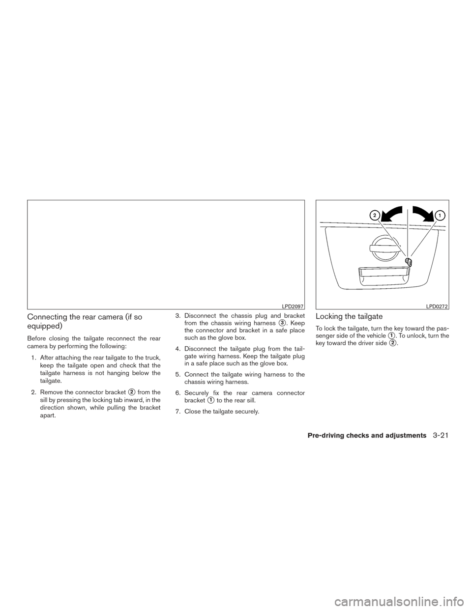
Connecting the rear camera (if so
equipped)
Before closing the tailgate reconnect the rear
camera by performing the following:1. After attaching the rear tailgate to the truck, keep the tailgate open and check that the
tailgate harness is not hanging below the
tailgate.
2. Remove the connector bracket
�2from the
sill by pressing the locking tab inward, in the
direction shown, while pulling the bracket
apart. 3. Disconnect the chassis plug and bracket
from the chassis wiring harness
�3. Keep
the connector and bracket in a safe place
such as the glove box.
4. Disconnect the tailgate plug from the tail- gate wiring harness. Keep the tailgate plug
in a safe place such as the glove box.
5. Connect the tailgate wiring harness to the chassis wiring harness.
6. Securely fix the rear camera connector bracket
�1to the rear sill.
7. Close the tailgate securely.
Locking the tailgate
To lock the tailgate, turn the key toward the pas-
senger side of the vehicle
�1. To unlock, turn the
key toward the driver side
�2.
LPD2097LPD0272
Pre-driving checks and adjustments3-21
Page 189 of 466
BED EXTENDER (if so equipped)
CAUTION
●Do not overload the bed extender.
Maximum load on the open tailgate is
200 lbs (890N) .
● Evenly distribute and properly secure
all cargo.
● Do not use the bed extender or tailgate
to secure cargo.
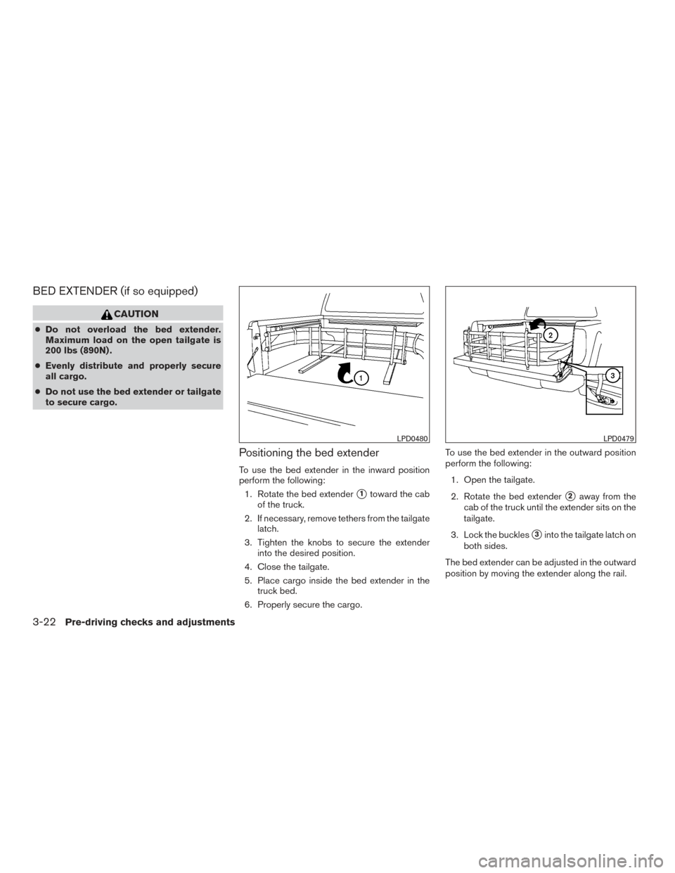
Positioning the bed extender
To use the bed extender in the inward position
perform the following:
1. Rotate the bed extender
�1toward the cab
of the truck.
2. If necessary, remove tethers from the tailgate latch.
3. Tighten the knobs to secure the extender into the desired position.
4. Close the tailgate.
5. Place cargo inside the bed extender in the truck bed.
6. Properly secure the cargo. To use the bed extender in the outward position
perform the following:
1. Open the tailgate.
2. Rotate the bed extender�2away from the
cab of the truck until the extender sits on the
tailgate.
3. Lock the buckles
�3into the tailgate latch on
both sides.
The bed extender can be adjusted in the outward
position by moving the extender along the rail.
LPD0480LPD0479
3-22Pre-driving checks and adjustments
Page 190 of 466
NOTE:
Use care when rotating extender, buckles
may come in contact with the truck bed
railing.
Removing and installing the bed
extender
To remove or install the bed extender perform the
following:1. Open the tailgate.
2. Rotate the bed extender into a vertical posi- tion and lift straight up (to remove) or lower
straight down (to install) .
To store the bed extender in the front of the truck
when not in use perform the following: 1. Position the sliding brackets past the center of the wheel well.
2. Re-install the extender into the brackets (see above) .
3. Rotate the extender to the inward position.
4. Push the brackets forward until the extender comes in contact with the front wall of the
truck box.
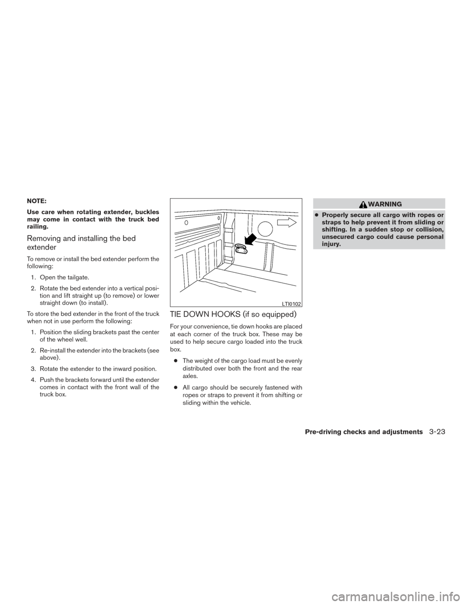
TIE DOWN HOOKS (if so equipped)
For your convenience, tie down hooks are placed
at each corner of the truck box. These may be
used to help secure cargo loaded into the truck
box.
● The weight of the cargo load must be evenly
distributed over both the front and the rear
axles.
● All cargo should be securely fastened with
ropes or straps to prevent it from shifting or
sliding within the vehicle.
WARNING
● Properly secure all cargo with ropes or
straps to help prevent it from sliding or
shifting. In a sudden stop or collision,
unsecured cargo could cause personal
injury.
LTI0102
Pre-driving checks and adjustments3-23
Page 201 of 466
When the shift lever is shifted into the R (Re-
verse) position, the monitor display shows the
view to the rear of the vehicle.
WARNING
Failure to follow the warnings and instruc-
tions for proper use of the RearView
Monitor could result in serious injury or
death.
●The RearView Monitor is a convenience
but it is not a substitute for proper back-
ing. Always turn and look out the win-
dows, and check mirrors to be sure that
it is safe to move before operating the
vehicle. Always back up slowly.
● The system is designed as an aid to the
driver in showing large stationary ob-
jects directly behind the vehicle, to help
avoid damaging the vehicle.
● The system cannot completely elimi-
nate blind spots and may not show ev-
ery object. ●
Underneath the bumper and the corner
areas of the bumper cannot be viewed
on the RearView Monitor because of its
monitoring range limitation. The system
will not show small objects below the
bumper, and may not show objects
close to the bumper or on the ground.
● Objects viewed in the RearView Moni-
tor differ from actual distance because
a wide-angle lens is used.
● Objects in a RearView Monitor will ap-
pear visually opposite than when
viewed in the rear view and outside
mirrors.
● Make sure that the tailgate is securely
closed when backing up.
● Do not put anything on the rearview
camera. The rearview camera is in-
stalled below the tailgate.
● When washing the vehicle with high
pressure water, be sure not to spray it
around the camera. Otherwise, water
may enter the camera unit causing wa-
ter condensation on the lens, a mal-
function, fire or an electric shock. ●
Do not strike the camera. It is a preci-
sion instrument. Otherwise, it may mal-
function or cause damage resulting in a
fire or an electric shock.CAUTION
There is a plastic cover over the camera.
Do not scratch the cover when cleaning
dirt or snow from the cover.
REARVIEW MONITOR (if so
equipped)
4-10Monitor, climate, audio, phone and voice recognition systems