Page 388 of 466

Vehicles operated in high temperatures or under
severe conditions require frequent checks of the
battery fluid level.
JUMP STARTING
If jump starting is necessary, refer to “Jump start-
ing” in the “In case of emergency” section of this
manual for additional information. If the engine
does not start by jump starting, the battery may
have to be replaced. Contact a NISSAN dealer.
CAUTION
●Do not ground accessories directly to
the battery terminal. Doing so will by-
pass the variable voltage control sys-
tem and the vehicle battery may not
charge completely.
● Use electrical accessories with the en-
gine running to avoid discharging the
vehicle battery. Your vehicle is equipped with a variable voltage
control system. This system measures the
amount of electrical discharge from the battery
and controls voltage generated by the generator.
The current sensor
�Ais located near the battery
along the negative battery cable. If you add elec-
trical accessories to your vehicle, be sure to
ground them to a suitable body ground such as
the frame or engine block area.
LDI0454
VARIABLE VOLTAGE CONTROL
SYSTEM
Maintenance and do-it-yourself8-19
Page 389 of 466
1. Power steering fluid pump pulley
2. Automatic belt tensioner pulley
3. Cooling fan pulley
4. Air conditioner compressor pulley
5. Crankshaft pulley
6. Generator pulley
WARNING
Be sure the ignition key is in the OFF or
LOCK position before servicing drive belt.
The engine could rotate unexpectedly.1. Visually inspect the belt for signs of unusual
wear, cuts, fraying or looseness. If the belt is
in poor condition or is loose, have it replaced
or adjusted by a NISSAN dealer.
2. Have the belt checked regularly for condi- tion and tension in accordance with the
maintenance schedule found in the
“NISSAN Service and Maintenance Guide”.
1. Power steering fluid pump pulley
2. Water pump pulley
3. Air conditioner compressor pulley (if so
equipped)
4. Crankshaft pulley
5. Generator pulley
VQ40DE
WDI0639
QR25DE
LDI0461
DRIVE BELT
8-20Maintenance and do-it-yourself
Page 395 of 466
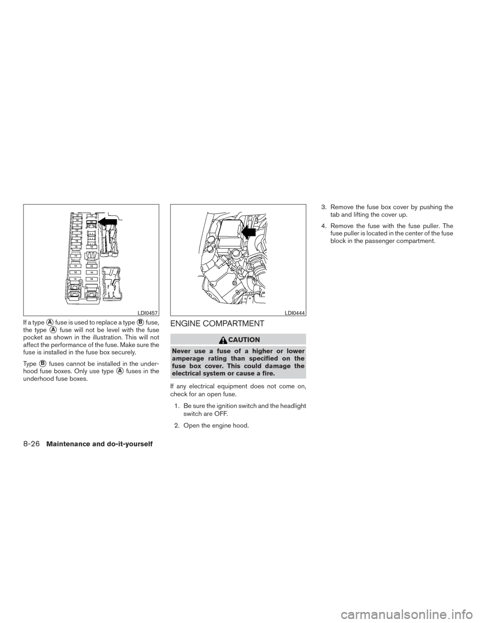
If a type�Afuse is used to replace a type�Bfuse,
the type
�Afuse will not be level with the fuse
pocket as shown in the illustration. This will not
affect the performance of the fuse. Make sure the
fuse is installed in the fuse box securely.
Type
�Bfuses cannot be installed in the under-
hood fuse boxes. Only use type
�Afuses in the
underhood fuse boxes.
ENGINE COMPARTMENT
CAUTION
Never use a fuse of a higher or lower
amperage rating than specified on the
fuse box cover. This could damage the
electrical system or cause a fire.
If any electrical equipment does not come on,
check for an open fuse. 1. Be sure the ignition switch and the headlight switch are OFF.
2. Open the engine hood. 3. Remove the fuse box cover by pushing the
tab and lifting the cover up.
4. Remove the fuse with the fuse puller. The fuse puller is located in the center of the fuse
block in the passenger compartment.
LDI0457LDI0444
8-26Maintenance and do-it-yourself
Page 398 of 466
How to remove the extended storage
switch:1. To remove the extended storage switch, be sure the ignition switch is in the OFF or
LOCK position.
2. Be sure the headlight switch is in the OFF position.
3. Remove the fuse box cover.
4. Pinch the locking tabs
�1found on each
side of the storage switch.
5. Pull the storage switch straight out from the fuse box
�2.
CAUTION
Be careful not to allow children to swallow
the battery or removed parts.
BATTERY REPLACEMENT
Maintenance and do-it-yourself8-29
Page 401 of 466
 battery cable.
3. Disconnect the electrical connector from therear end of the bulb. 4. Turn the bulb retaining ring
�Acount")
Removing the headlight bulb
1. Open the hood.
2. Disconnect the negative (-) battery cable.
3. Disconnect the electrical connector from therear end of the bulb. 4. Turn the bulb retaining ring
�Acounterclock-
wise until it is free from the headlight reflec-
tor and then remove it.
5. Carefully remove the headlight bulb. Do not shake or rotate the bulb
�Bwhen removing
it.
Replacing the headlight bulb
1. Insert the bulb.
DO NOT TOUCH THE BULB WITH BARE
HANDS.
2. Install and tighten the bulb retainer. ●Be sure the lip of the bulb socket con-
tacts the headlight body.
3. Push the electrical connector into the bulb plastic base until it snaps and stops.
4. Connect the negative (-) battery cable.
5. Close the hood.
FOG LIGHTS (if so equipped)
Replacing the fog light bulb (if so
equipped)
CAUTION
If replacement is required, see your
NISSAN dealer.
● High pressure halogen gas is sealed
inside the halogen bulb. The bulb may
break if the glass envelope is scratched
or the bulb is dropped.
● When handling the bulb, do not touch
the glass envelope.
● Use the same number and wattage as
originally installed as shown in the
chart.
● Do not leave the bulb out of the fog light
for a long period of time as dust, mois-
ture and smoke may enter the fog light
body and affect the performance of the
fog light.
LDI0446
8-32Maintenance and do-it-yourself
Page 419 of 466
Capacity (Approximate)Recommended Fluids and Lubricants
US measure Imp measure Liter
Rear final drive oil (except 6 speed M/T or
E-Lock vehicles) 3-3/8 pt
2-7/8 pt 1.6 L • API GL-5 synthetic gear oil, Viscosity SAE 75W-90
• See a NISSAN dealer for service for synthetic oil.
Rear final drive oil (6 speed M/T or E-Lock
vehicles) 4-1/4 pt
3-1/2 pt 2.0 L • Genuine NISSAN differential oil synthetic 75W-140 or API GL-5 syn-
thetic gear oil
• Viscosity SAE 75W-140
• See a NISSAN dealer for service for synthetic oil.
Windshield-washer fluid 1-1/4 gal1 gal4.5 L• Genuine NISSAN Windshield Washer Concentrate Cleaner & Antifreeze
or equivalent
9-4Technical and consumer information
Page 424 of 466
ENGINE
ModelQR25DE VQ40DE
Type Gasoline, 4-cycle, DOHC Gasoline, 4-cycle, DOHC
Cylinder arrangement 4-cylinder in-line6-cylinder, V-block, Slanted at 60°
Bore x Stroke in (mm) 3.5 x 3.9 (89.0 x 100.0)3.760 x 3.622 (95.5 x 92)
Displacement cu in (cm
3) 151.82 (2,488)241.30 (3,954)
Firing order 1–3–4–21–2–3–4–5–6
Idle speed
M/T
A/T in N (Neutral) position Refer to the “Emission control information label” on the underside of the hood.
Ignition timing (degree B.T.D.C. at idle
speed)
CO%atidle
Spark plug Standard PLZKAR6A-11DILFR5A-11
Spark plug gap (Nominal) in (mm) 0.043 (1.1)0.043 (1.1)
Camshaft operation Timing chainTiming chain
This spark ignition system complies with the Canadian standard ICES-002.
SPECIFICATIONS
Technical and consumer information9-9
Page 435 of 466
3. Insert the cleat into the channel perpendicu-lar to the channel as shown. Then rotate the
cleat clockwise 90° and slide it to the de-
sired location.
4. Position the cleat so the nubs on the bottomfully seat into the channel detents.
LTI0103
LTI0104
9-20Technical and consumer information


Recommended Fluids and Lubricants
US measure Imp measure Liter
Rear final drive oil (except 6 speed M/T or
E-Lock vehicles) 3-3/8 pt
2-7/8 pt 1.6 L • API GL-5 synthetic gear oi")
 3.5 x 3.9 (89.0 x 100.0")
