Page 424 of 510
WARNING
●To avoid the danger of being scalded,
never change the coolant when the en-
gine is hot.
● Never remove the radiator cap when the
engine is hot. Serious burns could be
caused by high pressure fluid escaping
from the radiator.
● Avoid direct skin contact with used
coolant. If skin contact is made, wash
thoroughly with soap or hand cleaner as
soon as possible.
● Keep coolant out of the reach of chil-
dren and pets.
Engine coolant must be disposed of properly.
Check your local regulations.
CHECKING ENGINE OIL LEVEL
1. Park the vehicle on a level surface and apply the parking brake.
2. Start the engine and let it idle until it reaches operating temperature.
3. Turn off the engine. Wait more than
10 minutes for the oil to drain back into
the oil pan.
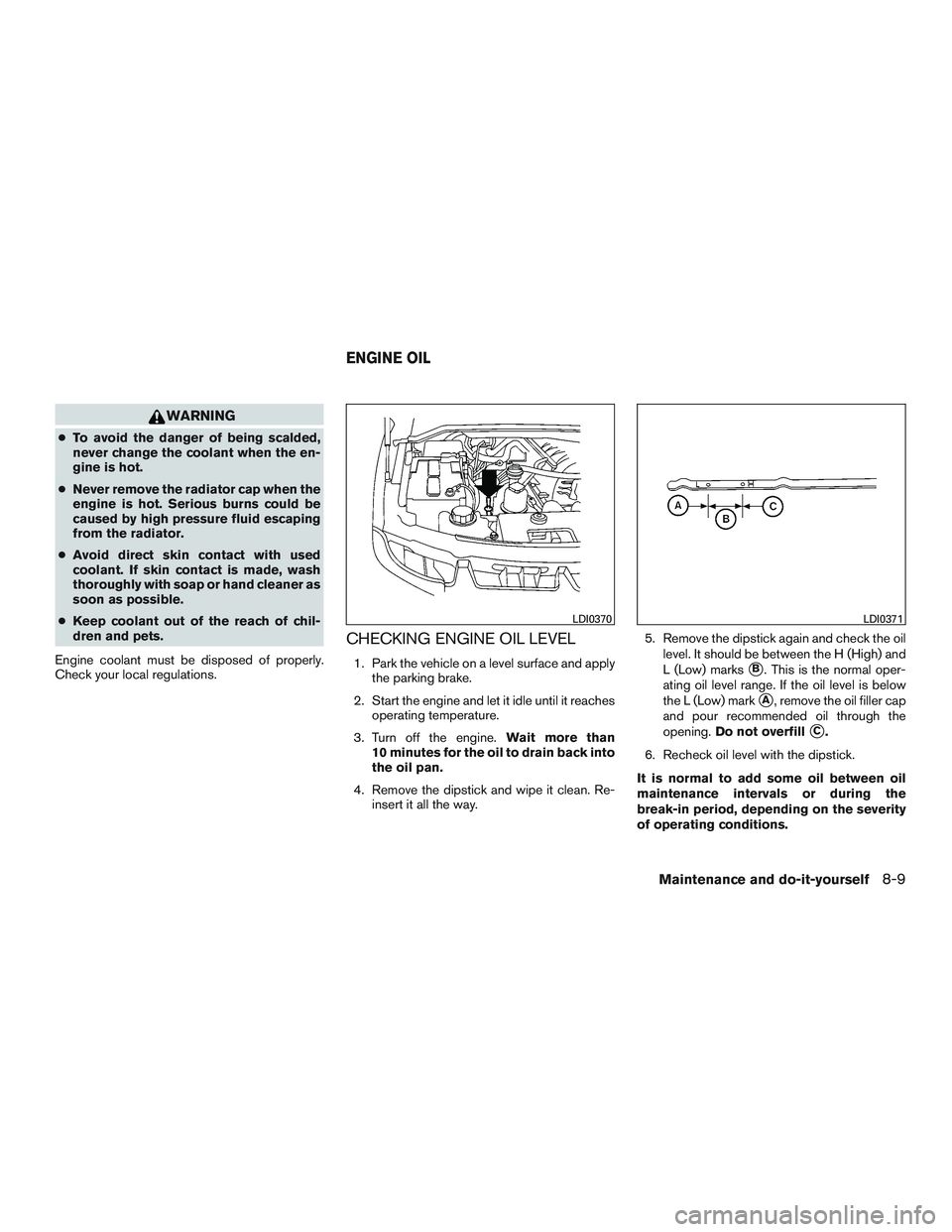
4. Remove the dipstick and wipe it clean. Re- insert it all the way. 5. Remove the dipstick again and check the oil
level. It should be between the H (High) and
L (Low) marks�B. This is the normal oper-
ating oil level range. If the oil level is below
the L (Low) mark
�A, remove the oil filler cap
and pour recommended oil through the
opening. Do not overfill
�C.
6. Recheck oil level with the dipstick.
It is normal to add some oil between oil
maintenance intervals or during the
break-in period, depending on the severity
of operating conditions.
Page 425 of 510
CAUTION
Oil level should be checked regularly. Op-
erating the engine with an insufficient
amount of oil can damage the engine, and
such damage is not covered by warranty.
CHANGING ENGINE OIL
1. Park the vehicle on a level surface and applythe parking brake.
2. Start the engine and let it idle until it reaches operating temperature, then turn it off. 3. Remove the oil filler cap
�Bby turning it
counterclockwise.
4. Place a large drain pan under the drain plug
�A.
5. Remove the drain plug
�Awith a wrench by
turning it counterclockwise and completely
drain the oil.
If the oil filter is to be changed, remove and
replace it at this time. For additional informa-
tion, refer to “Changing engine oil filter” in
this section.
● Waste oil must be disposed of prop-
erly.
● Check your local regulations.
Page 429 of 510
BRAKE FLUID
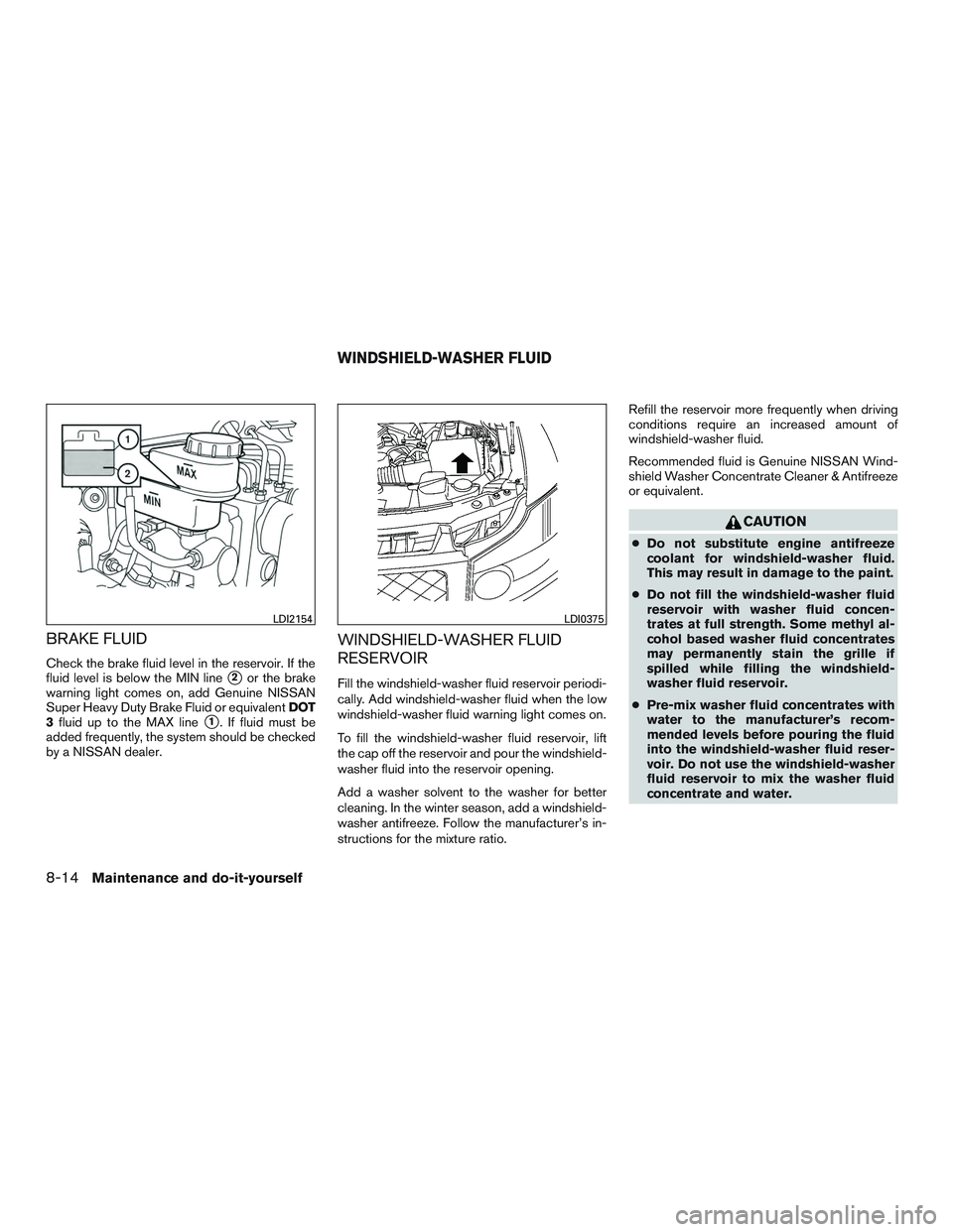
Check the brake fluid level in the reservoir. If the
fluid level is below the MIN line
�2or the brake
warning light comes on, add Genuine NISSAN
Super Heavy Duty Brake Fluid or equivalent DOT
3 fluid up to the MAX line
�1. If fluid must be
added frequently, the system should be checked
by a NISSAN dealer.
WINDSHIELD-WASHER FLUID
RESERVOIR
Fill the windshield-washer fluid reservoir periodi-
cally. Add windshield-washer fluid when the low
windshield-washer fluid warning light comes on.
To fill the windshield-washer fluid reservoir, lift
the cap off the reservoir and pour the windshield-
washer fluid into the reservoir opening.
Add a washer solvent to the washer for better
cleaning. In the winter season, add a windshield-
washer antifreeze. Follow the manufacturer’s in-
structions for the mixture ratio. Refill the reservoir more frequently when driving
conditions require an increased amount of
windshield-washer fluid.
Recommended fluid is Genuine NISSAN Wind-
shield Washer Concentrate Cleaner & Antifreeze
or equivalent.
Page 439 of 510
If the brakes do not operate properly, have the
brakes checked by a NISSAN dealer.
Self-adjusting brakes
Your vehicle is equipped with self-adjusting
brakes.
The front and rear disc-type brakes self-adjust
every time the brake pedal is applied.
Page 487 of 510
A weight-distributing hitch system (Class IV) is
recommended if you plan to tow trailers with a
maximum weight over 5,000 lbs (2,268 kg).
Check with the trailer and towing equipment
manufacturers to determine if they recommend
the use of a weight-distributing hitch system.
NOTE:
A weight-distributing hitch system may af-
fect the operation of trailer surge brakes. If
you are considering use of a weight-
distributing hitch system with a surge
brake-equipped trailer, check with the
surge brake, hitch or trailer manufacturer
to determine if and how this can be done.
Follow the instructions provided by the manufac-
turer for installing and using the weight-
distributing hitch system.
General set-up instructions are as follows:1. Park unloaded vehicle on a level surface. With the ignition on and the doors closed,
allow the vehicle to stand for several minutes
so that it can level.
2. Measure the height of a reference point on the front and rear bumpers at the center of
the vehicle. 3. Attach the trailer to the vehicle and adjust
the hitch equalizers so that the front bumper
height is within0-.5inches (0 – 13 mm) of
the reference height measured in step 2. The
rear bumper should be no higher than the
reference height measured in step 2.
Page 488 of 510
CAUTION
●Special hitches which include frame re-
inforcements are required for towing
above 2,000 lb (907 kg) . Suitable genu-
ine NISSAN hitches, ball mounts and
hitch balls for pickup trucks and sport
utility vehicles are available at a
NISSAN dealer.
● The hitch should not be attached to or
affect the operation of the impact-
absorbing bumper.
● Do not use axle-mounted hitches.
● Do not modify the vehicle exhaust sys-
tem, brake system, etc. to install a
trailer hitch.
● To reduce the possibility of additional
damage if your vehicle is struck from
the rear, where practical, remove the
receiver when not in use.
● Regularly check that all trailer hitch
mounting bolts are securely mounted.
Tire pressures
● When towing a trailer, inflate the ve-
hicle tires to the recommended cold
tire pressure indicated on the Tire
and Loading Information label.
● Trailer tire condition, size, load rating
and proper inflation pressure should
be in accordance with the trailer and
tire manufacturer’s specifications.
Safety chains
Always use suitable safety chains between your
vehicle and the trailer. The safety chains should
be crossed and should be attached to the hitch,
not to the vehicle bumper or axle. The safety
chains can be attached to the bumper if the hitch
ball is mounted to the bumper. Be sure to leave
enough slack in the chains to permit turning
corners.
Trailer lights
Page 489 of 510
Trailer brakes
When towing a trailer load of 3,500 lbs.
(1,587 kg) or more, trailers with a brake
system MUST be used.However, most states
require a separate braking system on trailers with
a loaded weight above a specific amount. Make
sure the trailer meets the local regulations and
the regulations where you plan to tow.
Several types of braking systems are available.
Surge Brakes - The surge brake actuator is
mounted on the trailer tongue with a hydraulic line
running to each trailer wheel. Surge brakes are
activated by the trailer pushing against the hitch
ball when the tow vehicle is braking. Hydraulic
surge brakes are common on rental trailers and
some boat trailers. In this type of system, there is
no hydraulic or electric connection for brake op-
eration between the tow vehicle and the trailer.
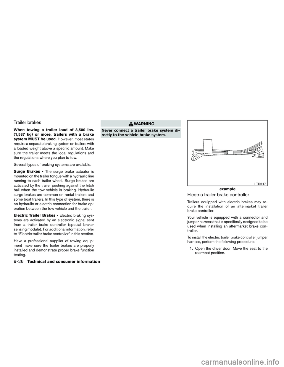
Electric Trailer Brakes - Electric braking sys-
tems are activated by an electronic signal sent
from a trailer brake controller (special brake-
sensing module) . For additional information, refer
to “Electric trailer brake controller” in this section.
Have a professional supplier of towing equip-
ment make sure the trailer brakes are properly
installed and demonstrate proper brake function
testing.
Page 502 of 510
Extendedstorageswitch ............8-28
Eyeglass case..................2-47
F
Flashers (See hazard warning flasher switch) . .6-2
Flat tire ....................6-2,6-3
Floor mat positioning aid .............7-5
Fluid Brake fluid ..................8-13
Capacities and recommended
fuel/lubricants .................9-2
Engine coolant .................8-7
Engine oil ...................8-9
Power steering fluid .............8-13
Windshield-washerfluid...........8-14
F.M.V.S.S. certification label ...........9-12
Foglightswitch .................2-38
Front air bag system
(See supplemental restraint system) ......1-62
Front and rear sonar system ..........5-36
Front power seat adjustment ...........1-3
Frontseats.....................1-2
Fuel Capacities and recommended
fuel/lubricants .................9-2
Fuel economy ................5-23
Fuel gauge ...................2-6
Fuel octane rating ...............9-5
Fuel recommendation .............9-4
Loose fuel cap warning ........2-28,3-28
Fuel Cell Vehicle (FCV) System Tirepressure.................8-37
Fuel-filler door ..................3-28
Fuel gauge .....................2-6 Fuses.......................8-24
Fusiblelinks ...................8-26
G
Garage door opener, HomeLink® Universal
Transceiver .........2-64,2-65,2-66,2-67
Gauge Automatic transmission fluid temperature
gauge .....................2-8
Engine coolant temperature gauge .....2-5
Engine oil pressure gauge ..........2-7
Fuel gauge ...................2-6
Odometer ...................2-4
Speedometer .................2-4
Tachometer ..................2-5
Trip odometer .................2-4
Voltmeter....................2-7
General maintenance ...............8-2
Glass hatch ...................3-28
Glovebox.....................2-47
Gloveboxlock..................2-47
H
Hands-free phone system,
Bluetooth®...............4- 108, 4-122
Hazard warning flasher switch ..........6-2
Headlight and turn signal switch ........2-34
Headlight control switch ............2-35
Headlights ....................8-31
Head restraints ..................1-14
Heated seats ...............2-39,2-40
Heated steering wheel .............2-41 Heater
Heater and air conditioner controls .....4-29
Heater operation ...............4-30
Rear seat air conditioner ..........4-31
HomeLink® Universal
Transceiver .........2-64,2-65,2-66,2-67
H
ood.......................3-23
Hook Luggage hook ................2-53
Horn .......................2-38
I
Ignition switch ...................5-9
Imageviewer...................4-19
Immobilizer system .........2-30,3-4,5-12
Important vehicle information label .......9-12
In-cabin microfilter ................8-19
Increasing fuel economy .............5-23
Indicator lights and audible reminders
(See warning/indicator lights and
audible reminders) .........2-12,2-13,2-18
Information display ................2-21
Inside automatic anti-glare mirror ........3-33
Instrument brightness control ..........2-37
Instrumentpanel...............0-6,2-2
Instrument panel dimmer switch ........2-37
Intelligent Key system Key operating range .............3-14
Key operation ................3-15
Mechanical key ................3-3
Remote keyless entry operation.......3-17
Troubleshooting guide ............3-22
Warning signals ...............3-22
Interior light ....................2-62
10-3