2015 NISSAN ARMADA power steering
[x] Cancel search: power steeringPage 16 of 510
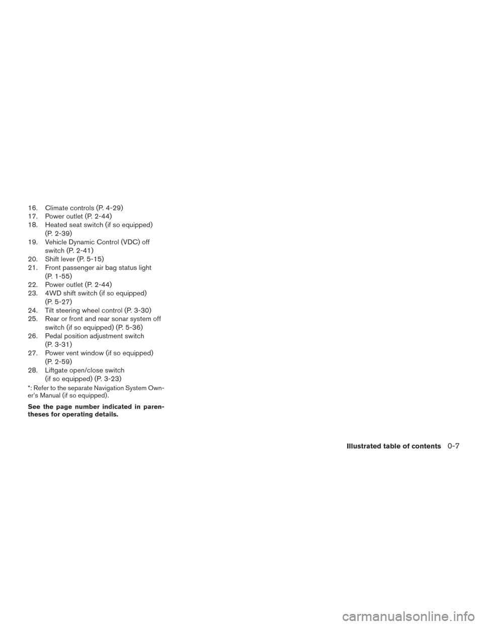
16. Climate controls (P. 4-29)
17. Power outlet (P. 2-44)
18. Heated seat switch (if so equipped)(P. 2-39)
19. Vehicle Dynamic Control (VDC) off
switch (P. 2-41)
20. Shift lever (P. 5-15)
21. Front passenger air bag status light
(P. 1-55)
22. Power outlet (P. 2-44)
23. 4WD shift switch (if so equipped)
(P. 5-27)
24. Tilt steering wheel control (P. 3-30)
25. Rear or front and rear sonar system off
switch (if so equipped) (P. 5-36)
26. Pedal position adjustment switch
(P. 3-31)
27. Power vent window (if so equipped)
(P. 2-59)
28. Liftgate open/close switch
(if so equipped) (P. 3-23)
*: Refer to the separate Navigation System Own-
er’s Manual (if so equipped) .
See the page number indicated in paren-
theses for operating details.
Illustrated table of contents0-7
Page 17 of 510
1. Battery (P. 8-15)
2. Fuse/fusible link box (P. 8-24)
3. Engine oil filler cap (P. 8-9)
4. Brake fluid reservoir (P. 8-13)
5. Windshield-washer fluid reservoir(P. 8-14)
6. Air cleaner (P. 8-19)
7. Drive belt location (P.8-17)
8. Radiator cap (P. 8-7)
9. Power steering fluid reservoir (P. 8-13)
10. Engine oil dipstick (P. 8-9)
11. Engine coolant reservoir (P. 8-7)
Refer to the page number indicated in pa-
rentheses for operating details.
LDI2482
ENGINE COMPARTMENT CHECK
LOCATIONS
0-8Illustrated table of contents
Page 95 of 510
2 Instruments and controls
Instrument panel...................................2-2
Meters and gauges ................................2-3
Speedometer and odometer .....................2-4
Tachometer ....................................2-5
Engine coolant temperature gauge ...............2-5
Fuel gauge ....................................2-6
Engine oil pressure gauge .......................2-7
Voltmeter ......................................2-7
Automatic transmission fluid temperature
gauge .........................................2-8
Compass display (if so equipped) ...................2-8
Compass display ...............................2-9
Warning/indicator lights and audible reminders ......2-12
Checking bulbs ............................... 2-13
Warning lights ................................ 2-13
Indicator lights ................................ 2-18
Audible reminders ............................. 2-20
Vehicle Information Display ........................2-21
How to use the Vehicle Information Display .......2-21
Security systems ................................. 2-29
Vehicle security system ......................... 2-29
NISSAN vehicle immobilizer system .............2-30
Windshield wiper and washer switch ...............2-32Switch operation
.............................. 2-32
Rear window wiper and washer switch ..............2-33
Rear window and outside mirror defroster switch .....2-34
Headlight and turn signal switch ....................2-34
Headlight control switch ........................ 2-35
Daytime running light system (Canada only) ......2-36
Instrument brightness control ...................2-37
Turn signal switch ............................. 2-37
Fog light switch (if so equipped) ................2-38
Horn ............................................ 2-38
Heated seats (if so equipped) ......................2-39
Heated rear seats (if so equipped) ..................2-40
Heated steering wheel (if so equipped) .............2-41
Vehicle Dynamic Control (VDC) off switch ...........2-41
Rear sonar system off switch (if so equipped) ........2-42
Front and rear sonar system off switch (if so
equipped) ....................................... 2-42
T
ow mode switch ................................. 2-43
Power outlet ..................................... 2-44
Storage ......................................... 2-45
Map pockets .................................. 2-45
Seatback pocket .............................. 2-45
Instrument panel storage trays ..................2-46
Page 98 of 510
16. Climate controls (P. 4-29)
17. Power outlet (P. 2-44)
18. Heated seat switch (if so equipped)(P. 2-39)
19. Vehicle Dynamic Control (VDC) off
switch (P. 2-41)
20. Shift lever (P. 5-15)
21. Front passenger air bag status light
(P. 1-55)
22. Power outlet (P. 2-44)
23. 4WD shift switch (if so equipped)
(P. 5-27)
24. Tilt steering wheel control (P. 3-30)
25. Rear or front and rear sonar system off
switch (if so equipped) (P. 5-36)
26. Pedal position adjustment switch
(P. 3-31)
27. Power vent window (if so equipped)
(P. 2-59)
28. Liftgate open/close switch
(if so equipped) (P. 3-23)
*: Refer to the separate Navigation System Own-
er’s Manual (if so equipped) .
See the page number indicated in paren-
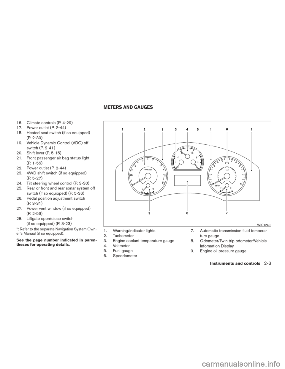
theses for operating details.1. Warning/indicator lights
2. Tachometer
3. Engine coolant temperature gauge
4. Voltmeter
5. Fuel gauge
6. Speedometer 7. Automatic transmission fluid tempera-
ture gauge
8. Odometer/Twin trip odometer/Vehicle
Information Display
9. Engine oil pressure gauge
WIC1243
METERS AND GAUGES
Instruments and controls2-3
Page 136 of 510
The heated steering wheel system is designed to
operate only when the surface temperature of the
steering wheel is below approximately 68°F
(20°C) .
Push the heated steering wheel switch to warm
the steering wheel after the engine starts. The
indicator light will come on.
If the surface temperature of the steering wheel is
below 68°F (20°C) , the system will heat the
steering wheel to approximately 86°F (30°C) ,
then turn off automatically.
Push the switch again to turn the heated steering
wheel off manually. The indicator light will go off.NOTE:
The heated steering wheel switch is
equipped with a 30 minute timer. After the
switch has been activated for 30 minutes,
the system will automatically turn off. If the
surface temperature of the steering wheel
is above 68°F (20°C) when the switch is
turned on, the system will not heat the
steering wheel. This is not a malfunction.
The vehicle should be driven with the VDC sys-
tem on for most driving conditions.
If the vehicle is stuck in mud or snow, the VDC
system reduces the engine output to reduce
wheel spin. The engine speed will be reduced
even if the accelerator is depressed to the floor. If
maximum engine power is needed to free a stuck
vehicle, turn the VDC system off.
To turn off the VDC system, push the VDC OFF
switch. The
indicator will come on.
Push the VDC OFF switch again or restart the
engine to turn on the system. For additional infor-
mation, refer to “Vehicle Dynamic Control (VDC)
system” in the “Starting and driving” section of
this manual.
LIC0421LIC1548
HEATED STEERING WHEEL (if so
equipped) VEHICLE DYNAMIC CONTROL (VDC)
OFF SWITCH
Instruments and controls2-41
Page 164 of 510
3 Pre-driving checks and adjustments
Keys .............................................3-2NISSAN Intelligent Key® (if so equipped) .........3-2
NISSAN Vehicle Immobilizer System keys .........3-4
Doors ............................................3-5
Locking with key ................................3-5
Locking with inside lock knob ....................3-6
Locking with power door lock switch . . . ..........3-6
Automatic door locks ...........................3-6
Child safety rear door lock .......................3-7
Remote keyless entry system (if so equipped) .........3-7
How to use remote keyless entry system ..........3-8
NISSAN Intelligent Key® (if so equipped) ...........3-12
Operating range ............................... 3-14
Door locks/unlocks precaution ..................3-14
NISSAN Intelligent Key® Operation .............3-15
How to use the remote keyless entry
function ...................................... 3-17
Warning signals ............................... 3-21
Troubleshooting guide ......................... 3-22
Hood ........................................... 3-23
Liftgate .......................................... 3-23Operating the manual liftgate (if so
equipped)
.................................... 3-24
Operating the power liftgate (if so equipped) .....3-24
Cancel switch ................................. 3-26
Liftgate release ................................ 3-27
Glass hatch ...................................... 3-28
Fuel-filler door ................................... 3-28
Fuel-filler cap ................................. 3-28
Steering wheel ................................... 3-30
Tilt operation .................................. 3-30
Pedal position adjustment ......................... 3-31
Sun visors ....................................... 3-32
Vanity mirrors ................................. 3-32
Mirrors .......................................... 3-33
Rearview mirror (if so equipped) .................3-33
Automatic anti-glare rearview mirror
(if so equipped) ............................... 3-33
Outside mirrors ............................... 3-34
Automatic drive positioner (if so equipped) ..........3-36
Memory
storage function ....................... 3-36
Entry/exit function ............................. 3-37
System operation .............................. 3-38
Page 175 of 510
WARNING
●Radio waves could adversely affect
electric medical equipment. Those who
use a pacemaker should contact the
electric medical equipment manufac-
turer for the possible influences before
use.
● The Intelligent Key transmits radio
waves when the buttons are pressed.
The FAA advises the radio waves may
affect aircraft navigation and communi-
cation systems. Do not operate the In-
telligent Key while on an airplane. Make
sure the buttons are not operated unin-
tentionally when the unit is stored for a
flight.
The Intelligent Key can operate all the door locks
using the remote control function or pushing the
request switch on the vehicle without taking the
key out from a pocket or purse. The operating
environment and/or conditions may affect the
Intelligent Key operation.
Be sure to read the following before using the
Intelligent Key.
CAUTION
● Be sure to carry the Intelligent Key with
you when operating the vehicle.
● Never leave the Intelligent Key in the
vehicle when you leave the vehicle.
The Intelligent Key is always communicating with
the vehicle as it receives radio waves. The Intel-
ligent Key transmits weak radio waves. Environ-
mental conditions may interfere with the opera-
tion of the Intelligent Key under the following
operating conditions. ●
When operating near a location where strong
radio waves are transmitted, such as a TV
tower, power station and broadcasting station.
● When in possession of wireless equipment,
such as a cellular telephone, transceiver,
and CB radio.
● When the Intelligent Key is in contact with or
covered by metallic materials.
● When any type of radio wave remote control
is used nearby.
● When the Intelligent Key is placed near an
electric appliance such as a personal com-
puter.
● When the vehicle is parked near a parking
meter. In such cases, correct the operating conditions
before using the Intelligent Key function or use
the mechanical key.
Although the life of the battery varies depending
on the operating conditions, the battery’s life is
approximately two years. If the battery is dis-
charged, replace it with a new one.
When the Intelligent Key battery is low, the Intel-
ligent Key indicator will illuminate after the ignition
switch is placed in the ON position.
Since the Intelligent Key is continuously receiving
radio waves, if the key is left near equipment
which transmits strong radio waves, such as sig-
nals from a TV and personal computer, the bat-
tery life may become shorter.
For additional information regarding replacement
of a battery, refer to “Battery replacement” in the
“Maintenance and do-it-yourself” section of this
manual.
For models with a steering wheel lock mecha-
nism: Because the steering wheel is locked elec-
trically, unlocking the steering wheel with the
ignition switch in the LOCK position is impossible
when the vehicle battery is completely dis-
charged. Unlocking the steering wheel is impos-
sible even if the Intelligent Key is inserted into the
ignition switch. Pay special attention that the
vehicle battery is not completely discharged.
NISSAN INTELLIGENT KEY® (if so
equipped)
3-12Pre-driving checks and adjustments
Page 282 of 510
●A new disc may be rough on the inner and
outer edges. Remove the rough edges by
rubbing the inner and outer edges with the
side of a pen or pencil as illustrated.
STEERING WHEEL SWITCH FOR
AUDIO CONTROL
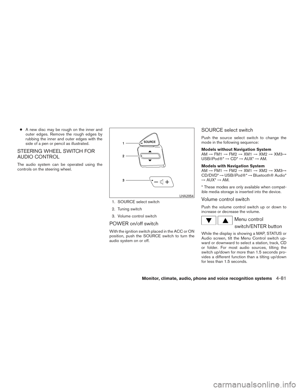
The audio system can be operated using the
controls on the steering wheel.
1. SOURCE select switch
2. Tuning switch
3. Volume control switch
POWER on/off switch
With the ignition switch placed in the ACC or ON
position, push the SOURCE switch to turn the
audio system on or off.
SOURCE select switch
Push the source select switch to change the
mode in the following sequence:
Models without Navigation System
AM→FM1 →FM2 →XM1 →XM2 →XM3→
USB/iPod®* →CD* →AUX* →AM.
Models with Navigation System
AM →FM1 →FM2 →XM1 →XM2 →XM3→
CD/DVD* →USB/iPod®* →Bluetooth® Audio*
→ AUX* →AM.
* These modes are only available when compat-
ible media storage is inserted into the device.
Volume control switch
Push the volume control switch up or down to
increase or decrease the volume.
Menu control switch/ENTER button
While the display is showing a MAP, STATUS or
Audio screen, tilt the Menu Control switch up-
ward or downward to select a station, track, CD
or folder. For most audio sources, tilting the
switch up/down for more than 1.5 seconds pro-
vides a different function than a tilting up/down
for less than 1.5 seconds.
LHA2054
Monitor, climate, audio, phone and voice recognition systems4-81