2015 MITSUBISHI OUTLANDER SPORT tire size
[x] Cancel search: tire sizePage 241 of 384
Loading information 6-8 Driving safety
6
Occupant distribution: Occupant distribu- tion within the passenger compartment (In your vehicle the distribution is 2 in front, 1 in second row seat)
N00630100383
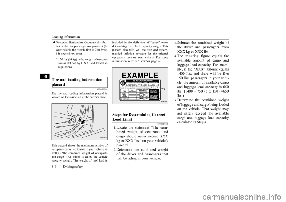
The tire and loading information placard islocated on the inside sill of the driver’s door. This placard shows the maximum number of occupants permitted to ride in your vehicle as well as “the combined weight of occupantsand cargo” (A), which is called the vehicle capacity weight. The weight of roof load is
included in the definition of “cargo” when determining the vehicle capacity weight. This placard also tells you the size and recom- mended inflation pressure for the originalequipment tires on your vehicle. For more information, refer to “Tires” on page 9-13.
N00630201251
1.Locate the statement “The com- bined weight of occupants andcargo should never exceed XXX kg or XXX lbs.” on your vehicle’s placard.2.Determine the combined weight of the driver and passengers that will be riding in your vehicle.
3.Subtract the combined weight of the driver and passengers from XXX kg or XXX lbs.4.The resulting figure equals theavailable amount of cargo andluggage load capacity. For exam- ple, if the “XXX” amount equals 1400 lbs. and there will be five150 lbs. passengers in your vehi- cle, the amount of available cargo and luggage load capacity is 650lbs. (1400 - 750 (5 x 150) =650 lbs.)5.Determine the combined weight of luggage and cargo being loaded on the vehicle. That weight may not safely exceed the availablecargo and luggage load capacity calculated in Step 4.
* :150 lbs (68 kg) is the weight of one per- son as defined by U.S.A. and Canadian regulations.
Tire and loading information placard
Steps for Determining Correct Load Limit
BK0206700US.bo
ok 8 ページ 2014年3月25日 火曜日 午後4時42分
Page 314 of 384
How to change a tire
For emergencies 8-7
8
N00849700273
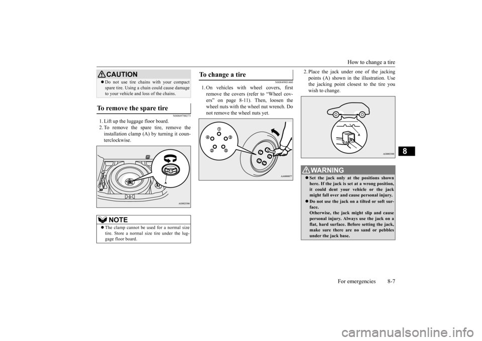
1. Lift up the luggage floor board. 2. To remove the spare tire, remove theinstallation clamp (A) by turning it coun-terclockwise.
N00849801460
1. On vehicles with wheel covers, firstremove the covers (refer to “Wheel cov-ers” on page 8-11). Then, loosen the wheel nuts with the wheel nut wrench. Do not remove the wheel nuts yet.
2. Place the jack under
one of the jacking
points (A) shown in the illustration. Use the jacking point closest to the tire you wish to change.
Do not use tire chains with your compact spare tire. Using a chain could cause damage to your vehicle and loss of the chains.
To remove the spare tire
NOTE
The clamp cannot be used for a normal size tire. Store a normal size tire under the lug- gage floor board.CAUTION
To change a tire
WA R N I N G Set the jack only at the positions shown here. If the jack is set at a wrong position, it could dent your vehicle or the jack might fall over and cause personal injury. Do not use the jack on a tilted or soft sur- face.Otherwise, the jack might slip and cause personal injury. Always use the jack on a flat, hard surface. Before setting the jack,make sure there are no sand or pebbles under the jack base.
BK0206700US.bo
ok 7 ページ 2014年3月25日 火曜日 午後4時42分
Page 317 of 384

How to change a tire 8-10 For emergencies
8
8. Lower the vehicle slowly until the tire touches the ground, by rotating the wheel nut wrench counterclockwise. 9. Tighten the nuts in the order shown in the illustration until each nut has been tight- ened to the torque listed here.65 to 80 ft-lb (88 to 108 N•m)
10. Lower the jack all the way and remove it. 11. Check the tire inflation pressure. The rec-
ommended tire pressure for your vehicle is listed on the tire and loading informa-tion placard attached to the driver’s doorsill as shown in the illustration. Refer to “Tire inflation pressures” on page 9-17.
N00850000162
Reverse the removing procedure when stor- ing the flat tire or spare tire, jack, bar and wheel nut wrench. Refer to “To remove the spare tire” on page8-7 and “Jack and tools” on page 8-5.
CAUTION Never use your foot or a pipe extension to apply added force to the wheel nut wrench when tightening the wheel nuts. If you do so, you can over-tighten the wheel nuts and damage the wheel, wheel nuts and hub bolts.
CAUTION Driving with an improperly inflated tire can cause an accident. If
you have no choice but
to drive with an under-inflated tire, keep your speed down and avoid sudden steering or braking, if possible
. Inflate the tire to the
correct pressure as soon as possible. Refer to “Tire inflation pressures” on page 9-17. After changing the tire and driving the vehi- cle about 620 miles (1,000 km), retighten the wheel nuts to make sure that they have notcome loose. If the steering wheel vibrates when driving after changing the tire, have the tire checked for balance at an authorized Mitsubishi Motors dealer or a repair facility of yourchoice. Do not mix one type of tire with another or use a different size from the one listed. This would cause early wear and poor handling.
To store the flat tire or spare tire, jack, bar and wheel nut wrench
BK0206700US.bo
ok 10 ページ 2014年3月25日 火曜日 午後4時42分
Page 337 of 384
Tires 9-14 Vehicle care and maintenance
9
Cold tire pressure: • The measured pressure after the vehicle has been parked for at least three hours, or• The measured pressure when the vehicle is driven less than 1 mile (1.6 km) after having been parked for three hours.
Maximum pressure:the maximum permis- sible cold tire inflat
ion pressure for this
tire. Recommended inflation pressure: the inflation pressure for optimum tire perfor- mance. Intended outboard sidewall: • The sidewall that contains a whitewall, bears white lettering or bears manufac- turer, brand, and/or model name moldingthat is higher or deeper than the same molding on the other sidewall of the tire, or• The outward facing sidewall of an asym- metrical tire that has a particular side that must always face outward whenmounted on a vehicle.
Passenger car tire: a tire intended for use on passenger cars, multipurpose passen-ger vehicles, and trucks, that have a gross vehicle weight rating (GVWR) of 10,000 pounds or less.
Light truck (LT) tire: a tire designated by its manufacturer as primarily intended for use on lightweight trucks or multipurpose passenger vehicles. Tread: portion of a tire that comes into contact with the road. Tread rib: a tread section running circum- ferentially around a tire. Tread separation: pulling away of the tread from the tire carcass. Carcass: the tire structure, except tread and sidewall rubber which, when inflated, bears the load. Sidewall: portion of a tire between the tread and bead. Section width: the linear distance between the exteriors of the sidewalls of aninflated tire, excluding elevations due to labeling, decoration, or protective bands. Bead: the part of the tire that is made of steel wires, wrapped or reinforced by ply cords and that is shaped to fit the rim. Ply: a layer of rubber-coated parallel cords. Cord: the strands forming the plies in the tire. Rim: a metal support for a tire or a tire and tube assembly upon which the tire beads are seated. Rim diameter: nominal diameter of the bead seat.
Groove: the space between two adjacent tread ribs.
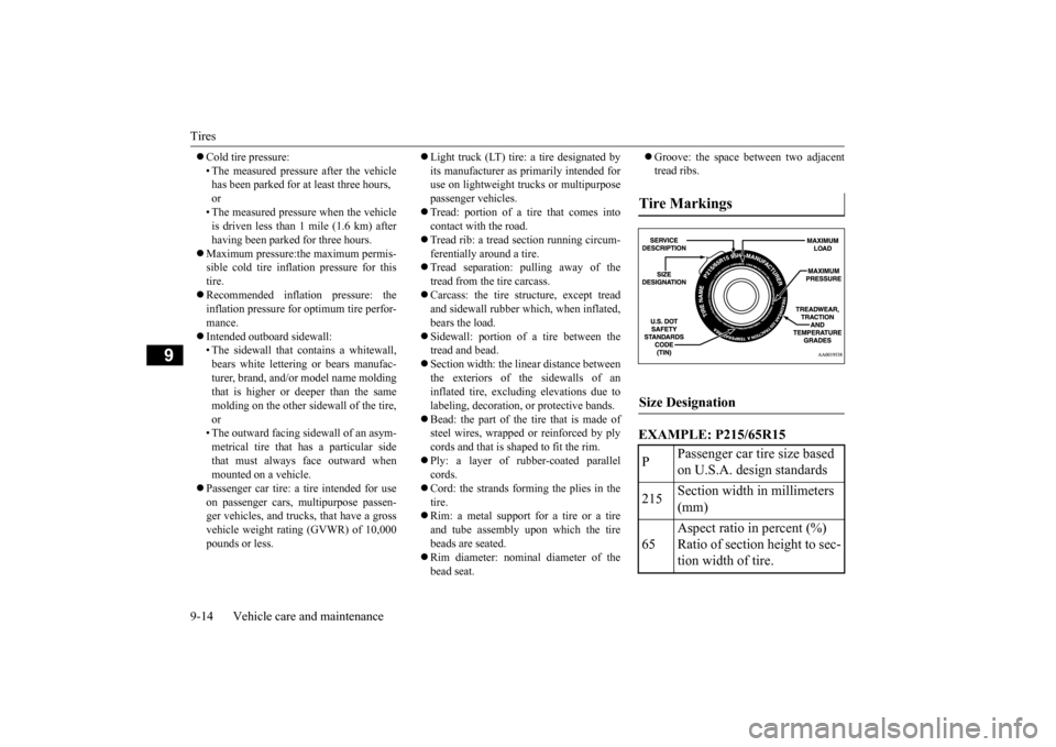
EXAMPLE: P215/65R15Tire Markings Size Designation P
Passenger car tire size based on U.S.A. design standards
215
Section width in millimeters (mm)
65
Aspect ratio in percent (%) Ratio of section height to sec- tion width of tire.
BK0206700US.bo
ok 14 ページ 2014年3月25日 火曜日 午後4時42分
Page 338 of 384
Tires
Vehicle care and maintenance 9-15
9
EXAMPLE: 95H
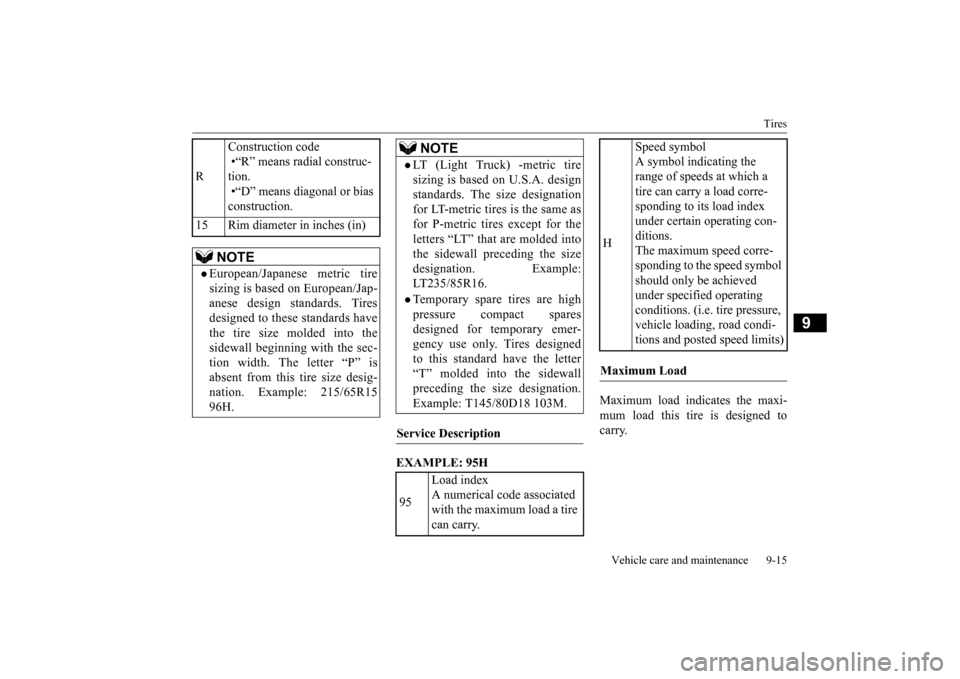
Maximum load indicates the maxi- mum load this tire is designed to carry.
R
Construction code •“R” means radial construc- tion. •“D” means diagonal or bias construction.
15 Rim diameter in inches (in)
NOTE
European/Japanese metric tire sizing is based on European/Jap- anese design standards. Tiresdesigned to these standards have the tire size molded into the sidewall beginning with the sec-tion width. The letter “P” is absent from this tire size desig- nation. Example: 215/65R1596H.
LT (Light Truck) -metric tire sizing is based on U.S.A. design standards. The size designationfor LT-metric tires is the same as for P-metric tires except for the letters “LT” that are molded intothe sidewall preceding the size designation. Example: LT235/85R16.Temporary spare tires are highpressure compact sparesdesigned for temporary emer- gency use only. Tires designed to this standard have the letter“T” molded into the sidewall preceding the size designation. Example: T145/80D18 103M.
Service Description 95
Load index A numerical code associated with the maximum load a tire can carry.NOTE
H
Speed symbol A symbol indicating the range of speeds at which a tire can carry a load corre-sponding to its load index under certain operating con- ditions.The maximum speed corre- sponding to the speed symbol should only be achieved under specified operating conditions. (i.e. tire pressure, vehicle loading, road condi-tions and posted speed limits)
Maximum Load
BK0206700US.bo
ok 15 ページ 2014年3月25日 火曜日 午後4時42分
Page 339 of 384
Tires 9-16 Vehicle care and maintenance
9
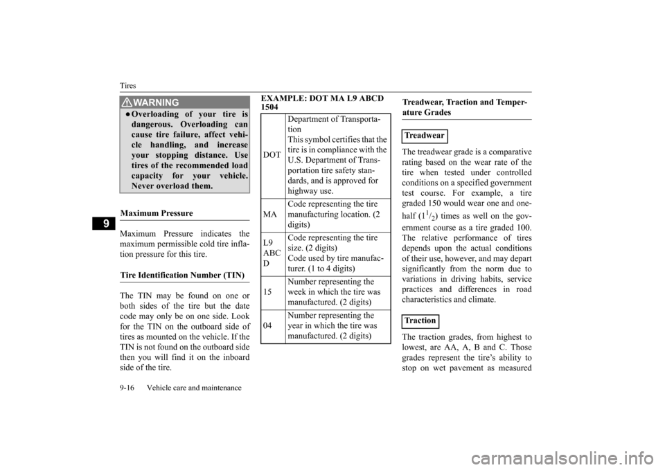
Maximum Pressure indicates the maximum permissible cold tire infla- tion pressure for this tire. The TIN may be found on one or both sides of the tire but the date code may only be on one side. Look for the TIN on the outboard side of tires as mounted on the vehicle. If the TIN is not found on the outboard sidethen you will find it on the inboard side of the tire.
EXAMPLE: DOT MA L9 ABCD 1504
The treadwear grade is a comparative rating based on the wear rate of the tire when tested under controlledconditions on a specified government test course. For example, a tire graded 150 would wear one and one- half (1
1/2) times as well on the gov-
ernment course as a tire graded 100. The relative performance of tiresdepends upon the actual conditions of their use, however, and may depart significantly from the norm due tovariations in driving habits, service practices and differences in road characteristics and climate. The traction grades, from highest to lowest, are AA, A, B and C. Thosegrades represent the tire’s ability to stop on wet pavement as measured
WA R N I N GOverloading of your tire isdangerous. Overloading can cause tire failure, affect vehi-cle handling, and increase your stopping distance. Use tires of the recommended loadcapacity for your vehicle. Never overload them.
Maximum Pressure Tire Identification Number (TIN)
DOT
Department of Transporta- tion This symbol certifies that the tire is in compliance with the U.S. Department of Trans- portation tire safety stan-dards, and is approved for highway use.
MA
Code representing the tire manufacturing location. (2 digits)
L9 ABC D
Code representing the tire size. (2 digits)Code used by tire manufac- turer. (1 to 4 digits)
15
Number representing the week in which the tire was manufactured. (2 digits)
04
Number representing the year in which the tire was manufactured. (2 digits)
Treadwear, Traction and Temper- ature Grades Treadwear Tr a c t i o n
BK0206700US.bo
ok 16 ページ 2014年3月25日 火曜日 午後4時42分
Page 340 of 384
Tires
Vehicle care and maintenance 9-17
9
under controlled conditions on speci- fied government test surfaces of asphalt and concrete. A tire marked C may have poor traction perfor- mance. The temperature grades are A (the highest), B and C, representing the tire’s resistance to the generation ofheat and its ability to dissipate heat when tested under controlled condi- tions on a specified indoor laboratorytest wheel. Sustained high tempera- ture can cause the material of the tire to degenerate and reduce tire life, andexcessive temperature can lead to sudden tire failure. The grade C cor- responds to a level of performancewhich all passenger car tires must meet under the Federal Motor Vehi- cle Safety Standard No. 109. Grades B and A represent higher levels of performance on the laboratory testwheel than the minimum required by law.
N00939301955
Proper tire inflation pressure is essential for the safe and satisfactory operation of yourvehicle. The wrong tire pressure will cause problems in three major areas: Safety Too little pressure increases flexing in thetire and can cause tire failure. Too muchpressure can cause a tire to lose its ability to cushion shock. Objects on the road and potholes could then cause tire damage thatmay result in tire failure. Economy The wrong tire pressure can cause unevenwear patterns in the tire tread. These abnormal wear patterns will reduce the tread life, and the tire will have to bereplaced sooner. Too little pressure also makes it harder for the tire to roll, and this uses up more fuel. Ride comfort and vehicle stability The superior riding experience built into your vehicle partly depends on the correcttire pressure. Too much pressure gives an uncomfortable and jarring ride. Too little pressure feels as if your vehicle is slow torespond. Unequal tire pressures can make steering your vehicle uneven and unpredictable.
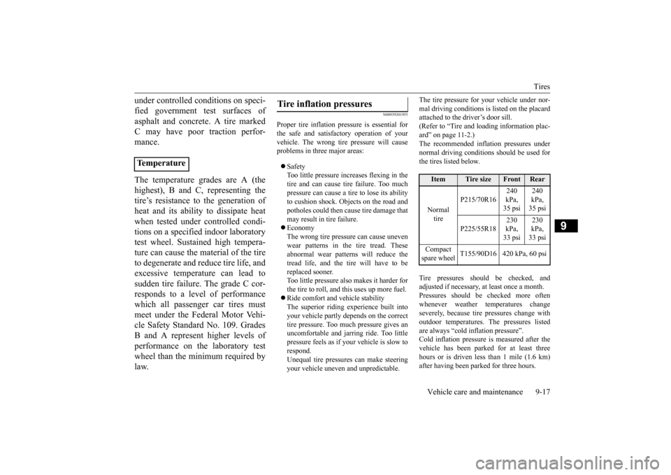
The tire pressure for your vehicle under nor- mal driving conditions is listed on the placard attached to the driver’s door sill. (Refer to “Tire and loading information plac-ard” on page 11-2.) The recommended infl
ation pressures under
normal driving conditions should be used forthe tires listed below. Tire pressures should be checked, and adjusted if necessary, at least once a month. Pressures should be checked more oftenwhenever weather temperatures change severely, because tire pressures change with outdoor temperatures. The pressures listedare always “cold inflation pressure”. Cold inflation pressure is measured after the vehicle has been parked for at least threehours or is driven less than 1 mile (1.6 km) after having been parked for three hours.
Temperature
Tire inflation pressures
Item
Tire size
Front
Rear
Normal tire
P215/70R16
240 kPa, 35 psi
240 kPa, 35 psi
P225/55R18
230 kPa, 33 psi
230 kPa, 33 psi
Compact spare wheel
T155/90D16 420 kPa, 60 psi
BK0206700US.bo
ok 17 ページ 2014年3月25日 火曜日 午後4時42分
Page 341 of 384
Tires 9-18 Vehicle care and maintenance
9
Cold inflation pressure must not go above the maximum values molded into the tire side- wall. After driving several miles, your tire inflation pressure may increase 2 to 6 psi (14to 41 kPa) from the cold inflation pressure. Do not let air out of the tires to get back to the specified cold pressure, or your tires will betoo low. Check your tires each time you refuel. If one tire looks lower than the others, check thepressure for all of them.You should also take the following safety pre- cautions: Keep your tires inflated to the recom- mended pressures. (See the tire and load-ing information placard attached to the driver’s door sill.) Stay within the recommended load limits. Make sure that the weight of any load in your vehicle is evenly distributed. Drive at safe speeds. After filling your tires to the correct pres- sure, check them for damage and air leaks. Be sure to reinstall the caps on thevalve stems.
N00939600241 N00939700141
The following maintenance steps are recom- mended:
Check tire pressures regularly. Have regular maintenance done on the wheel balance and front and rear suspen- sion alignment. Rotate your tires regularly as described in the “Tire rotation” section on page 9-19.
N00939800184
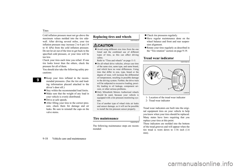
Tread wear indicators are built into the origi- nal equipment tires on your vehicle to helpyou know when your tires should be replaced. Many states have laws requiring that you replace your tires at this point.These indicators are molded into the bottom of the tread grooves and will appear when the tire tread is worn down to 1/16 inch (1.6mm).
Replacing tires and wheels
CAUTION Avoid using different
size tires from the one
listed and the combined use of different types of tires, as this can affect driving safety.Refer to “Tires and wheels” on page 11-5. On all-wheel drive vehicles, always use tires of the same size, same type, and same brand, and which have no wear differences. Using tires that differ in size, type, brand or thedegree of wear, will increase the differential oil temperature, resulting in possible damage to the driving system. Further, the drive trainwill be subjected to excessive loading, possi- bly leading to oil leakage, component sei- zure, or other serious problems. Only Mitsubishi Motors Authorized wheels should be used, because your vehicle isequipped with a tire pressure monitoring sys- tem. Use of another type of wheel risks air leaksand sensor damage, as it will not be possible to install the tire pressure sensor properly.
Tire maintenance
Tr e a d w e a r i n d i c a t o r 1- Location of the tread wear indicator 2- Tread wear indicator
BK0206700US.bo
ok 18 ページ 2014年3月25日 火曜日 午後4時42分