2015 MITSUBISHI OUTLANDER tire size
[x] Cancel search: tire sizePage 179 of 446

Adaptive Cruise Control System (ACC) (if so equipped) 5-102 Features and controls
5
N00581500027
There are two ways to increase the set speed. The set speed will increase by 1 mph (1 km/h) every time you push up the “RES +” switch while the ACC is activated. If youhold the switch pushed up, the set speed increases in 5 mph (5 km/h) increments.
When the accelerator
pedal is depressed
while driving with the ACC control working, you can accelerate the vehicle beyond thepresently set speed. When the vehicle spee
d reaches your desired
speed, push down and release the “SET -”
switch and release the accelerator pedal; the new speed is then set in the system.
CAUTION To maintain proper performance of the ACC:• Always clean the surface of the radar sen- sor.• Avoid impacting the radar sensor or its sur-rounding area.• Do not put a sticker on the radar sensor orits surrounding area.• Do not paint the radar sensor.• Do not install a grill guard.• Do not modify the radar sensor or its sur- rounding area.• Always use tires of the same size, sametype, and same brand, and which have no significant wear differences.• Do not modify the vehicle’s suspension.
To increase the set speed
By using the “RES +” switch:
NOTE
There is some time
lag until the vehicle
begins accelerating to
the new set speed after
the set speed has been changed. The set speed can be changed even while your vehicle is followi
ng a vehicle in front
using the ACC. In this case, however, although the set speed itself is increased,your vehicle will
not accelerate.
When the switch is he
ld, a buzzer will sound
every time the set speed changes
By using the accelerator pedal:
WA R N I N G The ACC braking control and approach alarm functions will
not work while the
accelerator pedal is depressed.NOTE
The set speed indicator in the multi informa- tion display will show
“---” while the accel-
erator pedal is depressed. If the “SET -” button is not pushed down while depressing the ac
celerator pedal, your
vehicle speed will return to the set speed, after the accelerator pedal is released. Whenthe accelerator pedal is released, the ACC braking control and approach alarm func- tions may not immediately work.
BK0211800US.book 102 ページ 2014年3月12日 水曜日 午後2時42分
Page 186 of 446
Forward Collision Mitigation System (FCM) (if so equipped)
Features and controls 5-109
5
N00577800032
This switch is used to turn on or off the FCM and also to select the distance which will trig-ger the forward collision warning function.
• When a vehicle ahea
d or an oncoming
vehicle is splashing wa
ter, snow or dirt.
When the system recognizes driver’s steering or accelerati
ng actions as evasive
actions to avoid collision, FCM controland alarm functions
may be canceled.
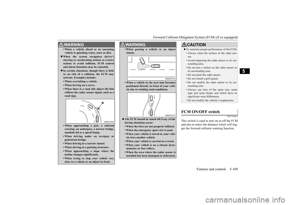
In certain situations,
though there is little
or no risk of a collision, the FCM may activate. Examples include: • When overtaking a vehicle.• When driving on a curve.• When there is a road
side object (B) that
reflects the radar sensor signal, such as aroad sign.• When approaching a gate, a railroadcrossing, an underpa
ss, a narrow bridge,
manhole lid or
a speed bump.
• When driving unde
r an overpass or
pedestrian bridge.• When driving in
a narrow tunnel.
• When driving in a parking structure.• When approaching a slope where the incline changes
significantly.
• When trying to stop your vehicle very close to a vehicle or
an object in front.
WA R N I N G
• When passing a vehicle or an object closely.• When a vehicle in the next lane becomespositioned directly in
front of your vehi-
cle due to winding road conditions.
The FCM should be tuned off if any of fol- lowing situations occur:• When the tires are not properly inflated. • When the emergency spare tire is used.• When your vehicle is
towed or your vehi-
cle tows another vehicle.• When your vehicle is carried on a truck.• When your vehicle is on a chassis dyna- mometer or free rollers.• When the area where the radar sensor isinstalled has been damaged or deformed.WA R N I N G
CAUTION To maintain proper performance of the FCM;• Always clean the surface of the radar sen- sor.• Avoid impacting the radar sensor or its sur-rounding area.• Do not put a sticker on the radar sensor orits surrounding area.• Do not paint the radar sensor.• Do not install a grill guard.• Do not modify the radar sensor or its sur- rounding area.• Always use tires of the same size, sametype and same brand,
and which have no
significant wear differences.• Do not modify the vehicle’s suspensions.
FCM ON/OFF switch
BK0211800US.book 109 ページ 2014年3月12日 水曜日 午後2時42分
Page 193 of 446
Tire pressure monitoring system 5-116 Features and controls
5
Each tire, including the spare (if provided), should be checked monthly when cold and inflated to the inflation pressure recom-mended by the vehicle manufacturer on the vehicle placard or tire in
flation pressure label.
(If your vehicle has tires of a different sizethan the size indicated on the vehicle placard or tire inflation pres
sure label, you should
determine the proper ti
re inflation pressure
for those tires.) As an added safety fe
ature, your vehicle has
been equipped with a ti
re pressure monitoring
system (TPMS) that illuminates a low tire pressure telltale when one or more of your tires is significan
tly under-inflated.
Accordingly, when the low tire pressure tell- tale illuminates, you should stop and check your tires as soon as
possible, and inflate
them to the proper pressure. Driving on a sig- nificantly under-inflated
tire causes the tire to
overheat and can lead to tire failure.
Under-inflation also reduces fuel efficiency and tire tread life, a
nd may affect the vehi-
cle’s handling and stopping ability. Please note that the TPMS is not a substitute for proper tire maintenance, and it is the driver’sresponsibility to mainta
in correct tire pres-
sure, even if under-inf
lation has not reached
the level to trigger illumination of the TPMSlow tire pressure telltale. Your vehicle has also been equipped with a TPMS malfunction indica
tor to indicate when
the system is not operating properly. The TPMS malfunction indicator is combined with the low tire pressure telltale.When the system detects a malfunction, the telltale will flash for approximately one min- ute and then remain continuously illuminated.This sequence will continue upon subsequent vehicle start-ups as
long as the malfunction
exists.When the malfunction indicator is illumi- nated, the system may not
be able to detect or
signal low tire pressure as intended.TPMS malfunctions may
occur for a variety
of reasons, including the installation of replacement or alternate tires or wheels on thevehicle that prevent the TPMS from function- ing properly. Always check the TPMS mal- function telltale after
replacing one or more
tires or wheels on your vehicle to ensure that the replacement or alternate tires and wheels
CAUTION If the tire pressure monitoring system warn- ing light does not illumi
nate when the igni-
tion switch is turned to the “ON” position orthe operation mode is put in ON, it means that the tire pressure monitoring system is not working properly. Have the systeminspected by an authorized Mitsubishi Motors dealer. In such situations,
a malfunctioning of the
system may be preventing the monitoring of the tire pressure. Avoid sudden braking, sharp turning and high-speed driving. If a malfunction is detected in the tire pres- sure monitoring system, the tire pressuremonitoring system warn
ing light will blink
for approximately 1 minute and then remain continuously illuminated. The warning lightwill issue further warnings each time the engine is restarted as
long as the malfunction
exists.Check to see whether
the warning light goes
off after few minutes driving. If it then goes off during driving, there is noproblem. However, if the warning light does not go off, or if it blinks again when the engine isrestarted, have the vehicle inspected by an authorized Mitsubishi Motors dealer. In such situations,
a malfunctioning of the
system may be preventing the monitoring of the tire pressure. For safety reasons, when the warning light appears while driving,avoid sudden braking, sharp turning and high-speed driving.
NOTE
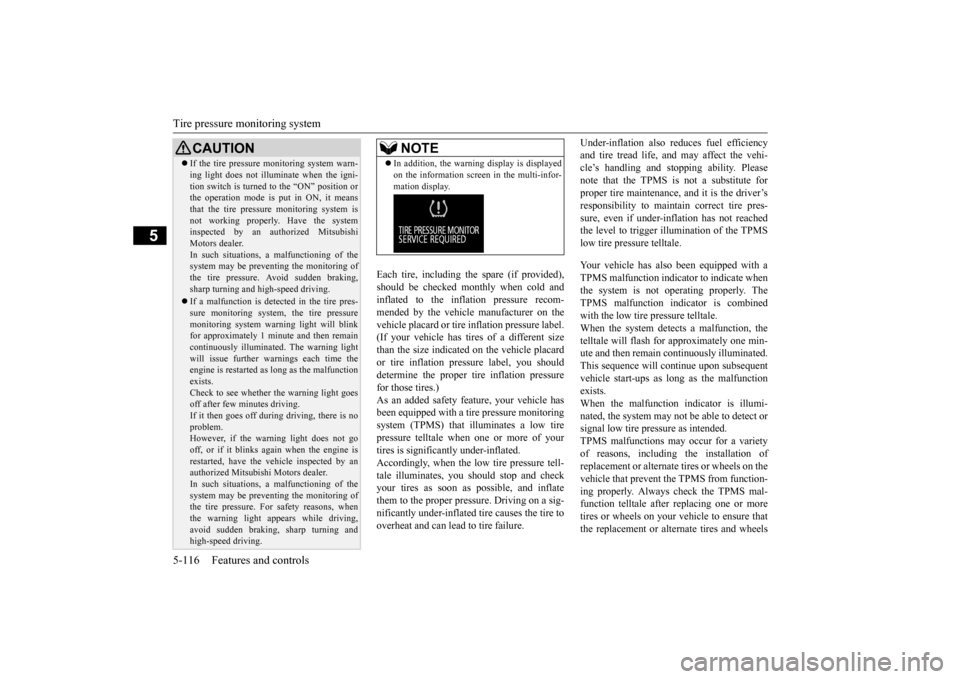
In addition, the warni
ng display is displayed
on the information screen in the multi-infor-mation display.
BK0211800US.book 116 ページ 2014年3月12日 水曜日 午後2時42分
Page 306 of 446

Loading information Driving safety 6-7
6
Vehicle maximum load on the tire: load on an individual tire that is determined bydistributing to each axle its share of the maximum loaded vehicle weight and dividing by two. Vehicle normal load on the tire: load on an individual tire that is determined by dis- tributing to each axle its share of the curbweight, accessory weight, and normal occupant weight and dividing by two. Maximum loaded vehicle weight: the sum of - (a) Curb weight;(b) Accessory weight; (c) Vehicle capacity weight; and (d) Production options weight. Curb weight: the weight of a motor vehi- cle with standard e
quipment including the
maximum capacity of fuel, oil, and cool-ant. Accessory weight: the combined weight (in excess of those
standard items which
may be replaced) of automatic transmis- sion, power steering, power brakes, power windows, power seats, radio, and heater,to the extent that these items are available as factory- installed equipment (whether installed or not). Vehicle capacity weight: the rated cargo and luggage load plus 150 lbs (68 kg) * times the vehicle’s
designated seating
capacity.
Production options weight: the combined weight of those installed regular produc-tion options weighing over 5 lbs (2.3 kg) in excess of those standard items which they replace, not prev
iously considered in
curb weight or accessory weight, includ- ing heavy duty brakes,
ride levelers, roof
rack, heavy duty battery, and special trim. Normal occupant weight: 150 lbs (68 kg) * times the number of
specified occupants
(3 in the case of your vehicle) Occupant distribution:
Occupant distribu-
tion within the passenger compartment (Inyour vehicle the distribution is 2 in front, 1 in second row seat)
N00630101407
The tire and loading information placard is located on the inside sill of the driver’s door.
This placard shows the maximum number of occupants permitted to
ride in your vehicle as
well as “the combined
weight of occupants
and cargo” (A), which
is called the vehicle
capacity weight. The weight of any non-fac-tory installed options, as well as the tongue weight of a trailer being towed and roof load is included in the defi
nition of “cargo” when
determining the vehicle
capacity weight. This
placard also tells you the size and recom- mended inflation pressure for the originalequipment tires on your vehicle. For more information, refer to
“Tires” on page 9-14.
* :150 lbs (68 kg) is th
e weight of one per-
son as defined by U.S.A. and Canadian regulations.
Tire and loading information placard
BK0211800US.book 7 ページ 2014年3月12日 水曜日 午後2時42分
Page 376 of 446
How to change a tire
For emergencies 8-11
8
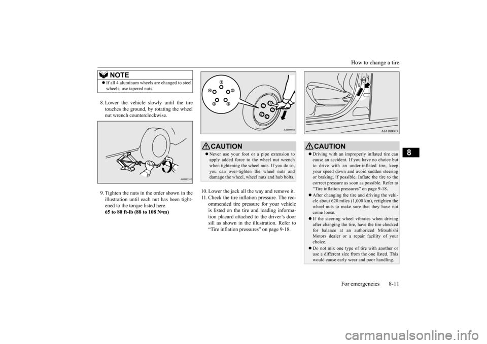
8. Lower the vehicle slowly until the tire touches the ground, by rotating the wheel nut wrench counterclockwise. 9. Tighten the nuts in the order shown in the illustration until each
nut has been tight-
ened to the torque listed here.65 to 80 ft-lb (88 to 108 N•m)
10. Lower the jack all the way and remove it. 11. Check the tire inflation pressure. The rec-
ommended tire pressure for your vehicleis listed on the tire
and loading informa-
tion placard attached to the driver’s door sill as shown in the illustration. Refer to“Tire inflation pressures” on page 9-18.
NOTE
If all 4 aluminum wheels are changed to steel wheels, use tapered nuts.
CAUTION Never use your foot or a pipe extension to apply added force to the wheel nut wrenchwhen tightening the wheel nuts. If you do so, you can over-tighten the wheel nuts and damage the wheel, wheel nuts and hub bolts.
CAUTION Driving with an imprope
rly inflated tire can
cause an accident. If
you have no choice but
to drive with an under-inflated tire, keep your speed down and avoid sudden steering or braking, if possible. Inflate the tire to thecorrect pressure as s
oon as possible. Refer to
“Tire inflation pressures” on page 9-18. After changing the tire
and driving the vehi-
cle about 620 miles (1,000 km), retighten the wheel nuts to make sure
that they have not
come loose. If the steering wheel vibrates when driving after changing the tire, have the tire checked for balance at an authorized Mitsubishi Motors dealer or a repair facility of yourchoice. Do not mix one type of tire with another or use a different size from the one listed. This would cause ea
rly wear and poor handling.
BK0211800US.book 11 ページ 2014年3月12日 水曜日 午後2時42分
Page 396 of 446
Tires
Vehicle care and maintenance 9-15
9
Recommended inflation pressure: the inflation pressure for optimum tire perfor-mance. Intended outboard sidewall: • The sidewall that c
ontains a whitewall,
bears white letteri
ng or bears manufac-
turer, brand, and/or model name molding that is higher or deeper than the samemolding on the other sidewall of the tire, or • The outward facing si
dewall of an asym-
metrical tire that has a particular side that must always face outward whenmounted on a vehicle.
Passenger car tire: a
tire intended for use
on passenger cars, multipurpose passen-ger vehicles, and trucks that have a gross vehicle weight rati
ng (GVWR) of 10,000
pounds or less. Light truck (LT) tire: a tire designated by its manufacturer as primarily intended for use on lightweight truc
ks or multipurpose
passenger vehicles. Tread: portion of a tire that comes into contact with the road. Tread rib: a tread se
ction running circum-
ferentially around a tire. Tread separation: pulling away of the tread from the tire carcass. Carcass: the tire structure, except tread and sidewall rubber which, when inflated,bears the load.
Sidewall: portion of a tire between the tread and bead. Section width: the line
ar distance between
the exteriors of the sidewalls of an inflated tire, excluding elevations due tolabeling, decoration, or protective bands. Bead: the part of the tire that is made of steel wires, wrapped
or reinforced by ply
cords and that is shaped to fit the rim. Ply: a layer of rubber-coated parallel cords. Cord: the strands forming the plies in the tire. Rim: a metal support for a tire or a tire and tube assembly upon which the tire beads are seated. Rim diameter: nominal diameter of the bead seat. Groove: the space between two adjacent tread ribs.
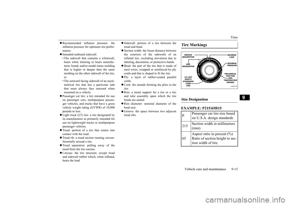
EXAMPLE: P215/65R15Tire Markings Size Designation P
Passenger car tire size based on U.S.A. design standards
215
Section width in millimeters (mm)
65
Aspect ratio in percent (%) Ratio of section height to sec- tion width of tire.
BK0211800US.book 15 ページ 2014年3月12日 水曜日 午後2時42分
Page 397 of 446

Tires 9-16 Vehicle care and maintenance
9
EXAMPLE: 95H
Maximum load indicates the maxi- mum load this tire is designed to carry.
R
Construction code •“R” means radial construc- tion. •“D” means diagonal or bias construction.
15 Rim diameter in inches (in)
NOTE
European/Japanese metric tire sizing is based on European/Jap- anese design standards. Tires designed to these standards havethe tire size molded into the sidewall beginning with the sec- tion width. The letter “P” isabsent from this tire size desig- nation. Example: 215/65R15 96H.
LT (Light Truck) -metric tiresizing is based on U.S.A. design standards. The size designation for LT-metric tires is the same asfor P-metric tires except for the letters “LT” that are molded into the sidewall preceding the sizedesignation. Example: LT235/85R16.Temporary spare tires are highpressure compact spares designed for temporary emer-gency use only. Tires designed to this standard have the letter “T” molded into the sidewallpreceding the si
ze designation.
Example: T145/80D18 103M.
Service Description 95
Load index A numerical code associated with the maximum load a tire can carry.NOTE
H
Speed symbol A symbol indicating the range of speeds at which a tire can carry a load corre- sponding to its load index under certain operating con- ditions. The maximum speed corre-sponding to the speed symbol should only be achieved under specified operating conditions. (i.e. tire pressure, vehicle loading, road condi- tions and posted speed limits)
Maximum Load
BK0211800US.book 16 ページ 2014年3月12日 水曜日 午後2時42分
Page 398 of 446
Tires
Vehicle care and maintenance 9-17
9
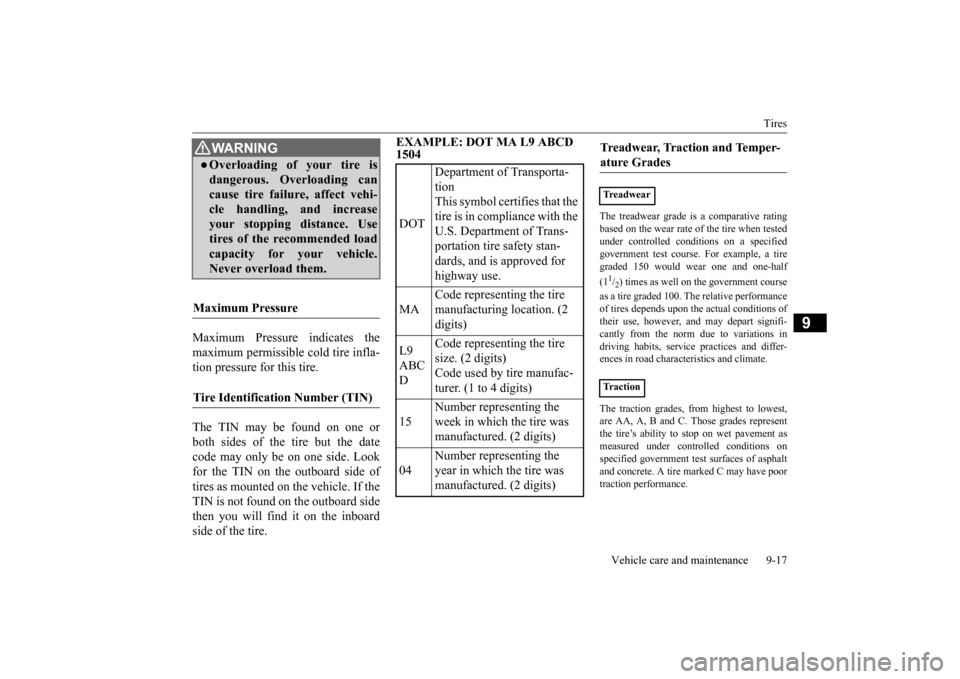
Maximum Pressure indicates the maximum permissible cold tire infla- tion pressure for this tire. The TIN may be found on one or both sides of the tire but the datecode may only be on one side. Look for the TIN on the outboard side of tires as mounted on the vehicle. If theTIN is not found on the outboard side then you will find it on the inboard side of the tire.
EXAMPLE: DOT MA L9 ABCD 1504
The treadwear grade is a comparative rating based on the wear rate of the tire when testedunder controlled conditions on a specified government test course. For example, a tire graded 150 would wear one and one-half (11/2) times as well on th
e government course
as a tire graded 100.
The relative performance
of tires depends upon th
e actual conditions of
their use, however, and may depart signifi-cantly from the norm due to variations in driving habits, service
practices and differ-
ences in road characteristics and climate. The traction grades, from highest to lowest, are AA, A, B and C. Those grades represent the tire’s ability to
stop on wet pavement as
measured under controlled conditions onspecified government te
st surfaces of asphalt
and concrete. A tire marked C may have poor traction performance.
WA R N I N GOverloading of your tire is dangerous. Overloading can cause tire failure, affect vehi- cle handling, and increaseyour stopping distance. Use tires of the recommended load capacity for your vehicle.Never overload them.
Maximum Pressure Tire Identification Number (TIN)
DOT
Department of Transporta- tion This symbol certifies that the tire is in compliance with the U.S. Department of Trans- portation tire safety stan- dards, and is approved for highway use.
MA
Code representing the tire manufacturing location. (2 digits)
L9 ABC D
Code representing the tire size. (2 digits) Code used by tire manufac-turer. (1 to 4 digits)
15
Number representing the week in which the tire was manufactured. (2 digits)
04
Number representing the year in which the tire was manufactured. (2 digits)
Treadwear, Traction and Temper-ature Grades Treadwear Traction
BK0211800US.book 17 ページ 2014年3月12日 水曜日 午後2時42分