Page 407 of 446
Fuses 9-26 Vehicle care and maintenance
9
*: Fusible link Some fuses may not be installed on your vehicle, depending on the vehicle modelor specifications. The table above shows the main equip- ment corresponding to each fuse.
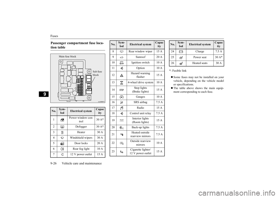
Passenger compartment fuse loca- tion table No.
Sym- bol
Electrical system
Capacity
1
Power window con-
trol
30 A*
2 Defogger 30 A* 3 Heater 30 A 4 Windshield wipers 30 A5 Door locks 20 A6 Rear fog light 10 A7 12 V power outlet 15 A
Sub fuse block
Main fuse block
8 Rear window wiper 15 A9 Sunroof 20 A 10 Ignition switch 10 A 11 Option 10 A 12
Hazard warning
flasher
15 A
13 4-wheel drive system 10 A 14
Stop lights (Brake lights)
15 A
15 Gauges 10 A 16 SRS airbag 7.5 A 17 Radio 15 A18 Control unit relay 7.5 A 19
Interior lights (Room lights)
15 A
20 Back-up lights 7.5 A 21
Heated outside rearview mirrors
7.5 A
22
Outside rearview
mirrors
10 A
23
Cigarette lighter/ 12 V power outlet
15 A
No.
Sym- bol
Electrical system
Capacity
24 Charge 7.5 A 25 Power seat 30 A*26 Heated seats 30 ANo.
Sym- bol
Electrical system
Capacity
BK0211800US.book 26 ページ 2014年3月12日 水曜日 午後2時42分
Page 408 of 446
Fuses
Vehicle care and maintenance 9-27
9
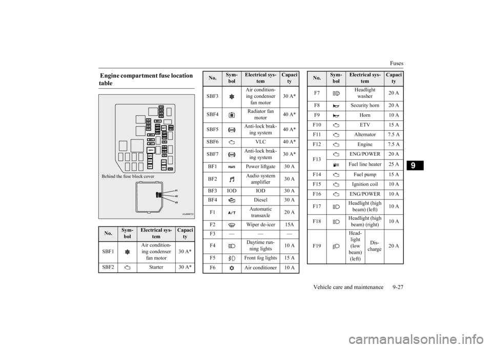
Engine compartment fuse location table No.
Sym- bol
Electrical sys-
tem
Capacity
SBF1
Air condition- ing condenser fan motor
30 A*
SBF2 Starter 30 A*Behind the fuse block cover
SBF3
Air condition- ing condenser fan motor
30 A*
SBF4
Radiator fan
motor
40 A*
SBF5
Anti-lock brak- ing system
40 A*
SBF6 VLC 40 A* SBF7
Anti-lock brak- ing system
30 A*
BF1 Power liftgate 30 A BF2
Audio system amplifier
30 A
BF3 IOD IOD 30 A BF4 Diesel 30 A F1
Automatic transaxle
20 A
F2 Wiper de-icer 15A F3 — — — F4
Daytime run- ning lights
10 A
F5 Front fog lights 15 A F6 Air conditioner 10 ANo.
Sym- bol
Electrical sys-
tem
Capacity
F7
Headlight washer
20 A
F8 Security horn 20 A F9 Horn 10 AF10 ETV 15 A F11 Alternator 7.5 A F12 Engine 7.5 A F13
ENG/POWER 20 A Fuel line heater 25 A
F14 Fuel pump 15 A F15 Ignition coil 10 A F16 ENG/POWER 10 A F17
Headlight (high beam) (left)
10 A
F18
Headlight (high beam) (right)
10 A
F19
Head- light (low beam) (left)
Dis- charge
20 A
No.
Sym- bol
Electrical sys-
tem
Capacity
BK0211800US.book 27 ページ 2014年3月12日 水曜日 午後2時42分
Page 409 of 446
Fuses 9-28 Vehicle care and maintenance
9
*: Fusible link Some fuses may not be installed on your vehicle, depending on the vehicle model or specifications. The table above shows the main equip- ment corresponding to each fuse.
The fuse block does not contain spare 7.5 A, 25 A or 30 A fuses. If one of these fusesburns out, substitute w
ith the following fuse.
7.5 A: 10 A spare fuse 25 A: 20 A spare fuse30 A: 30 A audio system amplifier fuse When using a substitute
fuse, replace with a
fuse of the correct capa
city as soon as possi-
ble.
N00954901141
1. Before replacing a fuse, always turn off the electrical item
connected to the fuse
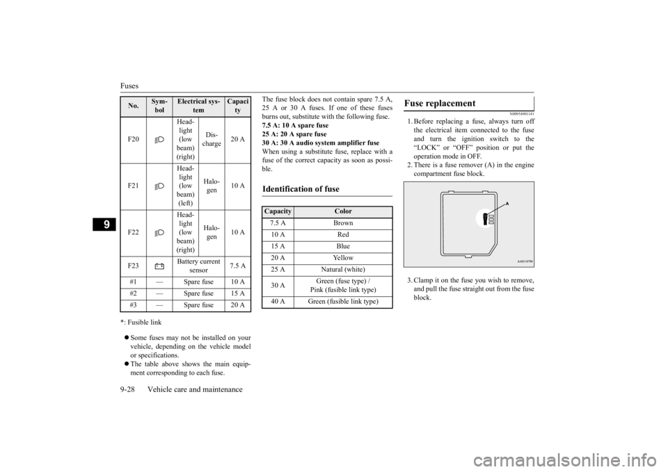
and turn the ignition switch to the“LOCK” or “OFF” position or put the operation mode in OFF. 2. There is a fuse remover (A) in the enginecompartment fuse block. 3. Clamp it on the fuse you wish to remove, and pull the fuse straight out from the fuseblock.
F20
Head- light (low beam) (right)
Dis- charge
20 A
F21
Head- light (low beam) (left)
Halo- gen
10 A
F22
Head- light (low beam) (right)
Halo- gen
10 A
F23
Battery current
sensor
7.5 A
#1 — Spare fuse 10 A #2 — Spare fuse 15 A #3 — Spare fuse 20 ANo.
Sym- bol
Electrical sys-
tem
Capacity
Identification of fuse Capacity
Color
7.5 A Brown 10 A Red 15 A Blue 20 A Yellow 25 A Natural (white) 30 A
Green (fuse type) / Pink (fusible link type)
40 A Green (fusible link type)
Fuse replacement
BK0211800US.book 28 ページ 2014年3月12日 水曜日 午後2時42分
Page 413 of 446
Replacement of light bulbs 9-32 Vehicle care and maintenance
9
N00950401656
N00901801131
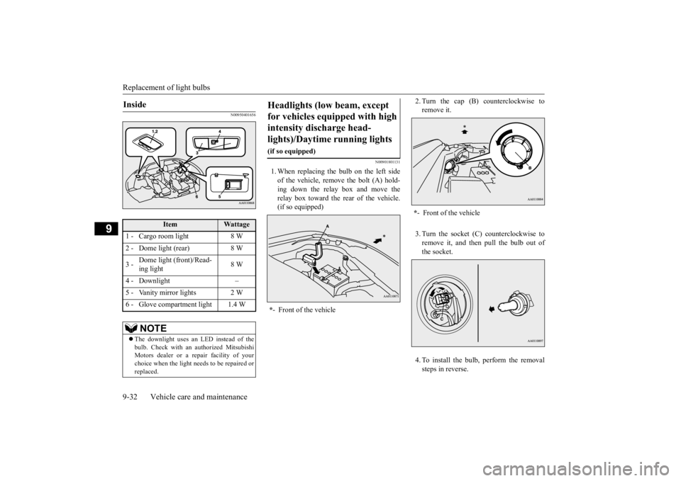
1. When replacing the bulb on the left side of the vehicle, remo
ve the bolt (A) hold-
ing down the relay box and move the relay box toward the rear of the vehicle. (if so equipped)
2. Turn the cap (B) counterclockwise to remove it. 3. Turn the socket (C) counterclockwise to remove it, and then pull the bulb out of the socket. 4. To install the bulb, perform the removal steps in reverse.
Inside
Item
Wattage
1 - Cargo room light 8 W 2 - Dome light (rear) 8 W 3 -
Dome light (front)/Read- ing light
8 W
4 - Downlight – 5 - Vanity mirror lights 2 W 6 - Glove compartment light 1.4 W
NOTE
The downlight uses an LED instead of the bulb. Check with an
authorized Mitsubishi
Motors dealer or a re
pair facility of your
choice when the light needs to be repaired or replaced.
Headlights (low beam, except for vehicles equipped with high intensity discharge head- lights)/Daytime running lights
(if so equipped) * - Front of the vehicle
*- Front of the vehicle
BK0211800US.book 32 ページ 2014年3月12日 水曜日 午後2時42分
Page 414 of 446
Replacement of light bulbs
Vehicle care and maintenance 9-33
9
N00900301139
Do not attempt to disass
emble or repair head-
lights, and do not attempt to replace their bulbs.
N00901901099
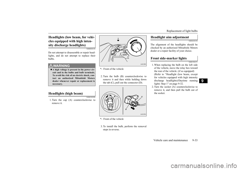
1. Turn the cap (A) counterclockwise toremove it.
2. Turn the bulb (B) counterclockwise to remove it and then while holding down the tab (C), pull out the connector (D). 3. To install the bulb, perform the removal steps in reverse.
N00943201359
The alignment of the headlights should be checked by an authorized Mitsubishi Motors dealer or a repair fa
cility of your choice.
N00915501171
1. When replacing the bulb on the left side of the vehicle, move the relay box toward the rear of the vehicle. (if so equipped) (Refer to “Headlight
(low beam, except
for vehicles equipped with high intensity discharge headlights)/Daytime running light): Step 1” on page 9-32.2. Turn the socket (A
) counterclockwise to
remove it, and then pull the bulb out of the socket.
Headlights (low beam, for vehi- cles equipped with high inten-sity discharge headlights)
WA R N I N G A high voltage is present in the power cir- cuit and in the bulbs and bulb terminals. To avoid the risk of an electric shock, con-tact an authorized
Mitsubishi Motors
dealer whenever repair or replacement is necessary.
Headlights (high beam)
* - Front of the vehicle * - Front of the vehicle
Headlight aim adjustment Front side-marker lights
BK0211800US.book 33 ページ 2014年3月12日 水曜日 午後2時42分
Page 415 of 446
Replacement of light bulbs 9-34 Vehicle care and maintenance
9
3. To install the bulb, perform the removal steps in reverse.
N00917301577
When replacing the bulb on the left side ofthe vehicle, move the relay box toward the rear of the vehicle. (if so equipped)
(Refer to “Headlight (low beam, except for vehicles equipped with
high intensity dis-
charge headlights)/Daytime running light): Step 1” on page 9-32.) 1. Turn the cap (A) counterclockwise to remove it. 2. Pull out the socket (B), and then pull the bulb out of the socket.
3. To install the bulb, perform the removal steps in reverse. 1. Turn the socket (A) counterclockwise to remove it, and then pull the bulb out ofthe socket.
* - Front of the vehicle
Parking lights
Except for vehicles equipped with high intensity discharge headlights *: Front of the vehicle
Vehicles equipped with high inten-sity discharge headlights
BK0211800US.book 34 ページ 2014年3月12日 水曜日 午後2時42分
Page 416 of 446
Replacement of light bulbs
Vehicle care and maintenance 9-35
9
2. To install the bulb, perform the removal steps in reverse.
N00943401380
1. Turn the socket (A
) counterclockwise to
remove it, then remove the bulb from thesocket by turning it counterclockwise while pressing in.
2. To install the bulb, perform the removal steps in reverse.
N00943501147
N00943601829
1. Insert a straight blade (or minus) screw- driver with a cloth over its tip at the edge of the cover (A) and pry gently to remove the cover.
*: Front of the vehicleFront turn signal lights
* : Front of the vehicleSide turn signal lights
(if so
equipped)
NOTE
The side turn signal lights uses an LED instead of the bulb. Check with an authorized Mitsubishi Motors dealer or a repair fa
cility of your choice
when the light needs to be repaired orreplaced.
Front fog lights (if so equipped)/Daytime running lights (if so equipped)
BK0211800US.book 35 ページ 2014年3月12日 水曜日 午後2時42分
Page 417 of 446
Replacement of light bulbs 9-36 Vehicle care and maintenance
9
2. Remove the 3 screws (B) and remove the light unit.
3. Turn the socket counterclockwise to remove it.
4. While holding down th
e tab (F), pull out
the bulb (G). 5. To install the bulb, perform the removal steps in reverse.
N00943701543
1. Open the liftgate.2. Remove the screws
(A), and then move
the light unit toward the rear of the vehi-cle to unfix the notch (B) and pins (C).
NOTE
When unfastening the screws or the fog light, be careful not to move the beam posi- tion adjustment screw (C).
D- Front fog light E- Daytime running lightType 1 Type 2 Type 3
Rear combination lights Front fog light Daytime running light
BK0211800US.book 36 ページ 2014年3月12日 水曜日 午後2時42分