2015 MITSUBISHI OUTLANDER III change wheel
[x] Cancel search: change wheelPage 154 of 446

S-AWC (Super-All Wheel Co
ntrol) (if so equipped)
Features and controls 5-77
5
N00576600020
While the drive mode is in the “4WD AUTO” position, if the ECO mode switch is switched ON, the drive mode will be changed to “4WDECO” mode. If the ECO mode switch is switched OFF, the drive mode will be returned to “4WD AUTO”mode. Refer to the “ECO
mode switch” on page
5-177.
N00541301059
S-AWC is an integr
ated vehicle dynamics
control system that helps enhance drivingperformance, cornering performance, and vehicle stability over a wide range of driving conditions through integr
ated management of
the electronically cont
rolled 4WD, the AYC
(Active Yaw Control), the ABS and the ASC. The electronically controlled 4WD is a sys- tem that improves acceleration performance and stability perform
ance by controlling
front-rear distribution of
driving torque with
operating the electronic control coupling arranged in the rear differential assembly. The AYC is a system, with a left-right differ- ential limiting function
and yaw control func-
tion, that controls the left-right driving/braking force by managing the AFD*(Active Front Differential), the brake, the EPS. *: AFD (Active Front Differential)The Differential assembly that limits the front left-right differential
speed by operating elec-
tronic control clutch arranged in the transferassembly.
CAUTION Make sure that all four tires are the same specified size, type, a
nd brand, and have no
significant difference
in the amount of wear.
Otherwise, the elec
tronically controlled
4WD system may not work properly, and the 4WD system warning (overheating or ser-vice required) may displayed.
When the ECO mode switch is ON
NOTE
If the drive mode is switched in any mode after the drive mode is switched in “4WD ECO”, the drive mode will not be changed even if the ECO mode switch is switchedOFF.
S-AWC (Super-All Wheel Control)
(if so equipped)
CAUTION Do not over-rely on the S-AWC. Even the S- AWC cannot prevent the natural laws of physics from acting on the vehicle. This sys-tem, like any other sy
stem, has limits and
cannot help you to main
tain traction and con-
trol of the vehicle in
all circumstances. Reck-
less driving can lead to
accidents. It is the
driver’s responsibility to drive carefully. This means taking into account the traffic,road and environmental conditions.
Electronically Controlled 4WD
NOTE
If the parking brake lever is pulled up while the vehicle is moving, the front-rear distribu- tion of driving torque control will turn OFF which will allow the rear wheels to lock eas-ier.
Active Yaw Control (AYC)
CAUTION Control of the braking force does not enhance the stopping performance of thevehicle, therefore, pa
y careful attention to
the safety of your surroundings when driv- ing.
BK0211800US.book 77 ページ 2014年3月12日 水曜日 午後2時42分
Page 155 of 446
S-AWC (Super-All Wheel Control) (if so equipped) 5-78 Features and controls
5
The left-right differen
tial limiting function is
a function that enhanc
es driving performance
and vehicle stability by preventing idle spin- ning of a wheel when driving on slipperyroad or when the road surfaces of left and right wheels are different. The yaw control function is a function that enhances vehicle corn
ering performance and
vehicle stability with
management of vehicle
turning power (yaw moment) by controlling the drive power difference of the left andright wheels and the braking force when the vehicle does not turn
in response to steering
input, such as when the steering wheel isturned quickly or when driving on slippery road.
N00542401073
Select the control mode from the followingfour types to suit the driving conditions.
4-wheel drive operation requires special driv- ing skills.Carefully read the “4-wheel drive operation” section on page 5-80 and take care to drive safety.
N00583000039
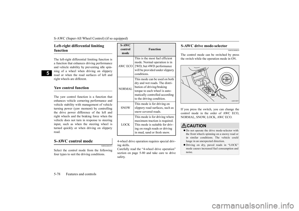
The control mode can
be switched by press
the switch while the operation mode in ON. If you press the switch, you can change the control mode in the order of AWC ECO,NORMAL, SNOW, LOCK, AWC ECO.
Left-right differential limiting function
Yaw control function
S-AWC control mode
S-AWC control mode
Function
AW C E C O
This is the most fuel efficient mode. Normal operation is in 2WD, but 4WD performance will be provided under slippery conditions.
NORMAL
This mode can be used on both dry and wet roads. The distri- bution of driving/braking torque to each wheel is auto-matically controlled according to the driving condition.
SNOW
This mode is for driving on slippery road surfaces, such as snow-covered roads.
LOCK
This mode is for driving where maximum traction is required. This mode is suitable for driv-ing on rough roads or driving in mud, sand or fresh snow.
S-AWC drive mode-selector
CAUTION Do not operate the dr
ive mode-selector with
the front wheels spinning on a snowy road or in similar conditions
. The vehicle could
lunge in an unexpected direction. Driving on dry, paved roads in “LOCK” mode causes increased fuel consumption andnoise.
BK0211800US.book 78 ページ 2014年3月12日 水曜日 午後2時42分
Page 156 of 446

S-AWC (Super-All Wheel Co
ntrol) (if so equipped)
Features and controls 5-79
5
N00583100027
The currently selected control mode is dis- played on the multi-
information display.
In addition, when the control mode ischanged, the selected mode appears on the interrupt display screen of the information screen in the multi-information display.The control mode displa
y will appear on the
information screen for a few seconds, and then the original screen will return.
Warning display Warning display
N00542501058
The S-AWC operation stat
us can be displayed
on the information screen in the multi-infor- mation display. To display the status, press the multi-informa-tion meter switch to change the information screen. Refer to “Information
screen (when the oper-
ation mode in ON)” on page 5-126. The S-AWC operation st
atus is displayed.
NOTE
The control mode can be switched while driving or stopped.
S-AWC control mode display
Example: “AWC ECO” mode is selected.
CAUTION If the selected drive
mode indicator begins
blinking, the drive m
ode will automatically
switch to protect the drive-system compo-nents. A warning will
also be displayed in
the information screen in the multi informa- tion display.Reduce speed and, if the indicator stops blinking, you may resume normal driving.CAUTION If the selected drive mode indicator (4WD) is blinking, a problem has occurred with theelectronically
controlled 4WD. A warning
will also be displayed in the information screen in the multi information display. Haveyour vehicle inspected
by an authorized Mit-
subishi Motors dealer.
CAUTION Make sure that all four tires are the same specified size, type, a
nd brand, and have no
significant difference in the amount of wearfor all 4 wheels. Otherwise, the S-AWC sys- tem may not work properly, and a 4WD sys- tem warning (overheating or servicerequired) may
be displayed.
S-AWC operation display
Display example
BK0211800US.book 79 ページ 2014年3月12日 水曜日 午後2時42分
Page 157 of 446
4-wheel drive operation 5-80 Features and controls
5
N00576700021
While the drive mode is in the “NORMAL” position, if the ECO mode switch is switchedON, the drive mode
will be changed to
“AWC ECO” mode. If the ECO mode switch is switched OFF, thedrive mode will be returned to “NORMAL” mode. Refer to the “ECO mode switch” on page 5-177.
N00530601179
Your vehicle has been
designed primarily for
use on pavement. But its unique 4 -wheel drive system allowsyou to occasionally travel on unpaved roads, to campgrounds, picnic
sites, and similar
locations.Not only does this ensure better handling on dry, paved roads but al
so permits better trac-
tion when driving on slippery, wet or snow- covered roads and when moving out of mud.But it is not suitable for heavy off road use or towing in rough conditions. It is particularly im
portant to note that 4-
wheel drive may not gi
ve sufficient hill
climbing ability and e
ngine braking on steep
slopes. You should try to avoid driving onsteep slopes. Also, you must exercise caution when driving on sand and mud and when driving through water because sufficient traction may not be available in certain circumstances.Please avoid driving the vehicle through areas where the tires may get stuck in deep sand or mud.
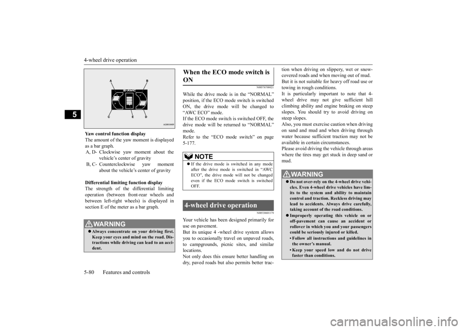
Yaw control function display The amount of the yaw moment is displayed as a bar graph. A, D- Clockwise yaw moment about the
vehicle’s center of gravity
B, C- Counterclockwise yaw moment
about the vehicle’s
center of gravity
Differential limiting
function display
The strength of the differential limitingoperation (between front-rear wheels and between left-right whee
ls) is displayed in
section E of the me
ter as a bar graph.
WA R N I N GAlways concentrate on
your driving first.
Keep your eyes and mi
nd on the road. Dis-
tractions while driving
can lead to an acci-
dent.
When the ECO mode switch is ON
NOTE
If the drive mode is switched in any mode after the drive mode is switched in “AWCECO”, the drive mode will not be changed even if the ECO mode switch is switched OFF.
4-wheel drive operation
WA R N I N G Do not over-rely on th
e 4-wheel drive vehi-
cles. Even 4-wheel drive vehicles have lim- its to the system and ability to maintaincontrol and traction.
Reckless driving may
lead to accidents. Al
ways drive carefully,
taking account of the road conditions. Improperly operating
this vehicle on or
off-pavement can cause an accident orrollover in which you
and your passengers
could be seriously
injured or killed.
• Follow all instructions and guidelines in the owner’s manual.• Keep your speed low and do not drivefaster than conditions.
BK0211800US.book 80 ページ 2014年3月12日 水曜日 午後2時42分
Page 158 of 446
4-wheel drive operation
Features and controls 5-81
5
When turning a sharp corner in “4WD LOCK” or “LOCK” position at low speed, a slight difference in
steering may be experi-
enced similar to feeling as if the brakes wereapplied. This is called tight corner braking and results from each of the four tires being at a different distance from the corner. The phe-nomenon is typical of 4-
wheel drive vehicles.
If this occurs, either straighten out the steer- ing wheel or change to another mode. Set the drive mode-selector to “4WD AUTO”, “4WD LOCK” or “SNOW” inaccordance with the road conditions, and then gradually depress the accelerator pedal for a smooth start.
Set the drive mode-selector to “4WD LOCK” or “LOCK” and then gradually depress theaccelerator pedal for a
smooth start. Keep the
pressure on the accelera
tor pedal as constant
as possible, and drive at low speed.
NOTE
Driving on rough roads can be hard on a vehicle. Before you le
ave the pavement, be
sure all scheduled ma
intenance and service
has been done, and that
you have inspected
your vehicle. Pay spec
ial attention to the
condition of the ti
res, and check the tire pres-
sures. Mitsubishi Motors is not responsible to the operator for any damage or injury caused or liability incurred by improper and negligent operation of a vehicl
e. All techniques of
vehicle operation depend on the skill and experience of the opera
tor and other partici-
pating parties. Any de
viation from the rec-
ommended operating instru
ctions above is at
their own risk. Note that the stopping distance required of the 4-wheel drive vehicle differs very little from that of the front-wheel drive vehicle.When driving on a snow-covered road or a slippery, muddy surface, make sure that you keep a sufficient dist
ance between your vehi-
cle and the one ahead of you. The driving posture s
hould be more upright;
adjust the seat to a good position for easy steering and pedal operati
on. Be sure to wear
the seat belt. After driving on rough roads, check each part of the vehicle
and wash it thoroughly
with water. Refer to the “Inspection and maintenance followi
ng rough road opera-
tion” section and “Vehicle care and Mainte-nance” sections.
CAUTION Setting the drive mode-selector to “4WD LOCK” or “LOCK” position to drive on drypaved road will increa
se fuel consumption,
with possible noise generation.
Turning sharp corners On snowy or icy roads
NOTE
The use of snow tires is recommended.
Maintain a safe distan
ce between
vehicles,
avoid sudden braking, and use engine brak-ing (downshifting).CAUTION Avoid sudden braking,
sudden acceleration
and sharp turning. Sk
idding occurs and con-
trol of the vehicle could be lost.
Driving on sandy or muddy roads
CAUTION Do not force the vehicle or drive recklessly on sandy surfaces. In comparison with nor- mal road surfaces, the engine and otherdrive-system components are put under excessive strain when driving on such a sur- face. This could lead to accidents. If any of the follow
ing conditions occur
while the vehicle is
being driven, immedi-
ately park your vehicle in a safe place and follow these procedures:NOTE
BK0211800US.book 81 ページ 2014年3月12日 水曜日 午後2時42分
Page 159 of 446
Inspection and maintenance following rough road operation 5-82 Features and controls
5
Your vehicle may not provide sufficient hill climbing ability and engine braking on steep slope. Avoid driving on steep slopes even though the vehicle is an 4-wheel drive vehi-cle.
N00537800085
If the electrical circuits become wet, furtheroperation of the vehicl
e will be impossible;
therefore, avoid drivi
ng through water unless
absolutely necessary. If driving through wateris unavoidable, use the following procedure: Check the depth of the water and the terrain before attempting to drive through it. Drive
slowly to avoid creating excessive water splashing.
N00530700085
After operating the vehicle in rough road con-ditions, be sure to perform the following inspection and maintenance procedures: Check that the vehicle has not been dam- aged by rocks, gravel, etc.
• If the engine coolan
t temperature display
flashes on the information screen in the multi-information di
splay or the engine
power drops suddenly. Refer to “Engine overh
eating” on page 8-4.
• If the “ ” warning display and “SLOW DOWN” or the “ ” wa
rning display and
“SERVICE REQUIRED” appear on the information screen in the multi-information display. Refer to “Warning disp
lay” on page 5-62,
5-69.WA R N I N G When attempting to rock your vehicle out of a stuck position, be sure that the area around the vehicle is clear of people and physical objects. The rocking motion maycause the vehicle to suddenly launch for- ward/backward, caus
ing injury or dam-
age to nearby people or objects.NOTE
Avoid sudden braking,
sudden ac
celeration
and sharp turning; such operations couldresult in the vehicle becoming stuck.CAUTION
If the vehicle become
s stuck in sandy or
muddy roads, it can often be moved with arocking motion. Move the selector leveralternately between the “D” (DRIVE) and “R” (REVERSE) positi
ons while pressing
lightly on the ac
celerator pedal.
Driving on rough road can cause rust on the vehicle; wash the vehi
cle thoroughly as soon
as possible after such use.
Climbing/descending sharp grades Driving through water
NOTE
CAUTION Never drive through water that is deep enough to cover wheel hubs, axles or exhaust pipe. Do not change th
e selector lever posi-
tion while driving through water.Frequent driving through water can adversely affect the life
span of the vehicle;
consult an authorized Mitsubishi Motorsdealer or a repair fac
ility of your choice and
take the necessary measures to prepare, inspect, and repair the vehicle. After driving through water, apply the brakes to be sure they are
functioning properly. If
the brakes are wet and not functioning prop- erly, dry them out by driving slowly while lightly depressing the brake pedal. Inspecteach part of the vehicle carefully.
Inspection and maintenance following rough road opera-tion
BK0211800US.book 82 ページ 2014年3月12日 水曜日 午後2時42分
Page 195 of 446
Rear-view camera (if so equipped) 5-118 Features and controls
5
A window tint that affects the radio wave signals is installed.
N00532900081
If new wheels with new tire inflation pressure sensors are installed, their ID codes must be programmed into the tire pressure monitoringsystem. Have tire and wheel replacement per- formed by an authorized Mitsubishi Motors dealer to avoid the ri
sk of damaging the tire
inflation pressure sensors. If the wheel replacement is not done by an authorized Mitsubishi Motors dealer
, it is not covered by
your warranty.
N00533001233
Your tire pressure monitoring system oper-ates on a radio frequency subject to Federal Communications Comm
ission (FCC) Rules
(For vehicles sold in U.S.A.) and IndustryCanada Rules (For vehicles sold in Canada). This device complies with part 15 of FCC Rules and Industry Ca
nada licence-exempt
RSS standard(s). Operation is subject to the following two con- ditions. This device may not
cause harmful inter-
ference. This device must ac
cept any interference
received, including interference that maycause undesired operation.
N00546201196
When the selector lever is in the “R”(REVERSE) position with the ignition switchin the “ON” position,
or the operation mode
is put in ON, the rear-view image will be dis- played on the screen of the Mitsubishi Multi-Communication System or the DISPLAY AUDIO. When the selector lever is shifted out of the “R” (REVERSE) position, the rear-view image will go off.
NOTE
Tire inflation pressures vary with the ambi- ent temperature. If the
vehicle is subjected to
large variations in am
bient temperature, the
tire inflation pressures may be under-inflated(causing the warning li
ght / display come on)
when the ambient temperature is relatively low. If the warning light / display comes on,adjust the tire inflation pressure.
Whenever the tires and wheels are replaced with new ones
CAUTION The use of non-genuine wheels will prevent the proper fit of the tire inflation pressuresensors, resulting air
leakage or damage of
the sensors.
General information
CAUTION Changes or modifica
tions not expressly
approved by the manufacturer for compli-ance could void the user’s authority to oper- ate the equipment.
Rear-view camera
(if so
equipped)
WA R N I N G Never rely solely on the rear-view camera to clear the area behind your vehicle. Always check visua
lly behind and all
around your vehicle fo
r persons, animals,
obstructions or other vehicles. Failure to do so can result in
vehicle damage, serious
injury or death. The rear-view camera is an aid system for backing up, but it is not a substitute for your visual confirmation. The view on the scre
en is limited, and
objects outside the view, such as under the bumper or around either corner of thebumper end, cannot be seen on the screen.
BK0211800US.book 118 ページ 2014年3月12日 水曜日 午後2時42分
Page 253 of 446
Headlight leveling swit
ch (if so equipped)
5-176 Features and controls
5
N00537101115
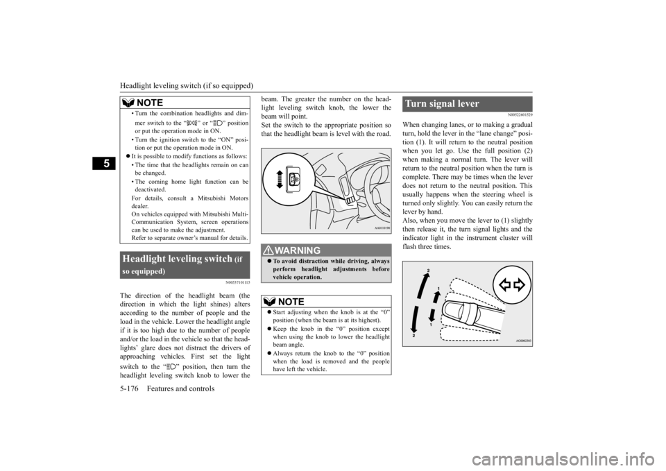
The direction of the headlight beam (the direction in which the light shines) altersaccording to the number of people and the load in the vehicle. Lo
wer the headlight angle
if it is too high due to the number of peopleand/or the load in the vehicle so that the head- lights’ glare does not distract the drivers of approaching vehicles. First set the light switch to the “ ” position, then turn the headlight leveling switch knob to lower the
beam. The greater the number on the head- light leveling switch knob, the lower thebeam will point. Set the switch to the appropriate position so that the headlight beam is level with the road.
N00522601529
When changing lanes, or to making a gradual turn, hold the lever in the “lane change” posi- tion (1). It will return
to the neutral position
when you let go. Use the full position (2) when making a normal turn. The lever will return to the neutral position when the turn iscomplete. There may be times when the lever does not return to the neutral position. This usually happens when the steering wheel is turned only slightly. You can easily return the lever by hand.Also, when you move the lever to (1) slightly then release it, the turn signal lights and the indicator light in the instrument cluster willflash three times.
• Turn the combination headlights and dim- mer switch to the “ ” or “ ” position or put the operation mode in ON. • Turn the ignition switch to the “ON” posi- tion or put the operation mode in ON.
It is possible to modify functions as follows: • The time that the he
adlights remain on can
be changed. • The coming home light function can be deactivated. For details, consult a Mitsubishi Motors dealer. On vehicles e
quipped with Mitsubishi Multi-
Communication System, screen operations can be used to ma
ke the adjustment.
Refer to separate owne
r’s manual for details.
Headlight leveling switch
(if
so equipped)
NOTE
WA R N I N G To avoid distraction while driving, always perform headlight
adjustments before
vehicle operation.NOTE
Start adjusting when the knob is at the “0” position (when the beam
is at its highest).
Keep the knob in the “0” position except when using the knob to lower the headlightbeam angle. Always return the knob to the “0” position when the load is removed and the people have left
the vehicle.
Turn signal lever
BK0211800US.book 176 ページ 2014年3月12日 水曜日 午後2時42分