2015 MINI Hardtop 2 Door tire pressure
[x] Cancel search: tire pressurePage 187 of 244

Repairing a flat tireSafety measures in case of a breakdown
Park the vehicle as far away as possible
from passing traffic and on solid ground.
Switch on the hazard warning system.
Turn the steering wheel until the front wheels
are in the straight-ahead position and engage
the steering wheel lock.
Secure the vehicle against rolling away by set‐
ting the parking brake.
Have all vehicle occupants get out of the vehi‐
cle and ensure that they remain outside the im‐
mediate area in a safe place, such as behind a
guardrail.
If necessary, set up a warning triangle at an ap‐
propriate distance.
Comply with all safety guidelines and regula‐
tions. ◀
Mobility System
The concept
With the Mobility System, minor tire damage
can be sealed quickly to enable continued
travel. To accomplish this, sealant is pumped
into the tires, which seals the damage from the
inside.
The compressor can be used to check the tire
inflation pressure.
Hints▷Follow the instructions on using the Mobi‐
lity System found on the compressor and
sealant container.▷Use of the Mobility System may be ineffec‐
tive if the tire puncture measures approx.
1/8 in/4 mm or more.▷Contact the nearest service center if the tire
cannot be made drivable.▷If possible, do not remove foreign bodies
that have penetrated the tire.▷Pull the speed limit sticker off the sealant
container and apply it to the steering
wheel.▷The use of a sealant can damage the TPM
wheel electronics. In this case, have the
electronics checked at the next opportunity
and have them replaced if needed.
Enclosed areas
Do not let the engine run in enclosed
areas, since breathing in exhaust fumes may
lead to loss of consciousness and death. The
exhaust gases contain carbon monoxide, an
odorless and colorless but highly toxic gas. ◀
Storage The Mobility System is located under the cargo
floor panel.
Sealant container
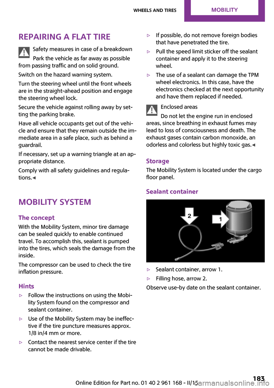
▷Sealant container, arrow 1.▷Filling hose, arrow 2.
Observe use-by date on the sealant container.
Seite 183Wheels and tiresMOBILITY183
Online Edition for Part no. 01 40 2 961 168 - II/15
Page 188 of 244

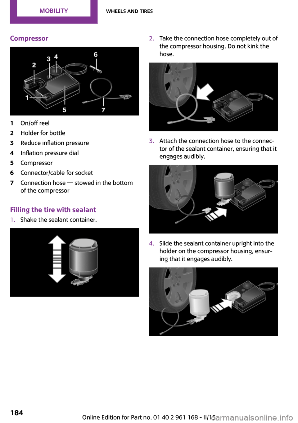
Compressor1On/off reel2Holder for bottle3Reduce inflation pressure4Inflation pressure dial5Compressor6Connector/cable for socket7Connection hose — stowed in the bottom
of the compressor
Filling the tire with sealant
1.Shake the sealant container.2.Take the connection hose completely out of
the compressor housing. Do not kink the
hose.3.Attach the connection hose to the connec‐
tor of the sealant container, ensuring that it
engages audibly.4.Slide the sealant container upright into the
holder on the compressor housing, ensur‐
ing that it engages audibly.Seite 184MOBILITYWheels and tires184
Online Edition for Part no. 01 40 2 961 168 - II/15
Page 189 of 244

5.Screw the connection hose onto the tire
valve of the defective wheel.6.With the compressor switched off, insert
the plug into a power socket inside the ve‐
hicle.7.With the ignition turned on or the engine
running, switch on the compressor.
Let the compressor run for approx. 3 to 8 mi‐
nutes to fill the tire with sealant and achieve a
tire inflation pressure of approx. 2.5 bar.
While the tire is being filled with sealant, the
tire inflation pressure may sporadically reach
approx. 5 bar. Do not switch off the compressor
at this point.
Switch off the compressor after 10 mi‐
nutes
Do not allow the compressor to run longer than
10 minutes; otherwise, the device will overheat
and may be damaged. ◀
If a tire inflation pressure of 2 bar is not
reached:1.Switch off the compressor.2.Unscrew the filling hose from the wheel.3.Drive forward and back to distribute the
sealant in the tire.4.Inflate the tire again using the compressor.
If a tire inflation pressure of 2 bar cannot be
reached, contact your service center.
Stowing the Mobility System
1.Remove the connection hose of the sealant
container from the wheel.2.Remove the connection hose from the seal‐
ant container.3.Wrap the empty sealant container and con‐
nection hose in suitable material to avoid
dirtying the cargo area.4.Stow the Mobility System back in the vehi‐
cle.
Distributing the sealant
Immediately drive approx. 5 mls/10 km/h to
ensure that the sealant is evenly distributed in the tire.
Do not exceed a speed of 50 mph/80 km/h.
If possible, do not drive at speeds less than
12 mph/20 km/h.
Seite 185Wheels and tiresMOBILITY185
Online Edition for Part no. 01 40 2 961 168 - II/15
Page 190 of 244

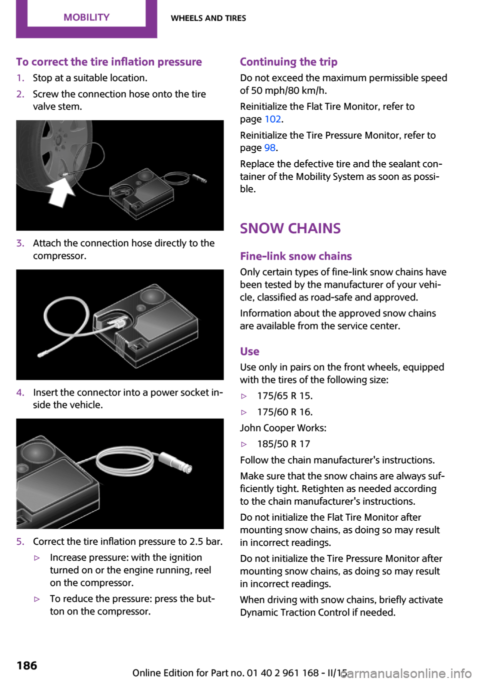
To correct the tire inflation pressure1.Stop at a suitable location.2.Screw the connection hose onto the tire
valve stem.3.Attach the connection hose directly to the
compressor.4.Insert the connector into a power socket in‐
side the vehicle.5.Correct the tire inflation pressure to 2.5 bar.▷Increase pressure: with the ignition
turned on or the engine running, reel
on the compressor.▷To reduce the pressure: press the but‐
ton on the compressor.Continuing the trip
Do not exceed the maximum permissible speed
of 50 mph/80 km/h.
Reinitialize the Flat Tire Monitor, refer to
page 102.
Reinitialize the Tire Pressure Monitor, refer to
page 98.
Replace the defective tire and the sealant con‐
tainer of the Mobility System as soon as possi‐
ble.
Snow chains Fine-link snow chains
Only certain types of fine-link snow chains have
been tested by the manufacturer of your vehi‐
cle, classified as road-safe and approved.
Information about the approved snow chains
are available from the service center.
Use Use only in pairs on the front wheels, equipped
with the tires of the following size:▷175/65 R 15.▷175/60 R 16.
John Cooper Works:
▷185/50 R 17
Follow the chain manufacturer's instructions.
Make sure that the snow chains are always suf‐
ficiently tight. Retighten as needed according
to the chain manufacturer's instructions.
Do not initialize the Flat Tire Monitor after
mounting snow chains, as doing so may result
in incorrect readings.
Do not initialize the Tire Pressure Monitor after
mounting snow chains, as doing so may result
in incorrect readings.
When driving with snow chains, briefly activate
Dynamic Traction Control if needed.
Seite 186MOBILITYWheels and tires186
Online Edition for Part no. 01 40 2 961 168 - II/15
Page 208 of 244

The wire is long enough to guide the socket
down and through between any heat shield
that may be installed and the bumper.4.Replace defective bulb.5.To install the new bulb, proceed in reverse
order of removal.
Right fog lamp:
1.Turn the bulb socket counterclockwise and
remove.
The wire is long enough to guide the socket
down and through between any heat shield
that may be installed and the bumper.2.Replace defective bulb.3.To install the new bulb, proceed in reverse
order of removal.
Side turn signal, bulb replacement
Follow the general instructions on lights and
bulbs, refer to page 198.
Bulbs:
▷With orange lens: W5W▷With white lens: WY5W diadem1.Pull the turn signal housing at the top out
of the catch, then unhook it at the bottom.2.Turn the bulb socket counterclockwise and
remove.3.Replace the bulb.4.Proceed in the reverse order to insert the
new bulb and install the turn signal hous‐
ing.
First hook the turn signal housing to the
bottom, then at the top press it into the
latch.
Changing wheels
Hints
When using run-flat tires or tire sealants, a tire
does not need to be changed immediately in
the event of pressure loss due to a flat tire.
Which is why no spare tire is available.
The tools for changing wheels are available as
accessories from your service center.
Seite 204MOBILITYReplacing components204
Online Edition for Part no. 01 40 2 961 168 - II/15
Page 211 of 244

The defective wheel cannot be stored in the
emergency wheel bracket because of its
size.3.Check tire inflation pressure at the next op‐
portunity and correct as needed.4.Reinitialize the Flat Tire Monitor, refer to
page 102.
Reinitialize the Tire Pressure Monitor, refer
to page 99.5.Replace the damaged tires as soon as pos‐
sible.
Driving with emergency wheel
Watch the speed when driving with the
emergency wheel
Drive conservatively and do not exceed a speed
of 50 mph/80 km/h; otherwise, changed driving
characteristics such as reduced lane stability
while braking, extended braking distance and
changed self-steering properties in the limit
area. ◀
Mount one emergency wheel only
Only a single emergency wheel may be
mounted. Reinstall wheels and tires of the orig‐
inal size as quickly as possible; otherwise, there
is a safety risk. ◀
Vehicle battery
Maintenance
The battery is maintenance-free, i.e., the elec‐
trolyte will last for the life of the battery.
Your service center will be glad to advise you
on questions regarding the battery.
Battery replacement Use approved vehicle batteries only
Only use vehicle batteries that have been
approved for your vehicle by the manufacturer;
otherwise, the vehicle could be damaged and
systems or functions may not be fully availa‐
ble. ◀
After a battery replacement, have the battery
registered on the vehicle by your service center
to ensure that all comfort features are fully
available and that any Check Control messages
are no longer displayed.
Charging the battery
General information Make sure that the battery is always sufficiently
charged to guarantee that the battery remains
usable for its full service life.
The battery may need to be charged in the fol‐
lowing cases:▷When making frequent short-distance
drives.▷If the vehicle is not used for prolonged peri‐
ods, longer than a month.▷Steptronic transmission: when parked for
long periods of time in selector lever posi‐
tion D, R or N.
Note
Do not connect charging devices to the
12 volt socket in the vehicle
Do not connect battery chargers to the factory-
installed 12 volt sockets in the vehicle as this
may damage the vehicle battery due to an in‐ creased power consumption. ◀
Starting aid terminals In the vehicle, only charge the battery via the
starting aid terminals, refer to page 210, in the
engine compartment with the engine off.
Power failure
After a temporary power loss, some equipment
needs to be reset.
Individual settings need to be reprogrammed:
▷Time: update.Seite 207Replacing componentsMOBILITY207
Online Edition for Part no. 01 40 2 961 168 - II/15
Page 218 of 244

CareVehicle features and op‐tions
This chapter describes all standard, country-
specific and optional features offered with the series. It also describes features that are not
necessarily available in your car, e. g., due to
the selected options or country versions. This
also applies to safety-related functions and sys‐
tems. The respectively applicable country provi‐
sions must be observed when using the respec‐
tive features and systems.
Car washes
General information Regularly remove foreign objects such as leaves
in the area below the windshield when the
hood is raised.
Wash your vehicle frequently, particularly in
winter. Intense soiling and road salt can dam‐
age the vehicle.
Hints Steam jets or high-pressure washers
When using steam jets or high-pressure
washers, hold them a sufficient distance away
and use a maximum temperature of
140 ℉/60 ℃.
If the vehicle has a glass sunroof, ensure that a
distance of at least 31.5 inches/80 cm is main‐
tained. Holding them too close or using exces‐
sively high pressures or temperatures can
cause damage or preliminary damage that may
then lead to long-term damage.
Follow the user's manual for the high-pressure
washer. ◀Cleaning sensors/camera lenses with
high-pressure washers
When using high-pressure washers, do not
spray the sensors and camera lenses on the
outside of the vehicle for long periods and
maintain a distance of at least 12 in/30 cm. ◀
Automatic car washes
Hints▷Give preference to cloth car washes or
those that use soft brushes in order to
avoid paint damage.▷Make sure that the wheels and tires are not
damaged by the transport mechanisms.▷Fold in the exterior mirrors; otherwise, they
may be damaged, depending on the width
of the vehicle.▷Unscrew the rod antenna.▷Deactivate the rain sensor, refer to
page 66, to avoid unintentional wiper acti‐
vation.▷In some cases, an unintentional alarm can
be triggered by the interior motion sensor
of the alarm system. Follow the instructions
on avoiding an unintentional alarm, refer to
page 44.
Guide rails in car washes
Avoid car washes with guide rails higher
than 4 in/10 cm; otherwise, the vehicle body
could be damaged. ◀
Before driving into a car wash In order to ensure that the vehicle can roll in a
car wash, take the following steps:
Manual transmission:
1.Drive into the car wash.2.Shift to neutral.Seite 214MOBILITYCare214
Online Edition for Part no. 01 40 2 961 168 - II/15
Page 234 of 244

Everything from A to ZIndexA
ABS, Antilock Brake Sys‐ tem 111
ACC, Active Cruise Control 115
Acceleration Assistant, refer to Launch Control 71
Activated-charcoal filter 137
Active Cruise Control, ACC 115
Additives, oil 191
Adjustments, seats/head re‐ straints 48
Adjustments, steering wheel 55
After washing vehicle 215
Airbags 95
Airbags, indicator/warning light 96
Air circulation, refer to Recir‐ culated-air mode 133, 137
Air conditioner 132
Air, dehumidifying, refer to Cooling function 133, 136
Air distribution, manual 133, 136
Air flow, air conditioner 133
Air flow, automatic climate control 136
Air pressure, tires 174
Air vents, refer to Ventila‐ tion 138
Alarm system 43
Alarm triggering 43
Alarm, unintentional 44
All around the center con‐ sole 16
All around the roofliner 17
All around the steering wheel 14
All-season tires, refer to Win‐ ter tires 182 Alternating-code hand-held
transmitter 140
Alternative oil types 192
Antifreeze, washer fluid 67
Antilock Brake System, ABS 111
Anti-slip control, refer to DSC 111
Approved axle load 221
Approved engine oils, see Suitable engine oil
types 192
Arrival time 82
Ash tray 143
Assistance when driving off 114
Assist system, refer to Intelli‐ gent Safety 103
AUTO intensity 136
Automatic car wash 214
Automatic climate con‐ trol 135
Automatic Curb Monitor 54
Automatic deactivation, front- seat passenger airbags 97
Automatic headlight con‐ trol 91
Automatic locking 43
Automatic recirculated-air control 137
Automatic transmission with Steptronic 68
AUTO program, automatic cli‐ mate control 136
AUTO program, intensity 136
Auto Start/Stop function 62
Average fuel consumption 82
Average speed 82
Axle loads, weights 221 B
Backrest curvature, refer to Lumbar support 49
Band-aids, refer to First aid kit 209
Bar for tow-starting/ towing 212
Battery replacement, vehicle battery 207
Battery, vehicle 207
Belts, safety belts 50
Beverage holder, cu‐ pholder 148
Bonus range, GREEN mode 164
Bottle holder, refer to Cu‐ pholder 148
Brake assistant 111
Brake discs, break-in 154
Brake pads, break-in 154
Braking, hints 155
Breakdown assistance 209
Break-in 154
Brightness of Control Dis‐ play 85
Bug light 199
Bulb replacement 198
Bulb replacement, front 199
Bulb replacement, rear 201
Bulb replacement, side 204
Bulbs and lights 198
Button, RES 117
Button, Start/Stop 60
Bypassing, refer to Jump- starting 209
C
California Proposition 65 Warning 8 Seite 230REFERENCEEverything from A to Z230
Online Edition for Part no. 01 40 2 961 168 - II/15