2015 MINI COUPE ROADSTER CONVERTIBLE coolant level
[x] Cancel search: coolant levelPage 69 of 231

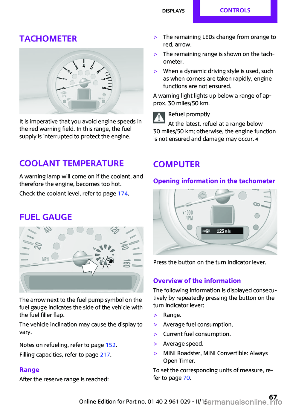
Tachometer
It is imperative that you avoid engine speeds in
the red warning field. In this range, the fuel
supply is interrupted to protect the engine.
Coolant temperature A warning lamp will come on if the coolant, and
therefore the engine, becomes too hot.
Check the coolant level, refer to page 174.
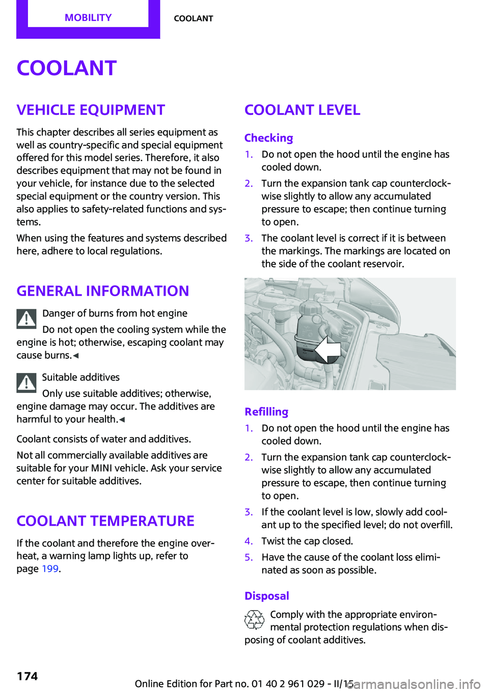
Fuel gauge
The arrow next to the fuel pump symbol on the
fuel gauge indicates the side of the vehicle with
the fuel filler flap.
The vehicle inclination may cause the display to
vary.
Notes on refueling, refer to page 152.
Filling capacities, refer to page 217.
Range After the reserve range is reached:
▷The remaining LEDs change from orange to
red, arrow.▷The remaining range is shown on the tach‐
ometer.▷When a dynamic driving style is used, such
as when corners are taken rapidly, engine
functions are not ensured.
A warning light lights up below a range of ap‐
prox. 30 miles/50 km.
Refuel promptly
At the latest, refuel at a range below
30 miles/50 km; otherwise, the engine function
is not ensured and damage may occur. ◀
Computer
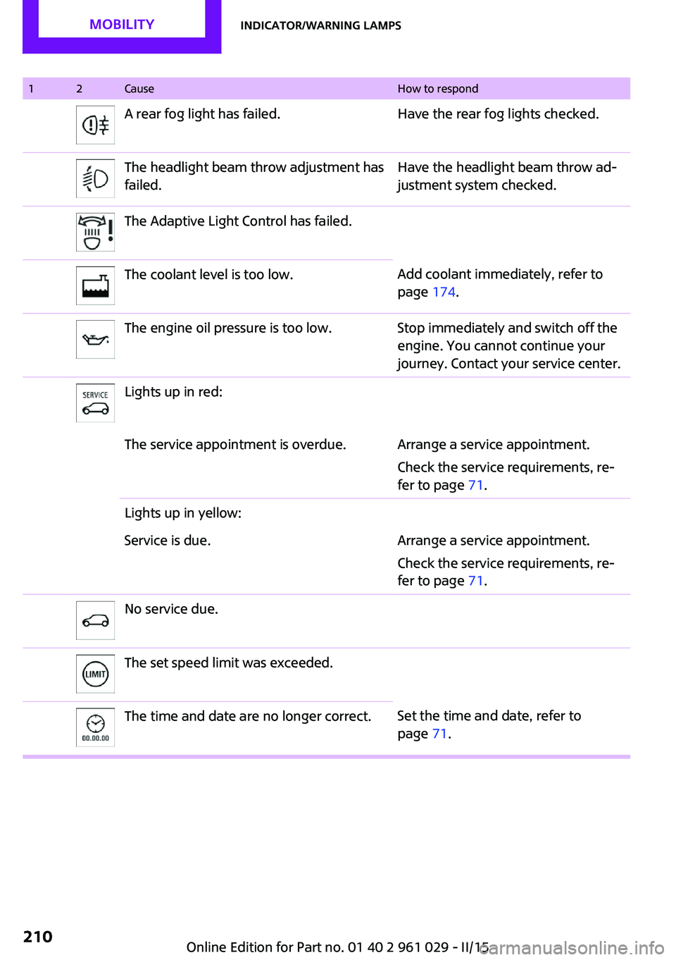
Opening information in the tachometer
Press the button on the turn indicator lever.
Overview of the information
The following information is displayed consecu‐
tively by repeatedly pressing the button on the
turn indicator lever:
▷Range.▷Average fuel consumption.▷Current fuel consumption.▷Average speed.▷MINI Roadster, MINI Convertible: Always
Open Timer.
To set the corresponding units of measure, re‐
fer to page 70.
Seite 67DisplaysCONTROLS67
Online Edition for Part no. 01 40 2 961 029 - II/15
Page 176 of 231

CoolantVehicle equipment
This chapter describes all series equipment as
well as country-specific and special equipment
offered for this model series. Therefore, it also
describes equipment that may not be found in
your vehicle, for instance due to the selected
special equipment or the country version. This
also applies to safety-related functions and sys‐
tems.
When using the features and systems described
here, adhere to local regulations.
General information Danger of burns from hot engine
Do not open the cooling system while the
engine is hot; otherwise, escaping coolant may
cause burns. ◀
Suitable additives
Only use suitable additives; otherwise,
engine damage may occur. The additives are
harmful to your health. ◀
Coolant consists of water and additives.
Not all commercially available additives are
suitable for your MINI vehicle. Ask your service
center for suitable additives.
Coolant temperature
If the coolant and therefore the engine over‐
heat, a warning lamp lights up, refer to
page 199.Coolant level
Checking1.Do not open the hood until the engine has
cooled down.2.Turn the expansion tank cap counterclock‐
wise slightly to allow any accumulated
pressure to escape; then continue turning
to open.3.The coolant level is correct if it is between
the markings. The markings are located on
the side of the coolant reservoir.
Refilling
1.Do not open the hood until the engine has
cooled down.2.Turn the expansion tank cap counterclock‐
wise slightly to allow any accumulated
pressure to escape, then continue turning
to open.3.If the coolant level is low, slowly add cool‐
ant up to the specified level; do not overfill.4.Twist the cap closed.5.Have the cause of the coolant loss elimi‐
nated as soon as possible.
Disposal
Comply with the appropriate environ‐mental protection regulations when dis‐
posing of coolant additives.
Seite 174MOBILITYCoolant174
Online Edition for Part no. 01 40 2 961 029 - II/15
Page 212 of 231

12CauseHow to respondA rear fog light has failed.Have the rear fog lights checked.The headlight beam throw adjustment has
failed.Have the headlight beam throw ad‐
justment system checked.The Adaptive Light Control has failed.The coolant level is too low.Add coolant immediately, refer to
page 174.The engine oil pressure is too low.Stop immediately and switch off the
engine. You cannot continue your
journey. Contact your service center.Lights up in red:The service appointment is overdue.Arrange a service appointment.
Check the service requirements, re‐
fer to page 71.Lights up in yellow:Service is due.Arrange a service appointment.
Check the service requirements, re‐
fer to page 71.No service due.The set speed limit was exceeded.The time and date are no longer correct.Set the time and date, refer to
page 71.Seite 210MOBILITYIndicator/warning lamps210
Online Edition for Part no. 01 40 2 961 029 - II/15
Page 227 of 231

Run-flat tires, flat tire 85
Run-flat tires, tire inflation pressure 156
S
Safe braking 116
Safety 6
Safety belts 47
Safety belts, care 197
Safety belts, damage 48
Safety belts, indicator/warning lamp 48
Safety belts, reminder 48
Safety systems, airbags 81
Safety systems, safety belts 47
Saving fuel 121
Seat adjustment, manual 45
Seat heating 47
Seats 45
Seats, adjusting 45
Seats, heating 47
Seats, sitting safely 45
Selector lever lock, overrid‐ ing 65
Selector lever lock, refer to Se‐ lector level positions, chang‐
ing, shiftlock 63
Selector lever positions, Step‐ tronic transmission 63
Selector lever, Steptronic transmission 63
Service and warranty 7
Service data in the remote control 175
Service interval display, refer to Condition Based Service
CBS 175
Service interval display, refer to Service requirements 71
Service requirements 71
Service requirements, CBS Condition Based Service 175
Settings and information 69
Settings, clock 70 Settings, configuring, refer to
Personal Profile 21
Shifting, manual transmis‐ sion 62
Shifting, Steptronic transmis‐ sion 64
Shift lever, Steptronic trans‐ mission 63
Shift paddles on the steering wheel 64
Side airbags 81
Side windows, refer to Win‐ dows 33
Sitting safely 45
Slot for remote control 56
Snap-in adapter, mobile phone 147
Snow chains 169
Socket, OBD Onboard Diagno‐ sis 176
Special equipment, series equipment 6
Speed, average 68
Speedometer 14
Speed, with winter tires 166
Sport button 93
Sport program, Steptronic transmission 64
Stability control systems 91
Start/Stop button 56
Start/Stop button, starting the engine 57
Start/Stop button, switching off the engine 58
Starting the engine 57
Start problems, refer to Jump- starting 189
Steering wheel 50
Steering wheel, adjusting 50
Steering wheel lock 56
Steering wheel, shift pad‐ dles 64
Steptronic transmission 63
Steptronic transmission, kick‐ down 64 Steptronic transmission, over‐
riding the selector lever
lock 65
Stopping, engine 58
Storage, tires 166
Storing the vehicle 198
Summer tires, refer to Wheels and tires 156
Summer tires, tread 163
Sun visor 105
Switches, refer to Cockpit 12
Switching off, engine 58
Switching off, vehicle 58
Symbols 6
T Tachometer 67
Tailgate 27
Tailgate, Comfort Access 30
Tailgate, emergency opera‐ tion 28
Tailgate, emergency unlock‐ ing 28
Tailgate, opening/closing 27
Tailgate, opening from the outside 27
Tailgate, unlocking man‐ ually 27
Tailgate, unlocking with re‐ mote control 24
Tail lights 182
Tank gauge, refer to Fuel gauge 67
Technical changes, refer to Safety 6
Telephone 140
Temperature, air condi‐ tioner 100
Temperature, automatic cli‐ mate control 103
Temperature, coolant, refer to Coolant temperature 67
Temperature display– External temperature warn‐
ing 66Seite 225Everything from A to ZREFERENCE225
Online Edition for Part no. 01 40 2 961 029 - II/15