2015 MINI COUPE ROADSTER CONVERTIBLE tires
[x] Cancel search: tiresPage 170 of 231

3.Insert the sealant bottle into the compres‐
sor housing in a vertical position.4.Unscrew the dust cap off of the valve of the
defective wheel and screw the filling hose 2
of the sealant bottle onto the valve.5.Ensure that the compressor is switched off.6.Insert connector 5 into the lighter socket/
socket in the passenger compartment, refer
to page 106.7.When the engine is running:
Switch on the compressor and let it run for
approx. 3 to 8 minutes to fill sealant into
the tire and achieve a tire inflation pressure
of approx. 1.8 bar/26 psi.
While sealant is being filled, the inflation
pressure may intermittently rise to approx.
5 bar/73 psi. Do not switch off the com‐
pressor in this phase.8.Switch off the compressor.
Do not allow the compressor to run too
long
Do not allow the compressor to run longer than
10 minutes; otherwise, the device will overheat
and may be damaged. ◀
If an air pressure of 1.8 bar/26 psi is not
reached:
1.Unscrew the filling hose 2 from the wheel
and drive forward and back approx.
33 ft/10 m to evenly distribute the sealant
in the tire.2.Inflate the tire again using the compressor.If the inflation pressure of 1.8 bar/26 psi is still
not reached, the tire is too heavily damaged.
Contact the nearest service center.
Stowing the Mobility System1.Unscrew the filling hose 2 of the sealant
bottle from the wheel.2.Unscrew the compressor connection hose 6
from the sealant bottle.3.Connect the filling hose 2 of the sealant
bottle with the free connector on the seal‐
ant bottle.
This prevents left-over sealant from escap‐
ing from the bottle.4.Wrap the empty sealant bottle in suitable
material to avoid dirtying the cargo area.5.Stow the Mobility System back in the vehi‐
cle.
Distributing the sealant
Drive approx. 3.1 miles/5 km to evenly distrib‐
ute the sealant.
Do not exceed a speed of 50 mph/80 km/h. If
possible, do not drop below a speed of
10 mph/20 km/h.
Correcting the tire inflation pressure
1.After driving approx. 3.1 miles/5 km, or
about 10 minutes, stop in a suitable loca‐
tion.2.Screw the connection hose 6 of the com‐
pressor directly onto the tire valve.3.Insert the connector 5 into the power
socket in the passenger compartment.4.Correct the tire inflation pressure to
1.8 bar/26 psi. When the engine is running:▷To increase the inflation pressure:
switch on the compressor. To check the
currently set inflation pressure, switch
off the compressor.▷To reduce the inflation pressure: press
the release button 9.Seite 168MOBILITYWheels and tires168
Online Edition for Part no. 01 40 2 961 029 - II/15
Page 171 of 231
Do not allow the compressor to run too
long
Do not allow the compressor to run longer than
10 minutes; otherwise, the device will overheat
and may be damaged. ◀
If the inflation pressure is not maintained, take
the vehicle on another drive, distributing the
sealant, refer to page 168. Then repeat steps
1 to 4 once.
If the inflation pressure of 1.8 bar/26 psi is still
not reached, the tire is too heavily damaged.
Contact the nearest service center.
Continuing the trip Note the maximum speed
Do not exceed the maximum speed of
50 mph/80 km/h; otherwise, accidents can oc‐
cur. ◀
Replace the defective tire as soon as possible
and have the wheel balanced.
Have the Mobility System refilled.
Snow chains
Only certain fine-link snow chains have been
tested by MINI, classified as safe for use, and
recommended. Consult your service center for more information.
Use only in pairs on the front wheels, equipped
with tires of the following size:▷175/65 R 15 M+S▷175/60 R 16 M+S
John Cooper Works:
▷185/50 R 17 86 H M+S XL RSC
Observe the manufacturer's instructions when
mounting snow chains. Do not exceed a speed
of 30 mph or 50 km/h when using snow chains.
Do not initialize the Flat Tire Monitor if snow
chains are mounted; otherwise, the instrument
might issue an incorrect reading.
Do not initialize the Tire Pressure Monitor if
snow chains are mounted; otherwise, the in‐
strument might issue an incorrect reading.
When driving with snow chains, it may be use‐
ful to temporarily deactivate DSC or activate
DTC, refer to page 91.Seite 169Wheels and tiresMOBILITY169
Online Edition for Part no. 01 40 2 961 029 - II/15
Page 179 of 231
Replacing componentsVehicle equipmentThis chapter describes all series equipment as
well as country-specific and special equipment
offered for this model series. Therefore, it also
describes equipment that may not be found in
your vehicle, for instance due to the selected
special equipment or the country version. This
also applies to safety-related functions and sys‐
tems.
When using the features and systems described
here, adhere to local regulations.
Tool kit
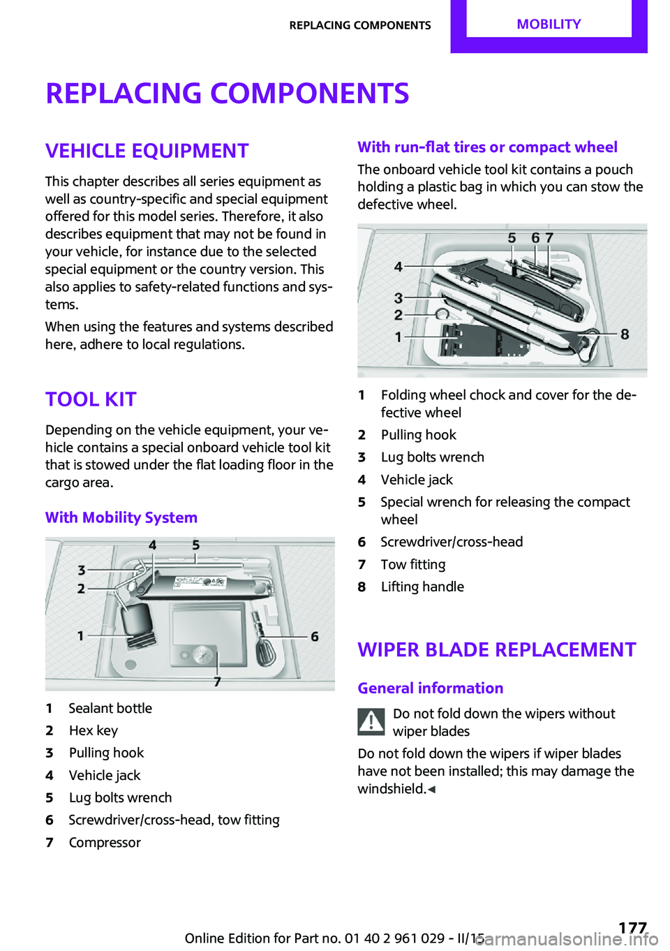
Depending on the vehicle equipment, your ve‐
hicle contains a special onboard vehicle tool kit
that is stowed under the flat loading floor in the
cargo area.
With Mobility System1Sealant bottle2Hex key3Pulling hook4Vehicle jack5Lug bolts wrench6Screwdriver/cross-head, tow fitting7CompressorWith run-flat tires or compact wheel
The onboard vehicle tool kit contains a pouch
holding a plastic bag in which you can stow the
defective wheel.1Folding wheel chock and cover for the de‐
fective wheel2Pulling hook3Lug bolts wrench4Vehicle jack5Special wrench for releasing the compact
wheel6Screwdriver/cross-head7Tow fitting8Lifting handle
Wiper blade replacement
General information Do not fold down the wipers withoutwiper blades
Do not fold down the wipers if wiper blades
have not been installed; this may damage the
windshield. ◀
Seite 177Replacing componentsMOBILITY177
Online Edition for Part no. 01 40 2 961 029 - II/15
Page 186 of 231
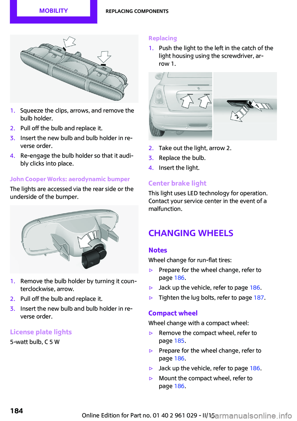
1.Squeeze the clips, arrows, and remove the
bulb holder.2.Pull off the bulb and replace it.3.Insert the new bulb and bulb holder in re‐
verse order.4.Re-engage the bulb holder so that it audi‐
bly clicks into place.
John Cooper Works: aerodynamic bumper
The lights are accessed via the rear side or the
underside of the bumper.
1.Remove the bulb holder by turning it coun‐
terclockwise, arrow.2.Pull off the bulb and replace it.3.Insert the new bulb and bulb holder in re‐
verse order.
License plate lights
5-watt bulb, C 5 W
Replacing1.Push the light to the left in the catch of the
light housing using the screwdriver, ar‐
row 1.2.Take out the light, arrow 2.3.Replace the bulb.4.Insert the light.
Center brake light
This light uses LED technology for operation.
Contact your service center in the event of a
malfunction.
Changing wheels NotesWheel change for run-flat tires:
▷Prepare for the wheel change, refer to
page 186.▷Jack up the vehicle, refer to page 186.▷Tighten the lug bolts, refer to page 187.
Compact wheel
Wheel change with a compact wheel:
▷Remove the compact wheel, refer to
page 185.▷Prepare for the wheel change, refer to
page 186.▷Jack up the vehicle, refer to page 186.▷Mount the compact wheel, refer to
page 186.Seite 184MOBILITYReplacing components184
Online Edition for Part no. 01 40 2 961 029 - II/15
Page 188 of 231
driving characteristics could result, for example
reduced track stability on braking, extended
braking distance, and altered self-steering
characteristics in the limit range. In conjunction
with winter tires, these characteristics are more
pronounced. ◀
Only mount one compact wheel
Only one compact wheel may be
mounted. Restore the wheels and tires to their
original size as quickly as possible. Failure to do
so is a safety risk. ◀
Check the tire inflation pressure at the next op‐
portunity and correct it if necessary. Replace
the defective tire as soon as possible and have
the new wheel balanced.
Preparing wheel change
Observe the safety precautions regarding flat
tires, refer to page 166.
Additional safety precautions in the event
of a wheel change
Change the wheel only on a level, firm surface
which is not slippery.
The vehicle or the jack could slip to the side if
you attempt to raise the vehicle on a soft or
slippery surface, snow, ice, tiles, etc. Do not use
a wooden block or similar object as a support
base for the jack, as this would prevent it from
extending to its full support height and reduce
its load-carrying capacity.
To avoid serious or fatal injury: never lie under
the vehicle, and never start the engine while it
is supported by the jack. ◀1.Place the folding wheel chock behind the
front wheel of the other vehicle side; if the
vehicle is on an incline, place it in front of
this wheel. If the vehicle is parked on a
steep incline, additionally secure the vehi‐
cle against rolling.2.Expose the lug bolts if necessary.3.Loosen the lug bolts a half turn.Jacking up vehicle
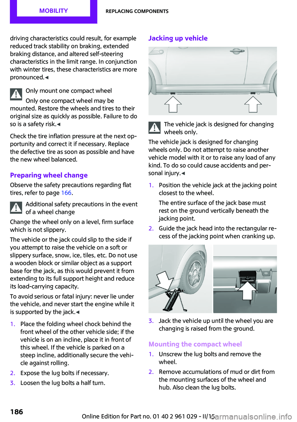
The vehicle jack is designed for changing
wheels only.
The vehicle jack is designed for changing
wheels only. Do not attempt to raise another
vehicle model with it or to raise any load of any
kind. To do so could cause accidents and per‐
sonal injury. ◀
1.Position the vehicle jack at the jacking point
closest to the wheel.
The entire surface of the jack base must
rest on the ground vertically beneath the
jacking point.2.Guide the jack head into the rectangular re‐
cess of the jacking point when cranking up.3.Jack the vehicle up until the wheel you are
changing is raised from the ground.
Mounting the compact wheel
1.Unscrew the lug bolts and remove the
wheel.2.Remove accumulations of mud or dirt from
the mounting surfaces of the wheel and
hub. Also clean the lug bolts.Seite 186MOBILITYReplacing components186
Online Edition for Part no. 01 40 2 961 029 - II/15
Page 216 of 231

Technical dataVehicle equipment
This chapter describes all series equipment as
well as country-specific and special equipment
offered for this model series. Therefore, it also
describes equipment that may not be found in
your vehicle, for instance due to the selectedspecial equipment or the country version. This
also applies to safety-related functions and sys‐
tems.
When using the features and systems described
here, adhere to local regulations.
Note
The technical data and specifications in this
Owner's Manual are used as guidance values.
The vehicle-specific data can deviate from this,
for example, due to the selected special equip‐
ment, country version or country-specific
measurement method. Detailed values can befound in the approval documents, on informa‐
tion signs on the vehicle or can be obtained
from the service center.
The information in the vehicle documents al‐
ways has priority.
Dimensions
The dimensions can vary depending on the
model version, equipment or country-specific
measurement method.
The specified heights do not take into account
attached parts, for example, a roof antenna,roof racks or spoiler. The heights can deviate,
for example, due to the selected special equip‐
ment, tires, load and chassis version.
MINI Coupe
MINI CoupeCooperCooper SJohn Cooper WorksWidth with mirrorsinches/mm74.5/1,89274.5/1,89274.5/1,892Width without mirrorsinches/mm66.3/1,68366.3/1,68366.3/1,683Height without roof antennainches/mm54.3/1,37854.5/1,38454.5/1,385Lengthinches/mm146.8/3,728147.0/3,734148.0/3,758Wheelbaseinches/mm97.1/2,46797.1/2,46797.1/2,467Smallest turning circle dia.ft/m35.1/10.735.1/10.735.1/10.7Seite 214REFERENCETechnical data214
Online Edition for Part no. 01 40 2 961 029 - II/15
Page 221 of 231
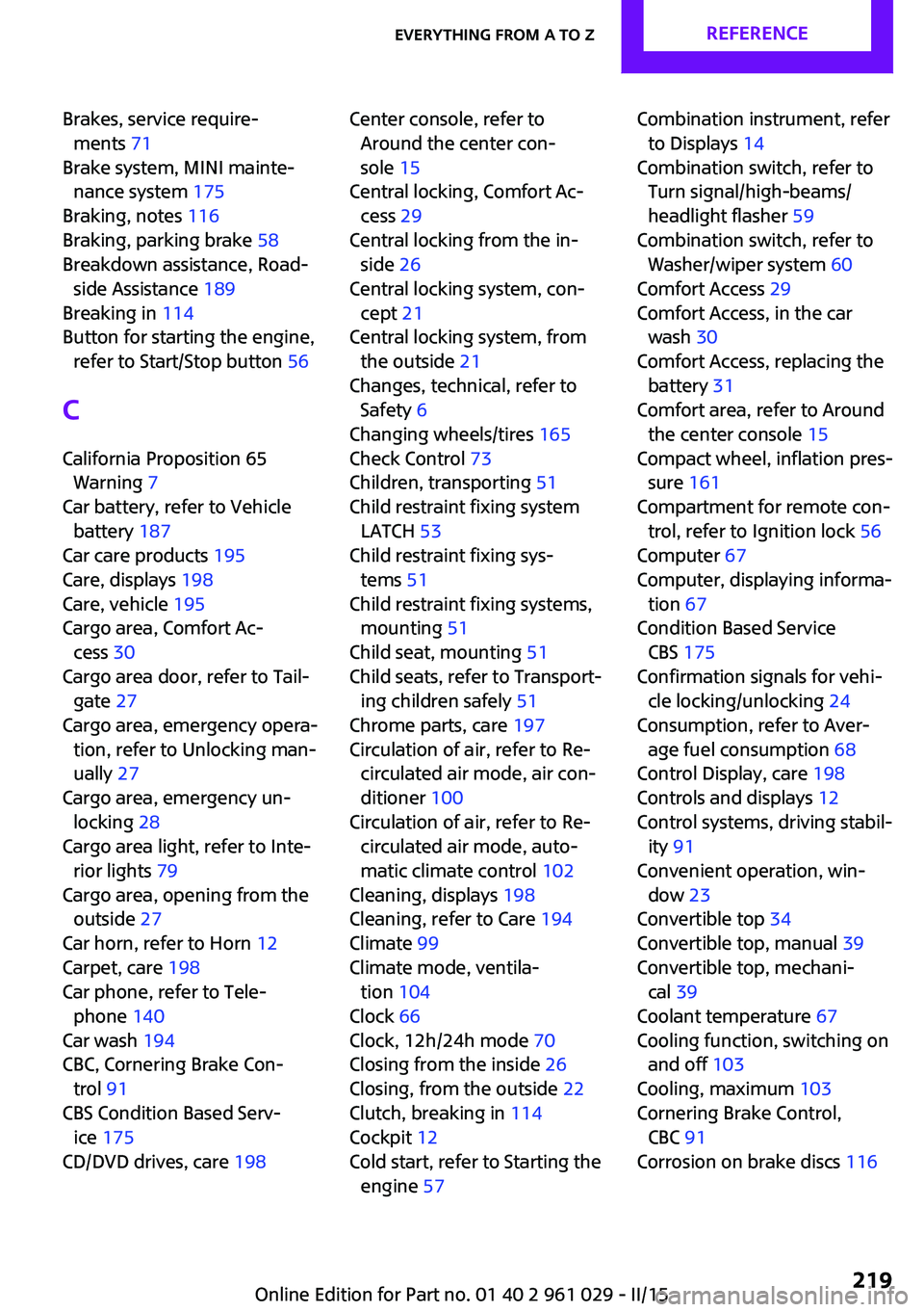
Brakes, service require‐ments 71
Brake system, MINI mainte‐ nance system 175
Braking, notes 116
Braking, parking brake 58
Breakdown assistance, Road‐ side Assistance 189
Breaking in 114
Button for starting the engine, refer to Start/Stop button 56
C
California Proposition 65 Warning 7
Car battery, refer to Vehicle battery 187
Car care products 195
Care, displays 198
Care, vehicle 195
Cargo area, Comfort Ac‐ cess 30
Cargo area door, refer to Tail‐ gate 27
Cargo area, emergency opera‐ tion, refer to Unlocking man‐
ually 27
Cargo area, emergency un‐ locking 28
Cargo area light, refer to Inte‐ rior lights 79
Cargo area, opening from the outside 27
Car horn, refer to Horn 12
Carpet, care 198
Car phone, refer to Tele‐ phone 140
Car wash 194
CBC, Cornering Brake Con‐ trol 91
CBS Condition Based Serv‐ ice 175
CD/DVD drives, care 198 Center console, refer to
Around the center con‐
sole 15
Central locking, Comfort Ac‐ cess 29
Central locking from the in‐ side 26
Central locking system, con‐ cept 21
Central locking system, from the outside 21
Changes, technical, refer to Safety 6
Changing wheels/tires 165
Check Control 73
Children, transporting 51
Child restraint fixing system LATCH 53
Child restraint fixing sys‐ tems 51
Child restraint fixing systems, mounting 51
Child seat, mounting 51
Child seats, refer to Transport‐ ing children safely 51
Chrome parts, care 197
Circulation of air, refer to Re‐ circulated air mode, air con‐
ditioner 100
Circulation of air, refer to Re‐ circulated air mode, auto‐
matic climate control 102
Cleaning, displays 198
Cleaning, refer to Care 194
Climate 99
Climate mode, ventila‐ tion 104
Clock 66
Clock, 12h/24h mode 70
Closing from the inside 26
Closing, from the outside 22
Clutch, breaking in 114
Cockpit 12
Cold start, refer to Starting the engine 57 Combination instrument, refer
to Displays 14
Combination switch, refer to Turn signal/high-beams/
headlight flasher 59
Combination switch, refer to Washer/wiper system 60
Comfort Access 29
Comfort Access, in the car wash 30
Comfort Access, replacing the battery 31
Comfort area, refer to Around the center console 15
Compact wheel, inflation pres‐ sure 161
Compartment for remote con‐ trol, refer to Ignition lock 56
Computer 67
Computer, displaying informa‐ tion 67
Condition Based Service CBS 175
Confirmation signals for vehi‐ cle locking/unlocking 24
Consumption, refer to Aver‐ age fuel consumption 68
Control Display, care 198
Controls and displays 12
Control systems, driving stabil‐ ity 91
Convenient operation, win‐ dow 23
Convertible top 34
Convertible top, manual 39
Convertible top, mechani‐ cal 39
Coolant temperature 67
Cooling function, switching on and off 103
Cooling, maximum 103
Cornering Brake Control, CBC 91
Corrosion on brake discs 116 Seite 219Everything from A to ZREFERENCE219
Online Edition for Part no. 01 40 2 961 029 - II/15
Page 223 of 231

Engine, starting, Comfort Ac‐cess 29
Engine, starting, Start/Stop button 56
Engine, stopping, Start/Stop button 56
Engine, switching off 58
ESP Electronic Stability Pro‐ gram, refer to Dynamic Sta‐
bility Control DSC 91
Exchanging wheels/tires 165
Exterior mirrors 49
Exterior mirrors, adjusting 49
Exterior mirrors, folding in and out 49
Exterior sensors, care 197
External temperature dis‐ play 66
External temperature display, changing the units 70
External temperature warn‐ ing 66
F Failure messages, refer to Check Control 73
False alarm, refer to Avoiding unintentional alarms 32
Fan, refer to Air flow rate for air conditioner 100
Fan, refer to Air flow rate with automatic climate con‐
trol 102
Fastening safety belts, refer to Safety belts 47
Fault messages, refer to Check Control 73
Filling capacities 217
Filter, refer to Activated-char‐ coal filter 101
Filter, refer to Microfilter 101
Filter, refer to Microfilter/acti‐ vated-charcoal filter with au‐
tomatic climate control 103
First aid kit 189 First aid, refer to First aid
kit 189
Flashing when locking/unlock‐ ing 24
Flat tire, Flat Tire Monitor 85
Flat tire, indicator/warning lamp 85
Flat Tire Monitor FTM 84
Flat Tire Monitor FTM, flat tire message 85
Flat Tire Monitor FTM, initializ‐ ing the system 84
Flat Tire Monitor FTM, snow chains 84
Flat Tire Monitor FTM, system limits 84
Flat tire, run-flat tire 85
Flat tire, Tire Pressure Moni‐ tor 86
Flat tire, Tire Pressure Monitor TPM 86
Flat tire, wheel change 184
Floor mats, care 198
Fog lights 78
Folding roof, refer to Convertible top with
integrated sliding sun‐
roof 34
Foot brake 116
Footwell lights, refer to Inte‐ rior lights 79
Front airbags 81
Front fog light, bulb replace‐ ment 181
Front fog lights 78
Front lights, bulb replace‐ ment 179
Front passenger airbags, de‐ activating 82
FTM Flat Tire Monitor 84
Fuel 154
Fuel, additives 154
Fuel, average consump‐ tion 68
Fuel cap, closing 152 Fuel consumption display,
average fuel consump‐
tion 68
Fuel filler flap, closing 152
Fuel filler flap, opening 152
Fuel filler flap, unlocking in case of an electrical malfunc‐
tion 152
Fuel gauge 67
Fuel, refer to Average fuel consumption 68
Fuel, saving 121
Fuel tank capacity, refer to Filling capacities 217
Fuel tank contents, refer to Filling capacities 217
Fuel tank, refer to Filling ca‐ pacities 217
Fuse 188
G
Gasoline 154
Gasoline gauge, refer to Fuel gauge 67
Gear change, manual trans‐ mission 62
Gear change, Steptronic trans‐ mission 63
Gear display, Steptronic trans‐ mission 63
Glare protection 105
H
Halogen headlights, bulb re‐ placement 180
Handbrake, refer to Parking brake 58
Hand car wash, care 195
Hands-free microphone 15
Hazard warning system 15
Head airbags 81
Headlamp control, refer to Parking lamps/low
beams 75 Seite 221Everything from A to ZREFERENCE221
Online Edition for Part no. 01 40 2 961 029 - II/15