2015 MINI COUPE ROADSTER CONVERTIBLE battery
[x] Cancel search: batteryPage 108 of 231
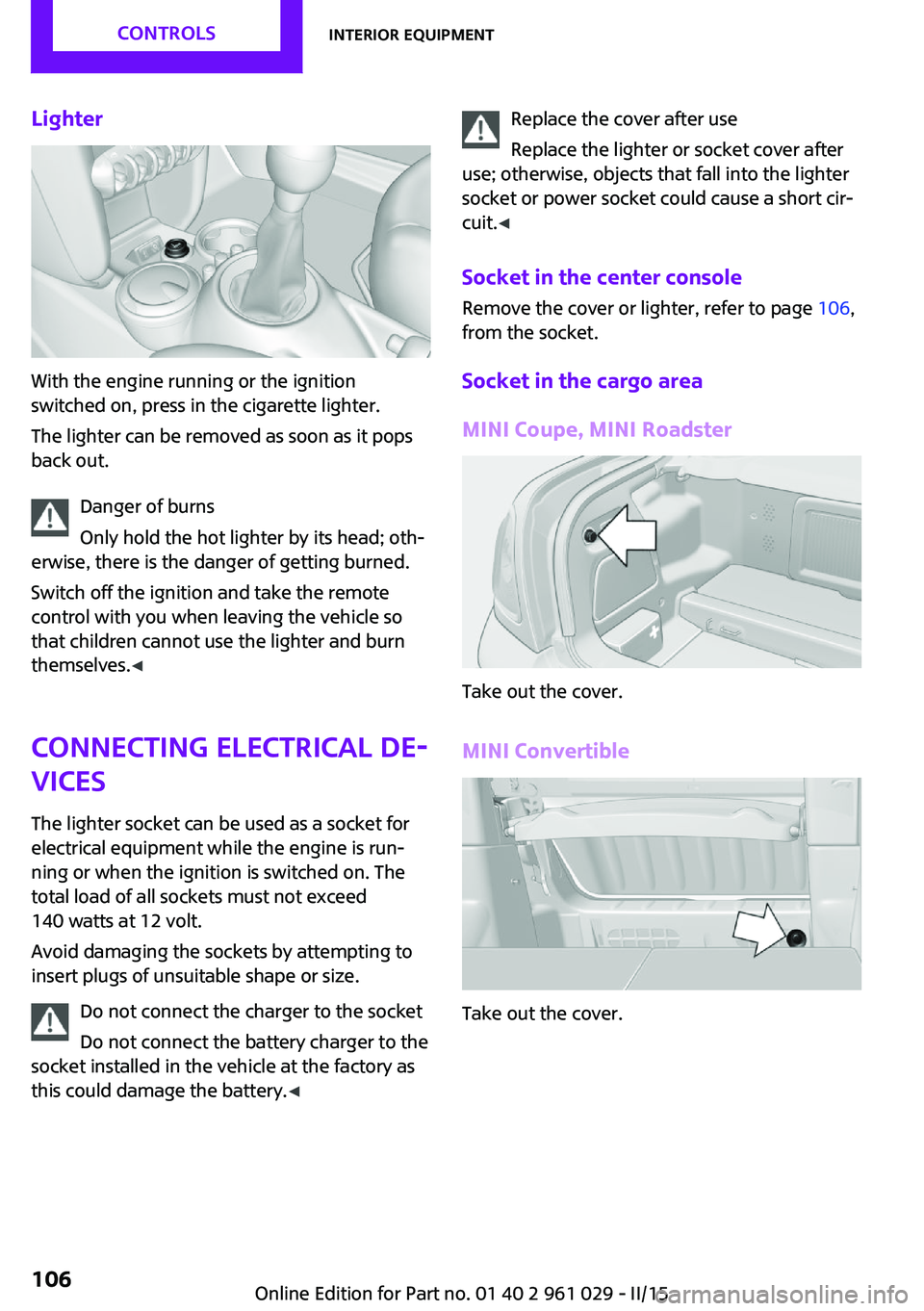
Lighter
With the engine running or the ignition
switched on, press in the cigarette lighter.
The lighter can be removed as soon as it pops
back out.
Danger of burns
Only hold the hot lighter by its head; oth‐
erwise, there is the danger of getting burned.
Switch off the ignition and take the remote
control with you when leaving the vehicle so
that children cannot use the lighter and burn
themselves. ◀
Connecting electrical de‐
vices
The lighter socket can be used as a socket for
electrical equipment while the engine is run‐
ning or when the ignition is switched on. The
total load of all sockets must not exceed
140 watts at 12 volt.
Avoid damaging the sockets by attempting to
insert plugs of unsuitable shape or size.
Do not connect the charger to the socket
Do not connect the battery charger to the
socket installed in the vehicle at the factory as this could damage the battery. ◀
Replace the cover after use
Replace the lighter or socket cover after
use; otherwise, objects that fall into the lighter
socket or power socket could cause a short cir‐
cuit. ◀
Socket in the center console
Remove the cover or lighter, refer to page 106,
from the socket.
Socket in the cargo area
MINI Coupe, MINI Roadster
Take out the cover.
MINI Convertible
Take out the cover.
Seite 106CONTROLSInterior equipment106
Online Edition for Part no. 01 40 2 961 029 - II/15
Page 130 of 231
for approx. 20 minutes. To listen to the radio,
switch it back on.
To spare the battery, ensure that the radio is
switched off when you leave the vehicle.
Adjusting the volume Turn the left knob. The setting is stored for the
remote control currently in use.
When a call is placed using the hands-free sys‐
tem, the audio sources are muted.
Speed-dependent volume and volumes
of PDC signal tone and gong▷"PDC": volume of the PDC signal tone com‐
pared to the audio sources.▷"GONG": volume of the gong compared to
the audio sources.▷"S-VOL": speed-dependent volume control.
Set the audio sources to a high volume to be
able to adjust the volume of the signal tones
more easily.
1. Press the button.2. Select the symbol if necessary.3.Select the desired volume setting.4.Set the desired volume and press the right
knob.
Volume of external audio devices
An external audio device such as an MP3 player
can be connected via the AUX-IN port in the
center console and the audio tracks can be
played over the car's loudspeaker system.
The volume of the external audio device can be
adjusted to the car radio.
1. Press the button.2."AUX"3."Vol-AUX"4.Set the desired volume and press the right
knob.Tone settings▷"BASS": depth adjustment.▷"TREBLE": treble adjustment.▷"FADER": front/rear volume distribution.▷"BAL": left/right volume distribution.
The sound settings are set globally for all audio
sources.
Setting the treble, bass, and volume distribution
1. Press the button.2.Highlight the desired tone setting and press
the right knob.3.Create the desired setting and press the
right knob.
Resetting the tone settings
The tone settings are reset to medium values.
1. Press the button.2."RESET"
Time
Setting the time, date, and time format
1.Switch on the radio ready state or the igni‐
tion.2. Press the button.3."CONFIG"4."TIME"5.Select the desired category.6.Create the settings and press the right
knob.Seite 128ENTERTAINMENTRadio MINI Boost CD128
Online Edition for Part no. 01 40 2 961 029 - II/15
Page 142 of 231
TelephoneVehicle equipment
This chapter describes all series equipment as
well as country-specific and special equipment
offered for this model series. Therefore, it also
describes equipment that may not be found in
your vehicle, for instance due to the selected
special equipment or the country version. This
also applies to safety-related functions and sys‐
tems.
When using the features and systems described
here, adhere to local regulations.
At a glance
The concept
Mobile phones can be connected with the vehi‐
cle via Bluetooth.
After a suitable mobile phone is paired with the
vehicle once, you can operate the mobile
phone via the radio and via the buttons on the
steering wheel.
Bluetooth® is a registered trademark of Blue‐
tooth® SIG, Inc.
Certain functions may need to be enabled by
the mobile phone provider or service provider.
Using the mobile phone while driving
Make entries only when traffic and road
conditions allow. Do not hold the mobile phone
in your hand while you are driving; use the
hands-free system instead. If you do not ob‐
serve this precaution, you can endanger the ve‐
hicle occupants and other road users. ◀
Snap-in adapter
The snap-in adapter is used to:▷Hold the mobile phone.▷Recharge the battery.▷Connect the mobile phone to an outside
antenna of the vehicle.
This provides for better network reception
and consistent sound quality.
Do not operate a mobile phone that is con‐
nected to the vehicle on the mobile phone key‐
pad, as this may lead to a malfunction.
Approved mobile phones
Details on which mobile phones with a Blue‐
tooth interface are supported by the mobile
phone preparation package can be obtained at
www.mini.com/connectivity.
Notes At high temperatures, the charging function of
the mobile phone may be limited and functions
may not be executed.
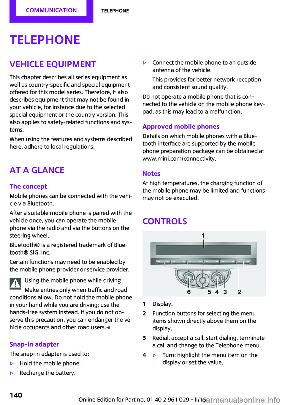
Controls
1Display.2Function buttons for selecting the menu
items shown directly above them on the
display.3Redial, accept a call, start dialing, terminate
a call and change to the Telephone menu.4▷Turn: highlight the menu item on the
display or set the value.Seite 140COMMUNICATIONTelephone140
Online Edition for Part no. 01 40 2 961 029 - II/15
Page 150 of 231
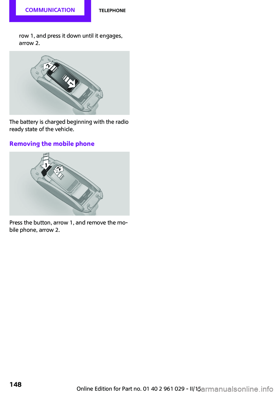
row 1, and press it down until it engages,
arrow 2.
The battery is charged beginning with the radio
ready state of the vehicle.
Removing the mobile phone
Press the button, arrow 1, and remove the mo‐
bile phone, arrow 2.
Seite 148COMMUNICATIONTelephone148
Online Edition for Part no. 01 40 2 961 029 - II/15
Page 172 of 231
Engine compartmentVehicle equipment
This chapter describes all series equipment as
well as country-specific and special equipment
offered for this model series. Therefore, it also
describes equipment that may not be found in
your vehicle, for instance due to the selectedspecial equipment or the country version. This
also applies to safety-related functions and sys‐
tems.
When using the features and systems described
here, adhere to local regulations.
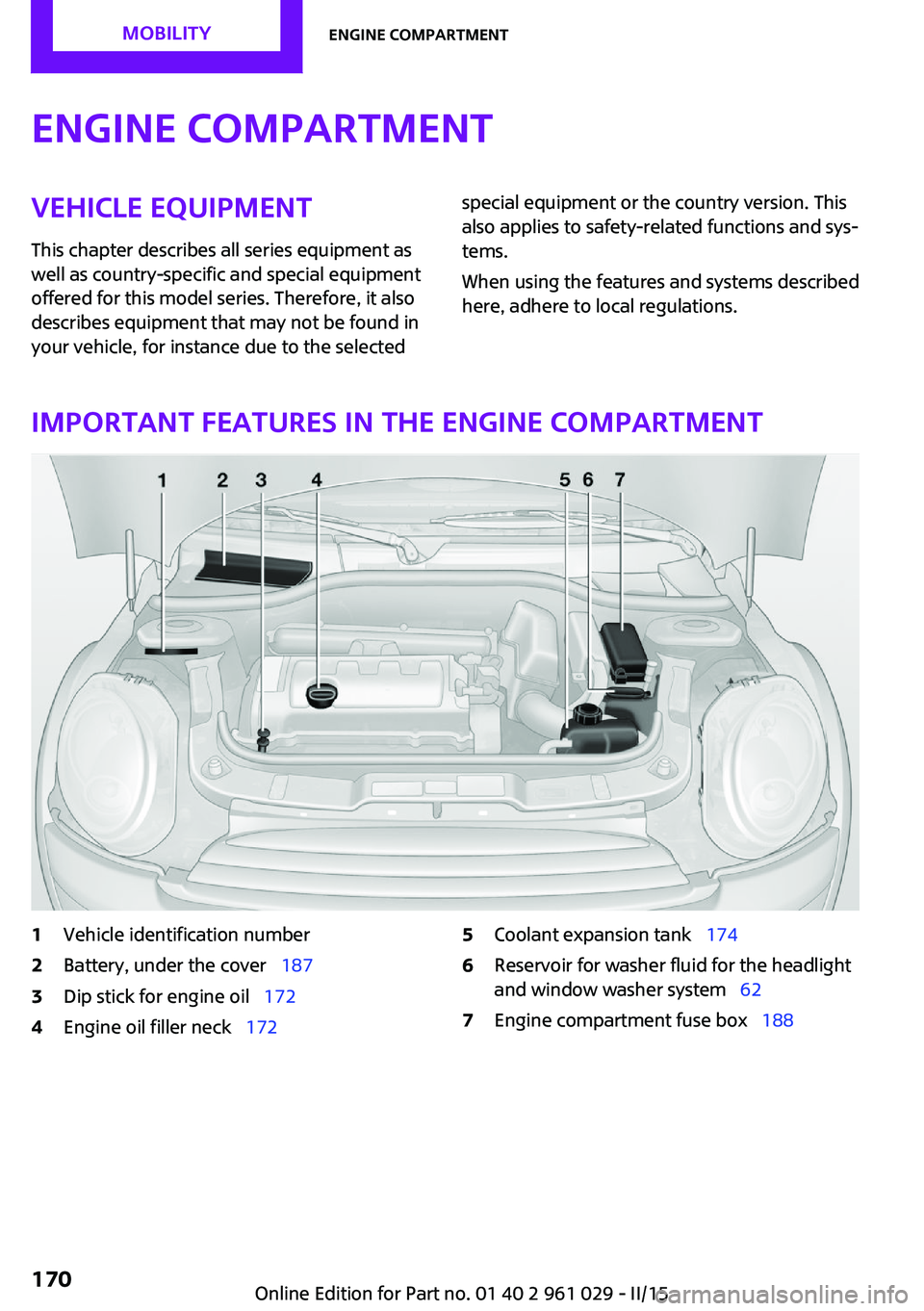
Important features in the engine compartment
1Vehicle identification number2Battery, under the cover 1873Dip stick for engine oil 1724Engine oil filler neck 1725Coolant expansion tank 1746Reservoir for washer fluid for the headlight
and window washer system 627Engine compartment fuse box 188Seite 170MOBILITYEngine compartment170
Online Edition for Part no. 01 40 2 961 029 - II/15
Page 189 of 231
3.Mount the new wheel.4.Screw in at least two bolts crosswise.5.Screw in the remaining lug bolts.6.Fully tighten all lug bolts in a diagonal pat‐
tern.7.Lower the vehicle.8.Remove the jack.
Retightening the lug bolts
Retighten the lug bolts diagonally.
Checking that the lug bolts are tight
Always have the lug bolts checked with a
calibrated torque wrench as soon as possible to
ensure that they are tightened to the specified
torque. Otherwise, incorrectly tightened lug
bolts are a hidden safety risk. ◀
The tightening torque equals
103.3 lb ft/140 Nm.
Replace the defective tire as soon as possible
and have the new wheel balanced.
Vehicle battery Maintenance
The battery is maintenance-free, i.e., the elec‐
trolyte will last for the life of the battery in tem‐
perate climate conditions.
The service center will be happy to answer any
questions on the battery.
Battery replacement Use approved vehicle batteries
Only use vehicle batteries that have been
approved for your vehicle by the manufacturer;
otherwise, the vehicle could be damaged and
systems or functions may not be fully availa‐
ble. ◀
Have the vehicle battery registered by the serv‐
ice center after it is replaced to ensure that all comfort functions are available without restric‐
tions and that any associated Check Control
messages are no longer displayed.
Charging the battery
Note Do not connect the charger to the socket
Do not connect the battery charger to the
socket installed in the vehicle at the factory as
this could damage the battery. ◀
Only charge the battery in the vehicle when the
engine is switched off. Connections, refer to
page 189.
General information Ensure that the battery is sufficiently charged to
achieve the full battery life.
It may be necessary to charge the battery in
the following cases:▷When the vehicle is frequently used to
travel short distances.▷When the vehicle has not been driven for
more than one month.
Power failure
After a temporary power failure, some equip‐
ment will be restricted in its use and will need
to be reinitialized. In addition, certain individual
settings will be lost and must be updated:
▷Time and date: the values must be up‐
dated, refer to page 71.▷Radio: the stations need to be stored again,
refer to page 130.
Disposing of old batteries
Have used batteries disposed of by the
service center after they are replaced or
take them to a recycling center.
Maintain the battery in an upright position for
transport and storage. Secure the battery so
that it does not tip over during transport.
Seite 187Replacing componentsMOBILITY187
Online Edition for Part no. 01 40 2 961 029 - II/15
Page 191 of 231

Breakdown assistanceVehicle equipment
This chapter describes all series equipment as
well as country-specific and special equipment
offered for this model series. Therefore, it also
describes equipment that may not be found in
your vehicle, for instance due to the selected
special equipment or the country version. This
also applies to safety-related functions and sys‐
tems.
When using the features and systems described
here, adhere to local regulations.
Hazard warning flash‐
ers
The button is located on the speedometer.
Warning triangle The warning triangle is located in the front on
the trunk floor.
First aid kit Some of the articles contained in the first aid kit
have a limited service life. Therefore, check the
use-by dates of the contents regularly and re‐
place the items before they expire.
The first aid kit is located in the left side trim on
the cargo area floor.
Roadside Assistance
Service availability Roadside Assistance can be reached around the
clock in many countries. You can obtain assis‐
tance there in the event of a vehicle break‐
down.
Roadside Assistance A phone number for Roadside Assistance can
be displayed, refer to page 146, via the radio.
Jump-starting Notes
If the battery is discharged, the engine can be
started using the battery of another vehicle and
two jumper cables. In the same way, you can
help jump-start another vehicle. Only use
jumper cables with fully insulated clamp han‐
dles.
To prevent personal injury or damage to both
vehicles, adhere strictly to the following proce‐
dure.
Seite 189Breakdown assistanceMOBILITY189
Online Edition for Part no. 01 40 2 961 029 - II/15
Page 192 of 231

Do not touch live parts
To avoid the risk of potentially fatal injury,
always avoid all contact with electrical compo‐
nents while the engine is running. ◀
Preparation1.Check whether the battery of the other ve‐
hicle has a voltage of 12 volts and approxi‐
mately the same capacitance in Ah. This in‐
formation can be found on the battery.2.Switch off the engine of the assisting vehi‐
cle.3.Switch off any electronic systems/power
consumers in both vehicles.
Bodywork contact between vehicles
There must not be any contact between
the bodies of the two vehicles, otherwise there
is a danger of shorting. ◀
Connecting jumper cables
Connecting order
Connect the jumper cables in the correct
order; otherwise, there is the danger of injury
from sparking. ◀1.Open the battery cover in the engine com‐
partment to access the positive terminal.2.Unlock the tabs of the positive terminal
cover on the left and right, arrows 1, and
raise the cover, arrow 2.3.Attach one terminal clamp of the positive
jumper cable to the positive terminal of the
battery or to a starting aid terminal of the
vehicle providing assistance.4.Attach the second clamp of the positive
jumper cable to the positive terminal of the
battery of the vehicle to be started.5.Attach one terminal clamp of the negative
jumper cable to the negative terminal of
the battery, or to the corresponding engine
or body ground of the vehicle providing as‐
sistance.6.Attach the second clamp of the negative
jumper cable to the negative terminal ofSeite 190MOBILITYBreakdown assistance190
Online Edition for Part no. 01 40 2 961 029 - II/15