2015 MINI COUPE ROADSTER CONVERTIBLE tow
[x] Cancel search: towPage 121 of 231
available cargo and luggage load capacity
calculated in Step 4.6.If your vehicle will be towing a trailer, load
from your trailer will be transfered to your
vehicle. Consult the manual for transporting
a trailer to determine how this may reduce
the available cargo and luggage load ca‐
pacity of your vehicle.
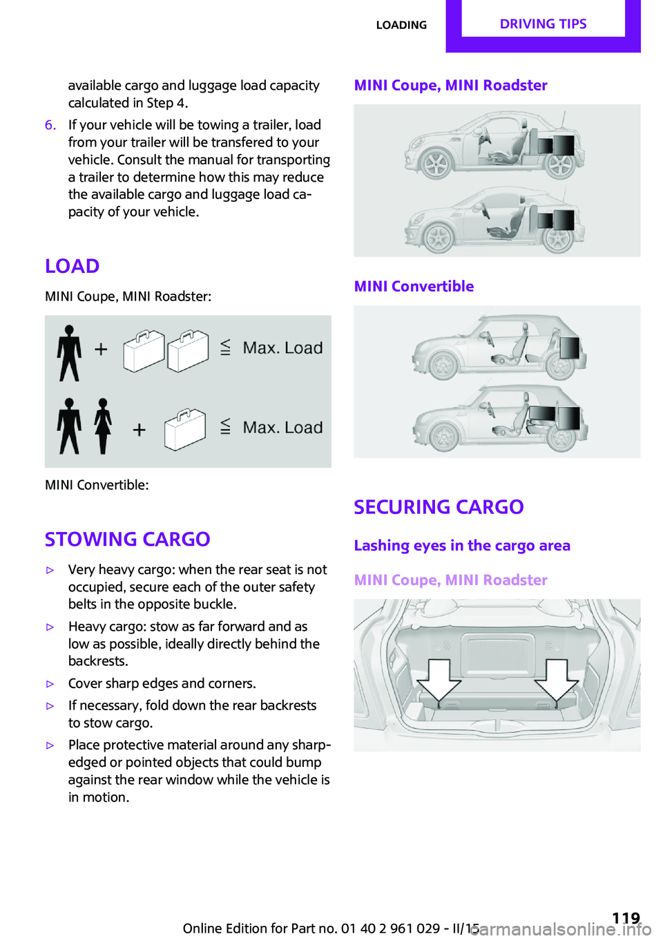
Load
MINI Coupe, MINI Roadster:
MINI Convertible:
Stowing cargo
▷Very heavy cargo: when the rear seat is not
occupied, secure each of the outer safety
belts in the opposite buckle.▷Heavy cargo: stow as far forward and as
low as possible, ideally directly behind the
backrests.▷Cover sharp edges and corners.▷If necessary, fold down the rear backrests
to stow cargo.▷Place protective material around any sharp-
edged or pointed objects that could bump
against the rear window while the vehicle is
in motion.MINI Coupe, MINI Roadster
MINI Convertible
Securing cargo
Lashing eyes in the cargo area
MINI Coupe, MINI Roadster
Seite 119LoadingDRIVING TIPS119
Online Edition for Part no. 01 40 2 961 029 - II/15
Page 122 of 231
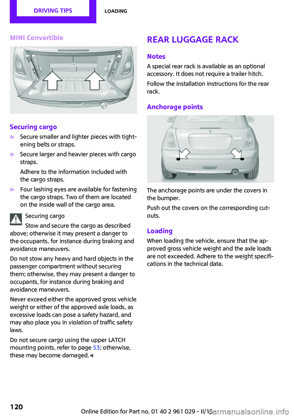
MINI Convertible
Securing cargo
▷Secure smaller and lighter pieces with tight‐
ening belts or straps.▷Secure larger and heavier pieces with cargo
straps.
Adhere to the information included with
the cargo straps.▷Four lashing eyes are available for fastening
the cargo straps. Two of them are located
on the inside wall of the cargo area.
Securing cargo
Stow and secure the cargo as described
above; otherwise it may present a danger to
the occupants, for instance during braking and
avoidance maneuvers.
Do not stow any heavy and hard objects in the
passenger compartment without securing
them; otherwise, they may present a danger to
occupants, for instance during braking and
avoidance maneuvers.
Never exceed either the approved gross vehicle
weight or either of the approved axle loads, as
excessive loads can pose a safety hazard, and
may also place you in violation of traffic safety
laws.
Do not secure cargo using the upper LATCH
mounting points, refer to page 53; otherwise,
these may become damaged. ◀
Rear luggage rack
Notes A special rear rack is available as an optional
accessory. It does not require a trailer hitch.
Follow the installation instructions for the rear
rack.
Anchorage points
The anchorage points are under the covers in
the bumper.
Push out the covers on the corresponding cut‐
outs.
Loading
When loading the vehicle, ensure that the ap‐
proved gross vehicle weight and the axle loads
are not exceeded. Adhere to the weight specifi‐
cations in the technical data.
Seite 120DRIVING TIPSLoading120
Online Edition for Part no. 01 40 2 961 029 - II/15
Page 149 of 231
▷"Road Assist": Roadside Assistance, if help
is required in the event of a breakdown.▷"Serv. Appt.": MINI service center, if a serv‐
ice appointment needs to be arranged.▷"Cust Relat": Customer Relations, for infor‐
mation on all aspects of your vehicle.
Displaying the phone numbers
1.Switch on the radio ready state or the igni‐
tion.2. Press the button.3."MINI"4.Turn the right knob until the desired phone
number is displayed.
Snap-in adapter
General information More information on compatible snap-in
adapters that support the functions of the mo‐
bile phone is available at the service center.
Notes At high temperatures, the charging function of
the mobile phone may be limited and functions
may not be executed.
When using the mobile phone via the vehicle,
note the operating instructions of the mobile
phone.
Installation position In the center armrest.
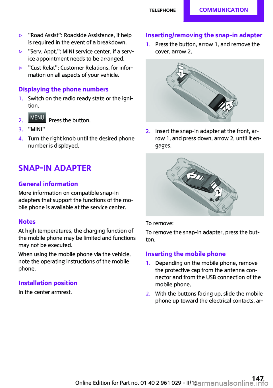
Inserting/removing the snap-in adapter1.Press the button, arrow 1, and remove the
cover, arrow 2.2.Insert the snap-in adapter at the front, ar‐
row 1, and press down, arrow 2, until it en‐
gages.
To remove:
To remove the snap-in adapter, press the but‐
ton.
Inserting the mobile phone
1.Depending on the mobile phone, remove
the protective cap from the antenna con‐
nector and from the USB connection of the
mobile phone.2.With the buttons facing up, slide the mobile
phone up toward the electrical contacts, ar‐Seite 147TelephoneCOMMUNICATION147
Online Edition for Part no. 01 40 2 961 029 - II/15
Page 166 of 231
for example, requires a minimum tread depth
of only 0.063 in/1.6 mm. At tread depths less
than 0.12 in/3 mm, there is a great danger of
hydroplaning even in low water depths and at
raised speeds.
Winter tires The suitability of winter tires for winter driving
is reduced noticeably when their tread depth
becomes less than 0.16 in/4 mm.
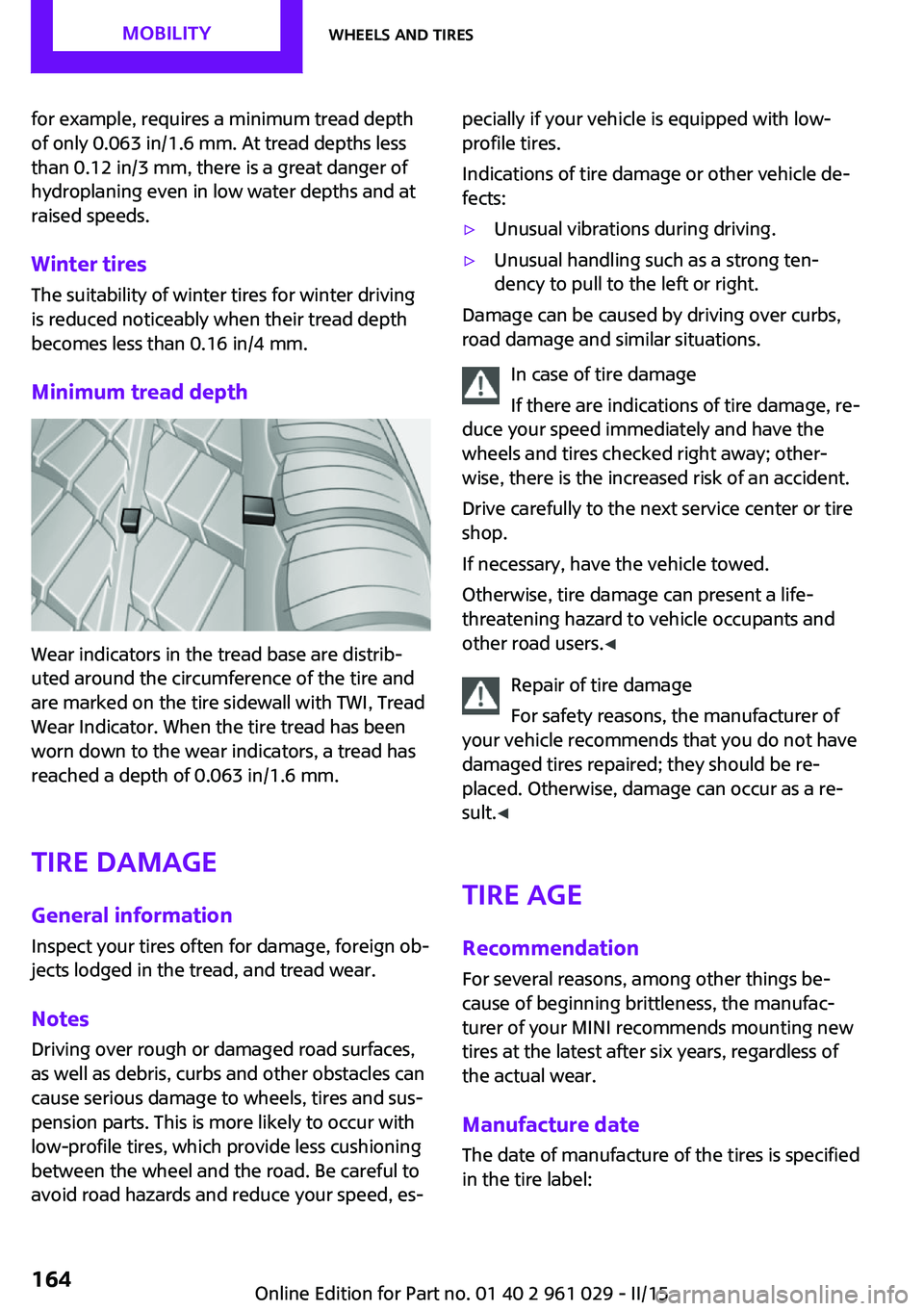
Minimum tread depth
Wear indicators in the tread base are distrib‐
uted around the circumference of the tire and
are marked on the tire sidewall with TWI, Tread
Wear Indicator. When the tire tread has been
worn down to the wear indicators, a tread has
reached a depth of 0.063 in/1.6 mm.
Tire damage
General information Inspect your tires often for damage, foreign ob‐
jects lodged in the tread, and tread wear.
Notes
Driving over rough or damaged road surfaces,
as well as debris, curbs and other obstacles can
cause serious damage to wheels, tires and sus‐
pension parts. This is more likely to occur with
low-profile tires, which provide less cushioning
between the wheel and the road. Be careful to
avoid road hazards and reduce your speed, es‐
pecially if your vehicle is equipped with low-
profile tires.
Indications of tire damage or other vehicle de‐
fects:▷Unusual vibrations during driving.▷Unusual handling such as a strong ten‐
dency to pull to the left or right.
Damage can be caused by driving over curbs,
road damage and similar situations.
In case of tire damage
If there are indications of tire damage, re‐
duce your speed immediately and have the
wheels and tires checked right away; other‐
wise, there is the increased risk of an accident.
Drive carefully to the next service center or tire
shop.
If necessary, have the vehicle towed.
Otherwise, tire damage can present a life-
threatening hazard to vehicle occupants and
other road users. ◀
Repair of tire damage
For safety reasons, the manufacturer of
your vehicle recommends that you do not have
damaged tires repaired; they should be re‐
placed. Otherwise, damage can occur as a re‐
sult. ◀
Tire age RecommendationFor several reasons, among other things be‐
cause of beginning brittleness, the manufac‐
turer of your MINI recommends mounting new
tires at the latest after six years, regardless of
the actual wear.
Manufacture date The date of manufacture of the tires is specified
in the tire label:
Seite 164MOBILITYWheels and tires164
Online Edition for Part no. 01 40 2 961 029 - II/15
Page 169 of 231
▷If a warning triangle or portable hazard
warning lamp is required, set it up on the
roadside at an appropriate distance from
the rear of the vehicle. Comply with all
safety guidelines and regulations. ◀
The procedure to correct a flat tire depends on
the equipment in the vehicle:
▷Run-flat tires, refer to page 166.▷MINI Mobility System, refer to page 167.▷Wheel change with a compact wheel, refer
to page 184.
MINI Mobility System
Notes
▷Follow the instructions on using the Mobi‐
lity System found on the compressor and
sealant bottle.▷Use of the Mobility System may be ineffec‐
tive if tire damage is greater than approx.
1/8 in/4 mm in size.▷Contact the nearest service center if the tire
cannot be made drivable.▷If possible, do not remove foreign bodies
that have penetrated the tire.▷Pull the speed limit sticker off the sealant
bottle and apply it to the steering wheel.
Sealant and compressor
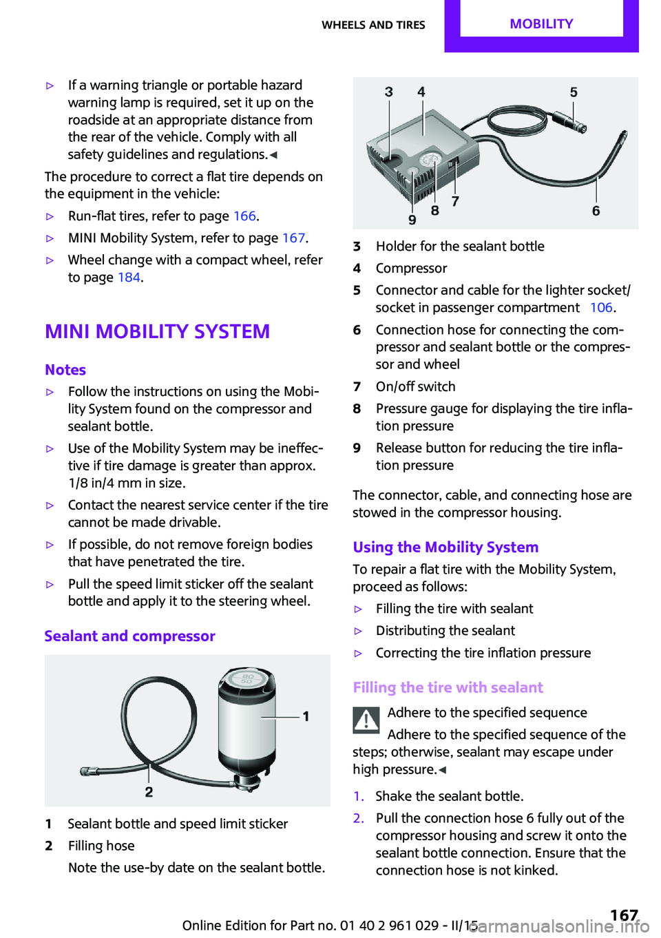
1Sealant bottle and speed limit sticker2Filling hose
Note the use-by date on the sealant bottle.3Holder for the sealant bottle4Compressor5Connector and cable for the lighter socket/
socket in passenger compartment 106.6Connection hose for connecting the com‐
pressor and sealant bottle or the compres‐
sor and wheel7On/off switch8Pressure gauge for displaying the tire infla‐
tion pressure9Release button for reducing the tire infla‐
tion pressure
The connector, cable, and connecting hose are
stowed in the compressor housing.
Using the Mobility System
To repair a flat tire with the Mobility System,
proceed as follows:
▷Filling the tire with sealant▷Distributing the sealant▷Correcting the tire inflation pressure
Filling the tire with sealant
Adhere to the specified sequence
Adhere to the specified sequence of the
steps; otherwise, sealant may escape under
high pressure. ◀
1.Shake the sealant bottle.2.Pull the connection hose 6 fully out of the
compressor housing and screw it onto the
sealant bottle connection. Ensure that the
connection hose is not kinked.Seite 167Wheels and tiresMOBILITY167
Online Edition for Part no. 01 40 2 961 029 - II/15
Page 170 of 231

3.Insert the sealant bottle into the compres‐
sor housing in a vertical position.4.Unscrew the dust cap off of the valve of the
defective wheel and screw the filling hose 2
of the sealant bottle onto the valve.5.Ensure that the compressor is switched off.6.Insert connector 5 into the lighter socket/
socket in the passenger compartment, refer
to page 106.7.When the engine is running:
Switch on the compressor and let it run for
approx. 3 to 8 minutes to fill sealant into
the tire and achieve a tire inflation pressure
of approx. 1.8 bar/26 psi.
While sealant is being filled, the inflation
pressure may intermittently rise to approx.
5 bar/73 psi. Do not switch off the com‐
pressor in this phase.8.Switch off the compressor.
Do not allow the compressor to run too
long
Do not allow the compressor to run longer than
10 minutes; otherwise, the device will overheat
and may be damaged. ◀
If an air pressure of 1.8 bar/26 psi is not
reached:
1.Unscrew the filling hose 2 from the wheel
and drive forward and back approx.
33 ft/10 m to evenly distribute the sealant
in the tire.2.Inflate the tire again using the compressor.If the inflation pressure of 1.8 bar/26 psi is still
not reached, the tire is too heavily damaged.
Contact the nearest service center.
Stowing the Mobility System1.Unscrew the filling hose 2 of the sealant
bottle from the wheel.2.Unscrew the compressor connection hose 6
from the sealant bottle.3.Connect the filling hose 2 of the sealant
bottle with the free connector on the seal‐
ant bottle.
This prevents left-over sealant from escap‐
ing from the bottle.4.Wrap the empty sealant bottle in suitable
material to avoid dirtying the cargo area.5.Stow the Mobility System back in the vehi‐
cle.
Distributing the sealant
Drive approx. 3.1 miles/5 km to evenly distrib‐
ute the sealant.
Do not exceed a speed of 50 mph/80 km/h. If
possible, do not drop below a speed of
10 mph/20 km/h.
Correcting the tire inflation pressure
1.After driving approx. 3.1 miles/5 km, or
about 10 minutes, stop in a suitable loca‐
tion.2.Screw the connection hose 6 of the com‐
pressor directly onto the tire valve.3.Insert the connector 5 into the power
socket in the passenger compartment.4.Correct the tire inflation pressure to
1.8 bar/26 psi. When the engine is running:▷To increase the inflation pressure:
switch on the compressor. To check the
currently set inflation pressure, switch
off the compressor.▷To reduce the inflation pressure: press
the release button 9.Seite 168MOBILITYWheels and tires168
Online Edition for Part no. 01 40 2 961 029 - II/15
Page 174 of 231
Engine oilEngine oil
Vehicle equipment This chapter describes all series equipment as
well as country-specific and special equipment
offered for this model series. Therefore, it also
describes equipment that may not be found in
your vehicle, for instance due to the selected
special equipment or the country version. This
also applies to safety-related functions and sys‐
tems.
When using the features and systems described
here, adhere to local regulations.
General information
Engine oil consumption depends on the driving
style and the conditions of use. A highly sporty
driving style, for example, results in considera‐
bly higher engine oil consumption.
Therefore, regularly check the engine oil level
after refueling.
Checking the oil level with a dip stick1.Park the vehicle on level ground when the
engine is at operating temperature, i.e., af‐
ter driving continuously for at least
6 2 miles/10 km.2.Switch the engine off.3.After approx. 5 minutes, pull out the dip
stick and wipe it off with a lint-free cloth,
paper towel, etc.4.Carefully insert the dip stick all the way into
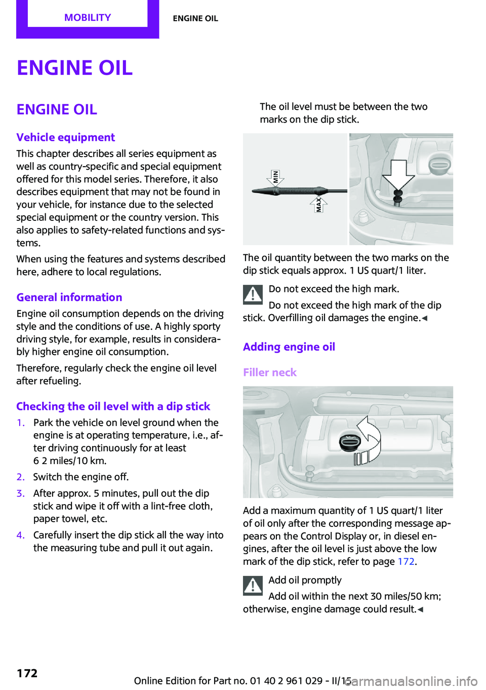
the measuring tube and pull it out again.The oil level must be between the two
marks on the dip stick.
The oil quantity between the two marks on the
dip stick equals approx. 1 US quart/1 liter.
Do not exceed the high mark.
Do not exceed the high mark of the dip
stick. Overfilling oil damages the engine. ◀
Adding engine oil
Filler neck
Add a maximum quantity of 1 US quart/1 liter
of oil only after the corresponding message ap‐
pears on the Control Display or, in diesel en‐
gines, after the oil level is just above the low
mark of the dip stick, refer to page 172.
Add oil promptly
Add oil within the next 30 miles/50 km;
otherwise, engine damage could result. ◀
Seite 172MOBILITYEngine oil172
Online Edition for Part no. 01 40 2 961 029 - II/15
Page 179 of 231
Replacing componentsVehicle equipmentThis chapter describes all series equipment as
well as country-specific and special equipment
offered for this model series. Therefore, it also
describes equipment that may not be found in
your vehicle, for instance due to the selected
special equipment or the country version. This
also applies to safety-related functions and sys‐
tems.
When using the features and systems described
here, adhere to local regulations.
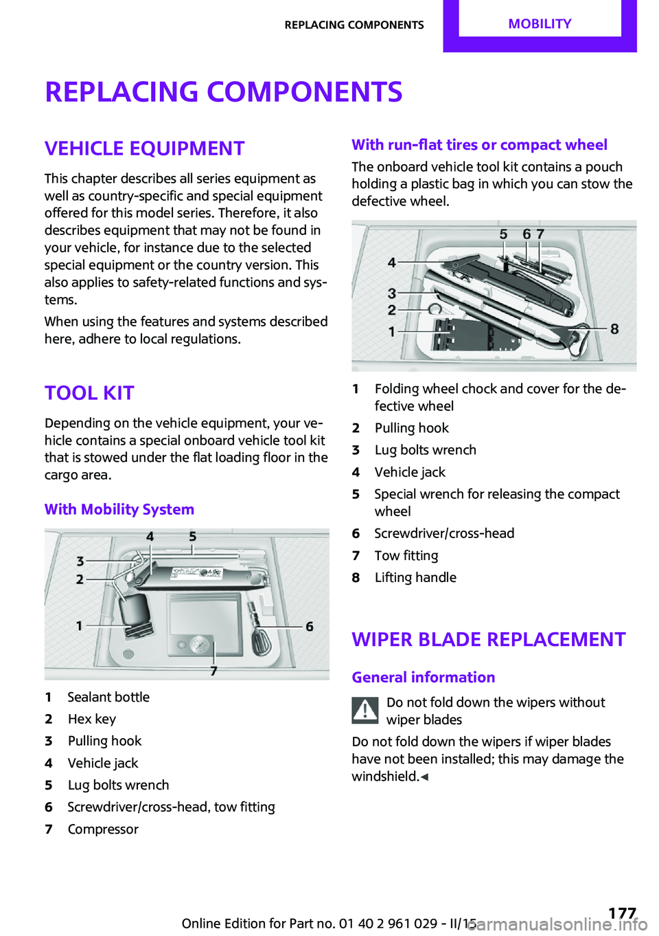
Tool kit
Depending on the vehicle equipment, your ve‐
hicle contains a special onboard vehicle tool kit
that is stowed under the flat loading floor in the
cargo area.
With Mobility System1Sealant bottle2Hex key3Pulling hook4Vehicle jack5Lug bolts wrench6Screwdriver/cross-head, tow fitting7CompressorWith run-flat tires or compact wheel
The onboard vehicle tool kit contains a pouch
holding a plastic bag in which you can stow the
defective wheel.1Folding wheel chock and cover for the de‐
fective wheel2Pulling hook3Lug bolts wrench4Vehicle jack5Special wrench for releasing the compact
wheel6Screwdriver/cross-head7Tow fitting8Lifting handle
Wiper blade replacement
General information Do not fold down the wipers withoutwiper blades
Do not fold down the wipers if wiper blades
have not been installed; this may damage the
windshield. ◀
Seite 177Replacing componentsMOBILITY177
Online Edition for Part no. 01 40 2 961 029 - II/15