2015 MINI COUPE ROADSTER CONVERTIBLE belt
[x] Cancel search: beltPage 55 of 231
3.Allow the belt webbing to be pulled in com‐
pletely.
Guide the safety belt to the holder on the
headliner.
MINI Convertible: LATCH
child restraint fixing
system
LATCH: Lower Anchors and Tethers for Children.
Notes Manufacturer's information for LATCH
child restraint fixing systems
To mount and use the LATCH child restraint fix‐
ing systems, observe the operating and safety
information from the system manufacturer;
otherwise, the level of protection may be re‐
duced. ◀
Mounts for the lower LATCH anchors
The lower anchors may be used to attach the
CRS to the vehicle seat up to a combined child
and CRS weight of 65 lb/30 kg when the child is
restrained by the internal harnesses.
Correctly engage the lower LATCH an‐
chors
Make sure that the lower LATCH anchors have
properly engaged and that the child restraint
fixing system is resting snugly against the back‐
rest; otherwise, the degree of protection of‐
fered may be reduced. ◀
Before installing the child seat, pull the belt out
of the area for the child restraint fixing system.
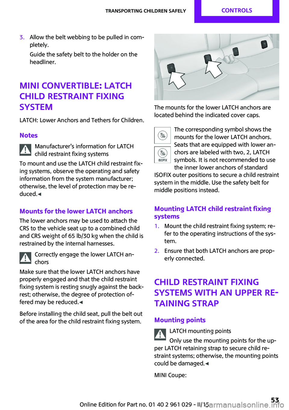
The mounts for the lower LATCH anchors are
located behind the indicated cover caps.
The corresponding symbol shows the
mounts for the lower LATCH anchors.
Seats that are equipped with lower an‐
chors are labeled with two, 2, LATCH
symbols. It is not recommended to use
the inner lower anchors of standard
ISOFIX outer positions to secure a child restraint
system in the middle. Use the safety belt for
middle positions instead.
Mounting LATCH child restraint fixing
systems
1.Mount the child restraint fixing system; re‐
fer to the operating instructions of the sys‐
tem.2.Ensure that both LATCH anchors are prop‐
erly connected.
Child restraint fixing
systems with an upper re‐
taining strap
Mounting points LATCH mounting points
Only use the mounting points for the up‐
per LATCH retaining strap to secure child re‐
straint systems; otherwise, the mounting points
could be damaged. ◀
MINI Coupe:
Seite 53Transporting children safelyCONTROLS53
Online Edition for Part no. 01 40 2 961 029 - II/15
Page 83 of 231
SafetyVehicle equipment
This chapter describes all series equipment as
well as country-specific and special equipment
offered for this model series. Therefore, it also
describes equipment that may not be found in
your vehicle, for instance due to the selected
special equipment or the country version. This
also applies to safety-related functions and sys‐
tems.
When using the features and systems described
here, adhere to local regulations.
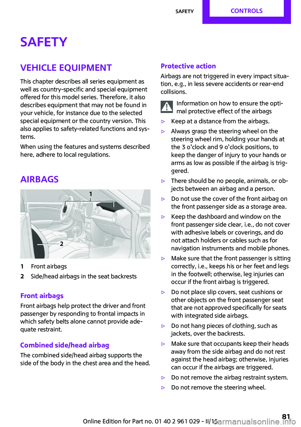
Airbags1Front airbags2Side/head airbags in the seat backrests
Front airbags
Front airbags help protect the driver and front
passenger by responding to frontal impacts in
which safety belts alone cannot provide ade‐
quate restraint.
Combined side/head airbag
The combined side/head airbag supports the
side of the body in the chest area and the head.
Protective action
Airbags are not triggered in every impact situa‐
tion, e.g., in less severe accidents or rear-end
collisions.
Information on how to ensure the opti‐
mal protective effect of the airbags▷Keep at a distance from the airbags.▷Always grasp the steering wheel on the
steering wheel rim, holding your hands at
the 3 o'clock and 9 o'clock positions, to
keep the danger of injury to your hands or
arms as low as possible if the airbag is trig‐
gered.▷There should be no people, animals, or ob‐
jects between an airbag and a person.▷Do not use the cover of the front airbag on
the front passenger side as a storage area.▷Keep the dashboard and window on the
front passenger side clear, i.e., do not cover
with adhesive labels or coverings, and do
not attach holders or cables such as for
navigation instruments and mobile phones.▷Make sure that the front passenger is sitting
correctly, i.e., keeps his or her feet and legs
in the footwell; otherwise, leg injuries can
occur if the front airbag is triggered.▷Do not place slip covers, seat cushions or
other objects on the front passenger seat
that are not approved specifically for seats
with integrated side airbags.▷Do not hang pieces of clothing, such as
jackets, over the backrests.▷Make sure that occupants keep their heads
away from the side airbag and do not rest
against the head airbag; otherwise, injuries
can occur if the airbags are triggered.▷Do not remove the airbag restraint system.▷Do not remove the steering wheel.Seite 81SafetyCONTROLS81
Online Edition for Part no. 01 40 2 961 029 - II/15
Page 85 of 231
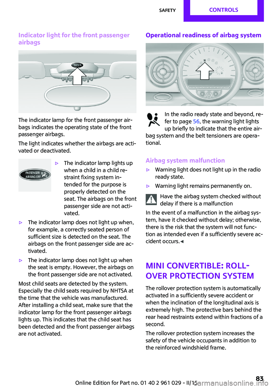
Indicator light for the front passengerairbags
The indicator lamp for the front passenger air‐
bags indicates the operating state of the front
passenger airbags.
The light indicates whether the airbags are acti‐
vated or deactivated.
▷The indicator lamp lights up
when a child in a child re‐
straint fixing system in‐
tended for the purpose is
properly detected on the
seat. The airbags on the front
passenger side are not acti‐
vated.▷The indicator lamp does not light up when,
for example, a correctly seated person of
sufficient size is detected on the seat. The
airbags on the front passenger side are ac‐
tivated.▷The indicator lamp does not light up when
the seat is empty. However, the airbags on
the front passenger side are not activated.
Most child seats are detected by the system.
Especially the child seats required by NHTSA at
the time that the vehicle was manufactured.
After installing a child seat, make sure that the
indicator lamp for the front passenger airbags
lights up. This indicates that the child seat has
been detected and the front passenger airbags
are not activated.
Operational readiness of airbag system
In the radio ready state and beyond, re‐
fer to page 56, the warning light lights
up briefly to indicate that the entire air‐
bag system and the belt tensioners are opera‐
tional.
Airbag system malfunction
▷Warning light does not light up in the radio
ready state.▷Warning light remains permanently on.
Have the airbag system checked without
delay if there is a malfunction
In the event of a malfunction in the airbag sys‐
tem, have it checked without delay; otherwise,
there is the risk that the system will not func‐
tion as intended even if a sufficiently severe ac‐
cident occurs. ◀
MINI Convertible: roll‐
over protection system
The rollover protection system is automatically
activated in a sufficiently severe accident or
when the inclination of the longitudinal axis is
extremely high. The protective bars behind the
rear head restraints extend within fractions of a
second.
The rollover protection system increases the
safety of the vehicle occupants in addition to
the reinforced windshield frame.
Seite 83SafetyCONTROLS83
Online Edition for Part no. 01 40 2 961 029 - II/15
Page 86 of 231

Do not obstruct the area of movement
Always keep the area of movement of the
rollover protection system clear. In light acci‐
dents, you are protected by the fastened safety
belt and, depending on the severity of the acci‐
dent, the belt tightener and the multi-level air
bag restraint system. ◀
Lowering
Have the service center check the rollover pro‐
tection system after it is deployed unexpect‐
edly.
General instructions on the rollover pro‐
tection system
When the rollover protection system is ex‐
tended, do not move the convertible top under
any circumstances.
Do not modify the individual components of
the rollover protection system or the wiring in
any way.
Work on the rollover protection system should only be performed by a MINI service center.
Non-professional work on the system could
lead to failure or a malfunction.
To check the system and to ensure that the sys‐
tem will operate properly over the long-term, it
is imperative that you adhere to the specified
service intervals. ◀
FTM Flat Tire Monitor
The concept
The system does not measure the actual infla‐
tion pressure in the tires.
The system detects a pressure loss in a tire by
comparing the rotational speeds of the individ‐
ual wheels while moving.
In the event of a pressure loss, the diameter
and therefore the rotational speed of the corre‐
sponding wheel change. This is detected and
reported as a flat tire.Functional requirements
The system must have been initialized when
the tire inflation pressure was correct; other‐
wise, reliable signaling of a flat tire is not en‐
sured.
Initialize the system after each correction of the
tire inflation pressure and after every tire or
wheel change.
System limits Sudden tire damage
Sudden serious tire damage caused by
external influences cannot be indicated in ad‐
vance. ◀
A natural, even pressure loss in all four tires
cannot be detected. Therefore, check the tire
inflation pressure regularly.
The system could be delayed or malfunction in
the following situations:▷When the system has not been initialized.▷When driving on a snowy or slippery road
surface.▷Sporty driving style: slip in the drive wheels,
high lateral acceleration.▷When driving with snow chains.
When the vehicle is driven with a compact
wheel, refer to page 185, the Flat Tire Monitor
is not functional.
InitializationThe initialization process adopts the set infla‐
tion tire pressures as reference values for the
detection of a flat tire. Initialization is started by
confirming the inflation pressures.
Seite 84CONTROLSSafety84
Online Edition for Part no. 01 40 2 961 029 - II/15
Page 110 of 231
MINI Convertible: cargo areaDo not place objects on the cargo cover
Do not place objects on the cargo cover;
otherwise, the cover or the convertible top
could be damaged. ◀
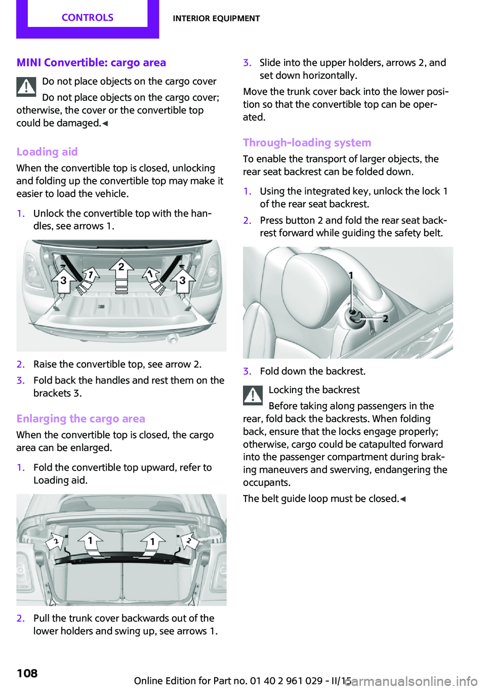
Loading aid When the convertible top is closed, unlocking
and folding up the convertible top may make it
easier to load the vehicle.1.Unlock the convertible top with the han‐
dles, see arrows 1.2.Raise the convertible top, see arrow 2.3.Fold back the handles and rest them on the
brackets 3.
Enlarging the cargo area
When the convertible top is closed, the cargo
area can be enlarged.
1.Fold the convertible top upward, refer to
Loading aid.2.Pull the trunk cover backwards out of the
lower holders and swing up, see arrows 1.3.Slide into the upper holders, arrows 2, and
set down horizontally.
Move the trunk cover back into the lower posi‐
tion so that the convertible top can be oper‐
ated.
Through-loading system
To enable the transport of larger objects, the
rear seat backrest can be folded down.
1.Using the integrated key, unlock the lock 1
of the rear seat backrest.2.Press button 2 and fold the rear seat back‐
rest forward while guiding the safety belt.3.Fold down the backrest.
Locking the backrest
Before taking along passengers in the
rear, fold back the backrests. When folding
back, ensure that the locks engage properly;
otherwise, cargo could be catapulted forward
into the passenger compartment during brak‐
ing maneuvers and swerving, endangering the
occupants.
The belt guide loop must be closed. ◀
Seite 108CONTROLSInterior equipment108
Online Edition for Part no. 01 40 2 961 029 - II/15
Page 121 of 231
available cargo and luggage load capacity
calculated in Step 4.6.If your vehicle will be towing a trailer, load
from your trailer will be transfered to your
vehicle. Consult the manual for transporting
a trailer to determine how this may reduce
the available cargo and luggage load ca‐
pacity of your vehicle.
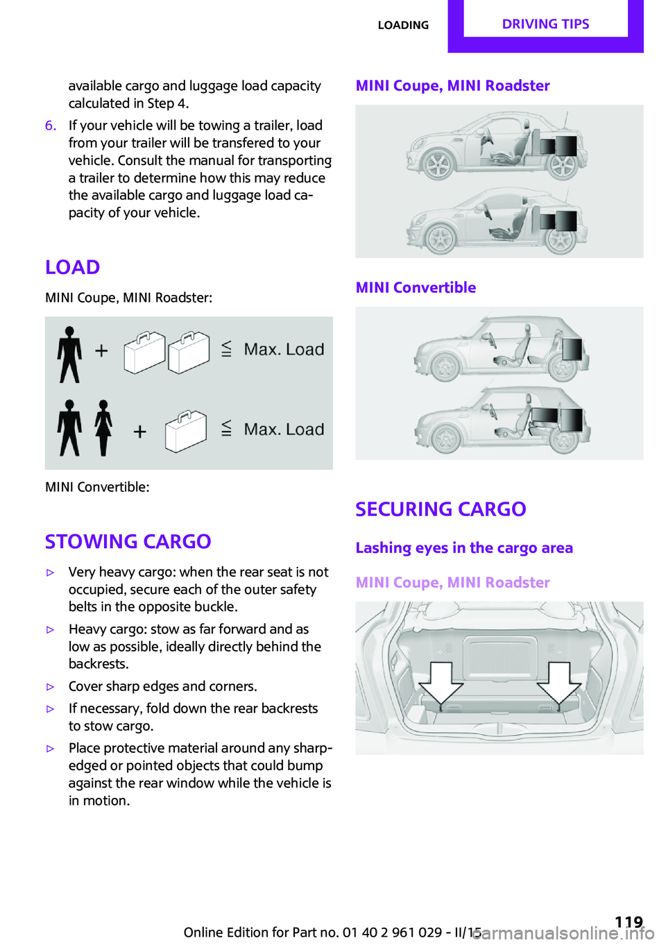
Load
MINI Coupe, MINI Roadster:
MINI Convertible:
Stowing cargo
▷Very heavy cargo: when the rear seat is not
occupied, secure each of the outer safety
belts in the opposite buckle.▷Heavy cargo: stow as far forward and as
low as possible, ideally directly behind the
backrests.▷Cover sharp edges and corners.▷If necessary, fold down the rear backrests
to stow cargo.▷Place protective material around any sharp-
edged or pointed objects that could bump
against the rear window while the vehicle is
in motion.MINI Coupe, MINI Roadster
MINI Convertible
Securing cargo
Lashing eyes in the cargo area
MINI Coupe, MINI Roadster
Seite 119LoadingDRIVING TIPS119
Online Edition for Part no. 01 40 2 961 029 - II/15
Page 122 of 231
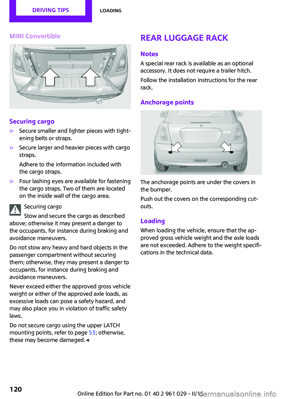
MINI Convertible
Securing cargo
▷Secure smaller and lighter pieces with tight‐
ening belts or straps.▷Secure larger and heavier pieces with cargo
straps.
Adhere to the information included with
the cargo straps.▷Four lashing eyes are available for fastening
the cargo straps. Two of them are located
on the inside wall of the cargo area.
Securing cargo
Stow and secure the cargo as described
above; otherwise it may present a danger to
the occupants, for instance during braking and
avoidance maneuvers.
Do not stow any heavy and hard objects in the
passenger compartment without securing
them; otherwise, they may present a danger to
occupants, for instance during braking and
avoidance maneuvers.
Never exceed either the approved gross vehicle
weight or either of the approved axle loads, as
excessive loads can pose a safety hazard, and
may also place you in violation of traffic safety
laws.
Do not secure cargo using the upper LATCH
mounting points, refer to page 53; otherwise,
these may become damaged. ◀
Rear luggage rack
Notes A special rear rack is available as an optional
accessory. It does not require a trailer hitch.
Follow the installation instructions for the rear
rack.
Anchorage points
The anchorage points are under the covers in
the bumper.
Push out the covers on the corresponding cut‐
outs.
Loading
When loading the vehicle, ensure that the ap‐
proved gross vehicle weight and the axle loads
are not exceeded. Adhere to the weight specifi‐
cations in the technical data.
Seite 120DRIVING TIPSLoading120
Online Edition for Part no. 01 40 2 961 029 - II/15
Page 199 of 231

Make especially sure that light-colored leather
is cleaned regularly as it is more susceptible to
soiling.
Twice a year, treat the leather with a leather lo‐
tion as dirt and grease will attack the protective
layer of the leather.
Upholstery material care
Vacuum regularly with a vacuum cleaner to re‐
move superficial soiling.
In case of heavy soiling, e.g., beverage stains,
use a soft sponge or lint-free microfiber cloth in
combination with a suitable interior cleaner.
Follow the instructions on the container.
Clean the upholstery material down to the
seams using large sweeping motions. Avoid
rubbing the material vigorously.
Damage from Velcro® fasteners
Open Velcro® fasteners on pants or other
articles of clothing can damage the seat covers.
Ensure that any Velcro® fasteners are closed. ◀
Caring for special components
Interior plastic parts These include:▷Imitation leather surfaces▷Lamp lenses▷Indicator covers▷Matte components
Clean with water and a solvent-free plastic
cleaner if necessary.
Do not use cleansers that contain alcohol
or solvents
Do not use cleansers that contain alcohol or
solvents, such as lacquer thinners, heavy-duty
grease removers, fuel, or such; this could lead
to surface damage. ◀
Rubber seals Only treat with water or a rubber care product.
When cleaning rubber seals, do not use silicone
sprays or other care products containing sili‐
cone; otherwise, noise and damage may result.
Chrome surfaces Carefully clean components such as the radia‐
tor grille or door handles with an ample supply
of water, possibly with shampoo added, partic‐
ularly when they have been exposed to road
salt. For additional treatment, use a chrome
polish.
Light-alloy wheels When cleaning the wheels on the vehicle, only
use a neutral wheel rim cleaner with a pH value
of 5 to 9.
Do not use abrasive cleaners or a steam jet hot‐
ter than 140 ℉/60 ℃; otherwise, damage may
result. Adhere to the manufacturer instructions.
Aggressive, acidic, or alkaline cleaners may de‐
stroy the protective coating of neighboring
components such as the brake disc.
Exterior sensors The sensors on the outside of the vehicle, such
as for Park Distance Control, must be kept clean
and free of ice to ensure that they remain fully
functional.
Decorative trim Clean decorative trims and fine wood compo‐
nents with a moist cloth only. Then dry with a
soft cloth.
Safety belts Dirty belt straps impede the reeling action and
thus have a negative impact on safety.
No chemical cleaning
Do not clean chemically; this can destroy
the webbing. ◀Seite 197CareMOBILITY197
Online Edition for Part no. 01 40 2 961 029 - II/15