2015 MINI COOPER CONVERTIBLE inflation pressure
[x] Cancel search: inflation pressurePage 164 of 231

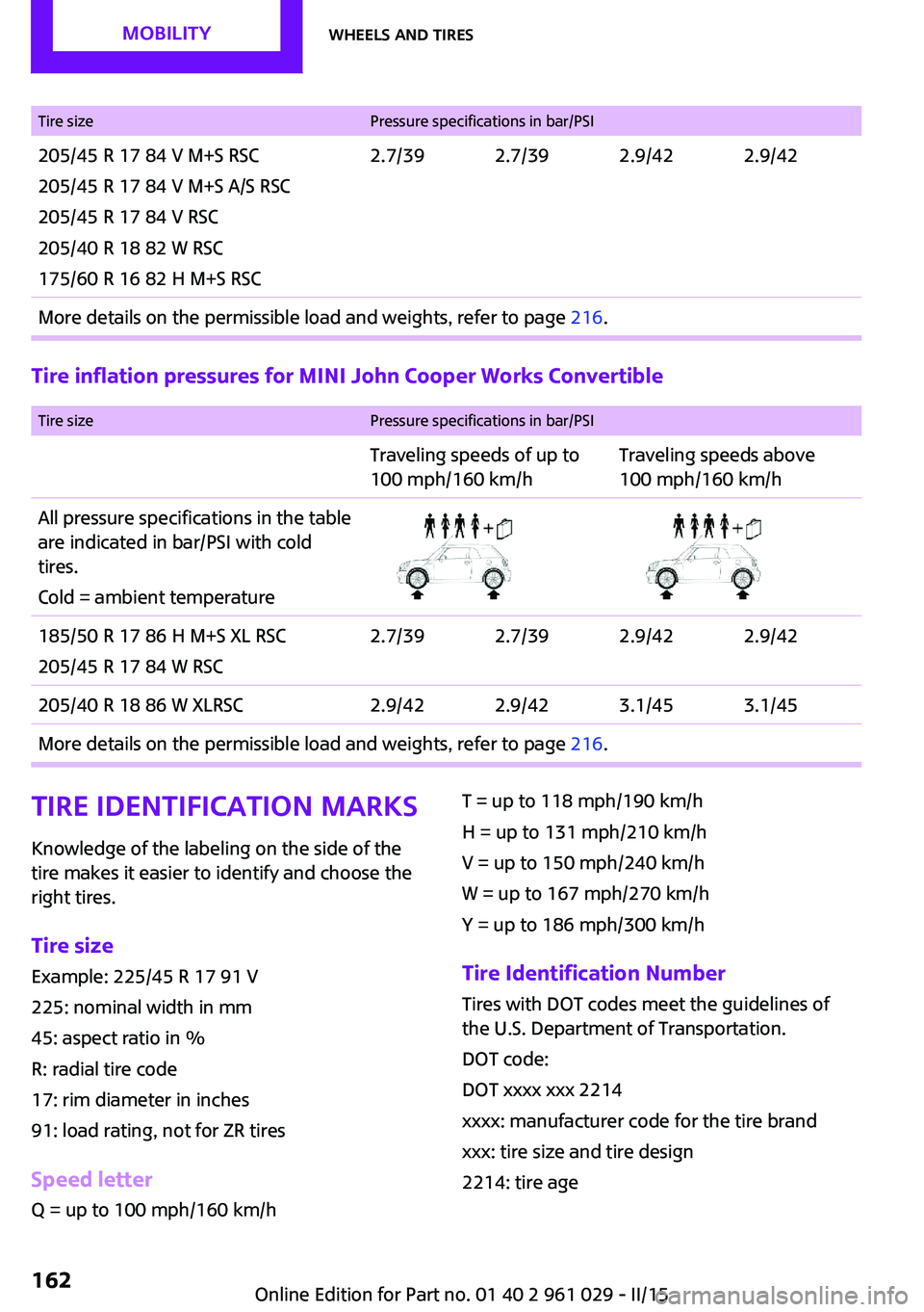
Tire sizePressure specifications in bar/PSI205/45 R 17 84 V M+S RSC
205/45 R 17 84 V M+S A/S RSC
205/45 R 17 84 V RSC
205/40 R 18 82 W RSC
175/60 R 16 82 H M+S RSC2.7/392.7/392.9/422.9/42More details on the permissible load and weights, refer to page 216.
Tire inflation pressures for MINI John Cooper Works Convertible
Tire sizePressure specifications in bar/PSITraveling speeds of up to
100 mph/160 km/hTraveling speeds above
100 mph/160 km/hAll pressure specifications in the table
are indicated in bar/PSI with cold
tires.
Cold = ambient temperature185/50 R 17 86 H M+S XL RSC
205/45 R 17 84 W RSC2.7/392.7/392.9/422.9/42205/40 R 18 86 W XLRSC2.9/422.9/423.1/453.1/45More details on the permissible load and weights, refer to page 216.Tire identification marks
Knowledge of the labeling on the side of the tire makes it easier to identify and choose the
right tires.
Tire size Example: 225/45 R 17 91 V
225: nominal width in mm
45: aspect ratio in %
R: radial tire code
17: rim diameter in inches
91: load rating, not for ZR tires
Speed letter Q = up to 100 mph/160 km/hT = up to 118 mph/190 km/h
H = up to 131 mph/210 km/h
V = up to 150 mph/240 km/h
W = up to 167 mph/270 km/h
Y = up to 186 mph/300 km/h
Tire Identification Number Tires with DOT codes meet the guidelines of
the U.S. Department of Transportation.
DOT code:
DOT xxxx xxx 2214
xxxx: manufacturer code for the tire brand
xxx: tire size and tire design
2214: tire ageSeite 162MOBILITYWheels and tires162
Online Edition for Part no. 01 40 2 961 029 - II/15
Page 168 of 231

Maximum speed of winter tires
If the maximum speed of the vehicle is higher
than the permissible speed for the winter tires,
then display a corresponding sign in the field of
vision. You can obtain this sign from the tire
specialist or from your service center.
Maximum speed for winter tires
Do not exceed the maximum speed for
the winter tires; otherwise, tire damage and ac‐
cidents can occur. ◀
Run-flat tires When mounting new tires or changing fromsummer to winter tires or vice versa, use run-
flat tires for your own safety. Also, a compact
wheel is not available in case of a flat tire. Your
service center will be glad to advise you.
Rotating wheels between axles
Different wear patterns occur on the front and
rear axles, depending on the individual condi‐
tions of use.
To ensure even wear on the tires, the wheels
can be rotated between the axles. Your service
center will be glad to advise you.
After changing the tires, check the tire inflation
pressure and correct it if necessary.
Storage Store wheels and tires in a cool, dry place with
as little exposure to light as possible.
Always protect tires against all contact with oil,
grease and fuels.
Do not exceed the maximum tire inflation pres‐
sure indicated on the side wall of the tire.Run-flat tires
Label
The symbol identifying run-flat tires is a circle
with the letters RSC on the sidewall.
Run-flat tires are tires that support themselves
for a limited period of time, and they may also
come with special rims. The sidewall reinforce‐
ment ensures that the tire can continue to be
used to a limited extent if it has lost pressure
and even if it has become completely depres‐
surized.
For continued driving in the event of a flat tire,
refer to page 85.
Correcting a flat tire Safety measures in case of a breakdown
▷Park the vehicle as far as possible
from passing traffic and on solid
ground. Switch on the hazard warn‐
ing system.▷Let the steering wheel lock engage with the
wheels in the straight-ahead position, set
the parking brake, and engage first gear or
reverse, or engage selector lever position P.▷Have all vehicle occupants get out of the
vehicle and ensure that they remain out‐
side the immediate area in a safe place,
such as behind a guardrail.Seite 166MOBILITYWheels and tires166
Online Edition for Part no. 01 40 2 961 029 - II/15
Page 169 of 231

▷If a warning triangle or portable hazard
warning lamp is required, set it up on the
roadside at an appropriate distance from
the rear of the vehicle. Comply with all
safety guidelines and regulations. ◀
The procedure to correct a flat tire depends on
the equipment in the vehicle:
▷Run-flat tires, refer to page 166.▷MINI Mobility System, refer to page 167.▷Wheel change with a compact wheel, refer
to page 184.
MINI Mobility System
Notes
▷Follow the instructions on using the Mobi‐
lity System found on the compressor and
sealant bottle.▷Use of the Mobility System may be ineffec‐
tive if tire damage is greater than approx.
1/8 in/4 mm in size.▷Contact the nearest service center if the tire
cannot be made drivable.▷If possible, do not remove foreign bodies
that have penetrated the tire.▷Pull the speed limit sticker off the sealant
bottle and apply it to the steering wheel.
Sealant and compressor
1Sealant bottle and speed limit sticker2Filling hose
Note the use-by date on the sealant bottle.3Holder for the sealant bottle4Compressor5Connector and cable for the lighter socket/
socket in passenger compartment 106.6Connection hose for connecting the com‐
pressor and sealant bottle or the compres‐
sor and wheel7On/off switch8Pressure gauge for displaying the tire infla‐
tion pressure9Release button for reducing the tire infla‐
tion pressure
The connector, cable, and connecting hose are
stowed in the compressor housing.
Using the Mobility System
To repair a flat tire with the Mobility System,
proceed as follows:
▷Filling the tire with sealant▷Distributing the sealant▷Correcting the tire inflation pressure
Filling the tire with sealant
Adhere to the specified sequence
Adhere to the specified sequence of the
steps; otherwise, sealant may escape under
high pressure. ◀
1.Shake the sealant bottle.2.Pull the connection hose 6 fully out of the
compressor housing and screw it onto the
sealant bottle connection. Ensure that the
connection hose is not kinked.Seite 167Wheels and tiresMOBILITY167
Online Edition for Part no. 01 40 2 961 029 - II/15
Page 170 of 231

3.Insert the sealant bottle into the compres‐
sor housing in a vertical position.4.Unscrew the dust cap off of the valve of the
defective wheel and screw the filling hose 2
of the sealant bottle onto the valve.5.Ensure that the compressor is switched off.6.Insert connector 5 into the lighter socket/
socket in the passenger compartment, refer
to page 106.7.When the engine is running:
Switch on the compressor and let it run for
approx. 3 to 8 minutes to fill sealant into
the tire and achieve a tire inflation pressure
of approx. 1.8 bar/26 psi.
While sealant is being filled, the inflation
pressure may intermittently rise to approx.
5 bar/73 psi. Do not switch off the com‐
pressor in this phase.8.Switch off the compressor.
Do not allow the compressor to run too
long
Do not allow the compressor to run longer than
10 minutes; otherwise, the device will overheat
and may be damaged. ◀
If an air pressure of 1.8 bar/26 psi is not
reached:
1.Unscrew the filling hose 2 from the wheel
and drive forward and back approx.
33 ft/10 m to evenly distribute the sealant
in the tire.2.Inflate the tire again using the compressor.If the inflation pressure of 1.8 bar/26 psi is still
not reached, the tire is too heavily damaged.
Contact the nearest service center.
Stowing the Mobility System1.Unscrew the filling hose 2 of the sealant
bottle from the wheel.2.Unscrew the compressor connection hose 6
from the sealant bottle.3.Connect the filling hose 2 of the sealant
bottle with the free connector on the seal‐
ant bottle.
This prevents left-over sealant from escap‐
ing from the bottle.4.Wrap the empty sealant bottle in suitable
material to avoid dirtying the cargo area.5.Stow the Mobility System back in the vehi‐
cle.
Distributing the sealant
Drive approx. 3.1 miles/5 km to evenly distrib‐
ute the sealant.
Do not exceed a speed of 50 mph/80 km/h. If
possible, do not drop below a speed of
10 mph/20 km/h.
Correcting the tire inflation pressure
1.After driving approx. 3.1 miles/5 km, or
about 10 minutes, stop in a suitable loca‐
tion.2.Screw the connection hose 6 of the com‐
pressor directly onto the tire valve.3.Insert the connector 5 into the power
socket in the passenger compartment.4.Correct the tire inflation pressure to
1.8 bar/26 psi. When the engine is running:▷To increase the inflation pressure:
switch on the compressor. To check the
currently set inflation pressure, switch
off the compressor.▷To reduce the inflation pressure: press
the release button 9.Seite 168MOBILITYWheels and tires168
Online Edition for Part no. 01 40 2 961 029 - II/15
Page 171 of 231

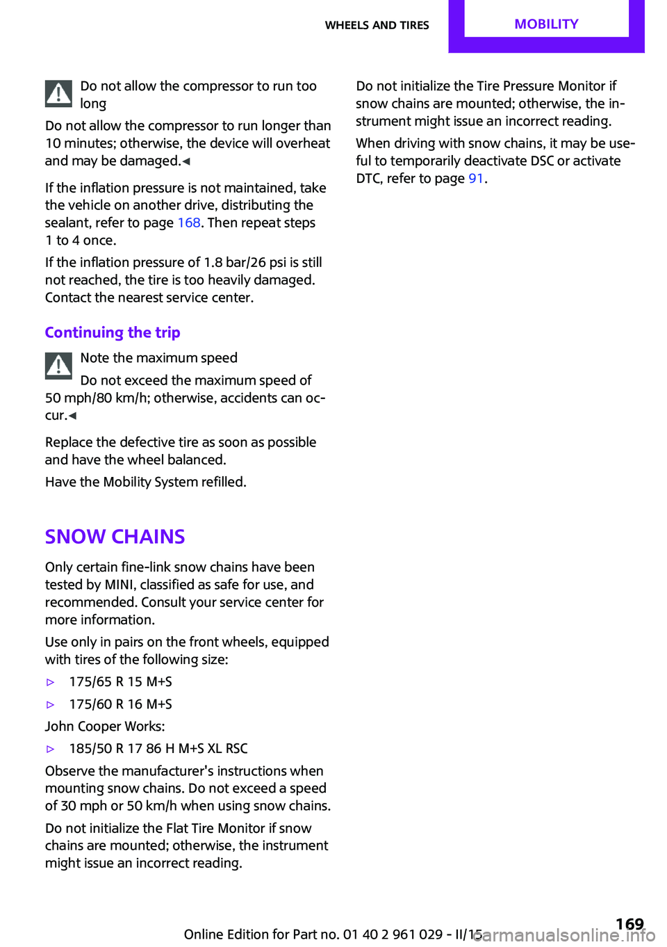
Do not allow the compressor to run too
long
Do not allow the compressor to run longer than
10 minutes; otherwise, the device will overheat
and may be damaged. ◀
If the inflation pressure is not maintained, take
the vehicle on another drive, distributing the
sealant, refer to page 168. Then repeat steps
1 to 4 once.
If the inflation pressure of 1.8 bar/26 psi is still
not reached, the tire is too heavily damaged.
Contact the nearest service center.
Continuing the trip Note the maximum speed
Do not exceed the maximum speed of
50 mph/80 km/h; otherwise, accidents can oc‐
cur. ◀
Replace the defective tire as soon as possible
and have the wheel balanced.
Have the Mobility System refilled.
Snow chains
Only certain fine-link snow chains have been
tested by MINI, classified as safe for use, and
recommended. Consult your service center for more information.
Use only in pairs on the front wheels, equipped
with tires of the following size:▷175/65 R 15 M+S▷175/60 R 16 M+S
John Cooper Works:
▷185/50 R 17 86 H M+S XL RSC
Observe the manufacturer's instructions when
mounting snow chains. Do not exceed a speed
of 30 mph or 50 km/h when using snow chains.
Do not initialize the Flat Tire Monitor if snow
chains are mounted; otherwise, the instrument
might issue an incorrect reading.
Do not initialize the Tire Pressure Monitor if
snow chains are mounted; otherwise, the in‐
strument might issue an incorrect reading.
When driving with snow chains, it may be use‐
ful to temporarily deactivate DSC or activate
DTC, refer to page 91.Seite 169Wheels and tiresMOBILITY169
Online Edition for Part no. 01 40 2 961 029 - II/15
Page 188 of 231

driving characteristics could result, for example
reduced track stability on braking, extended
braking distance, and altered self-steering
characteristics in the limit range. In conjunction
with winter tires, these characteristics are more
pronounced. ◀
Only mount one compact wheel
Only one compact wheel may be
mounted. Restore the wheels and tires to their
original size as quickly as possible. Failure to do
so is a safety risk. ◀
Check the tire inflation pressure at the next op‐
portunity and correct it if necessary. Replace
the defective tire as soon as possible and have
the new wheel balanced.
Preparing wheel change
Observe the safety precautions regarding flat
tires, refer to page 166.
Additional safety precautions in the event
of a wheel change
Change the wheel only on a level, firm surface
which is not slippery.
The vehicle or the jack could slip to the side if
you attempt to raise the vehicle on a soft or
slippery surface, snow, ice, tiles, etc. Do not use
a wooden block or similar object as a support
base for the jack, as this would prevent it from
extending to its full support height and reduce
its load-carrying capacity.
To avoid serious or fatal injury: never lie under
the vehicle, and never start the engine while it
is supported by the jack. ◀1.Place the folding wheel chock behind the
front wheel of the other vehicle side; if the
vehicle is on an incline, place it in front of
this wheel. If the vehicle is parked on a
steep incline, additionally secure the vehi‐
cle against rolling.2.Expose the lug bolts if necessary.3.Loosen the lug bolts a half turn.Jacking up vehicle
The vehicle jack is designed for changing
wheels only.
The vehicle jack is designed for changing
wheels only. Do not attempt to raise another
vehicle model with it or to raise any load of any
kind. To do so could cause accidents and per‐
sonal injury. ◀
1.Position the vehicle jack at the jacking point
closest to the wheel.
The entire surface of the jack base must
rest on the ground vertically beneath the
jacking point.2.Guide the jack head into the rectangular re‐
cess of the jacking point when cranking up.3.Jack the vehicle up until the wheel you are
changing is raised from the ground.
Mounting the compact wheel
1.Unscrew the lug bolts and remove the
wheel.2.Remove accumulations of mud or dirt from
the mounting surfaces of the wheel and
hub. Also clean the lug bolts.Seite 186MOBILITYReplacing components186
Online Edition for Part no. 01 40 2 961 029 - II/15
Page 209 of 231

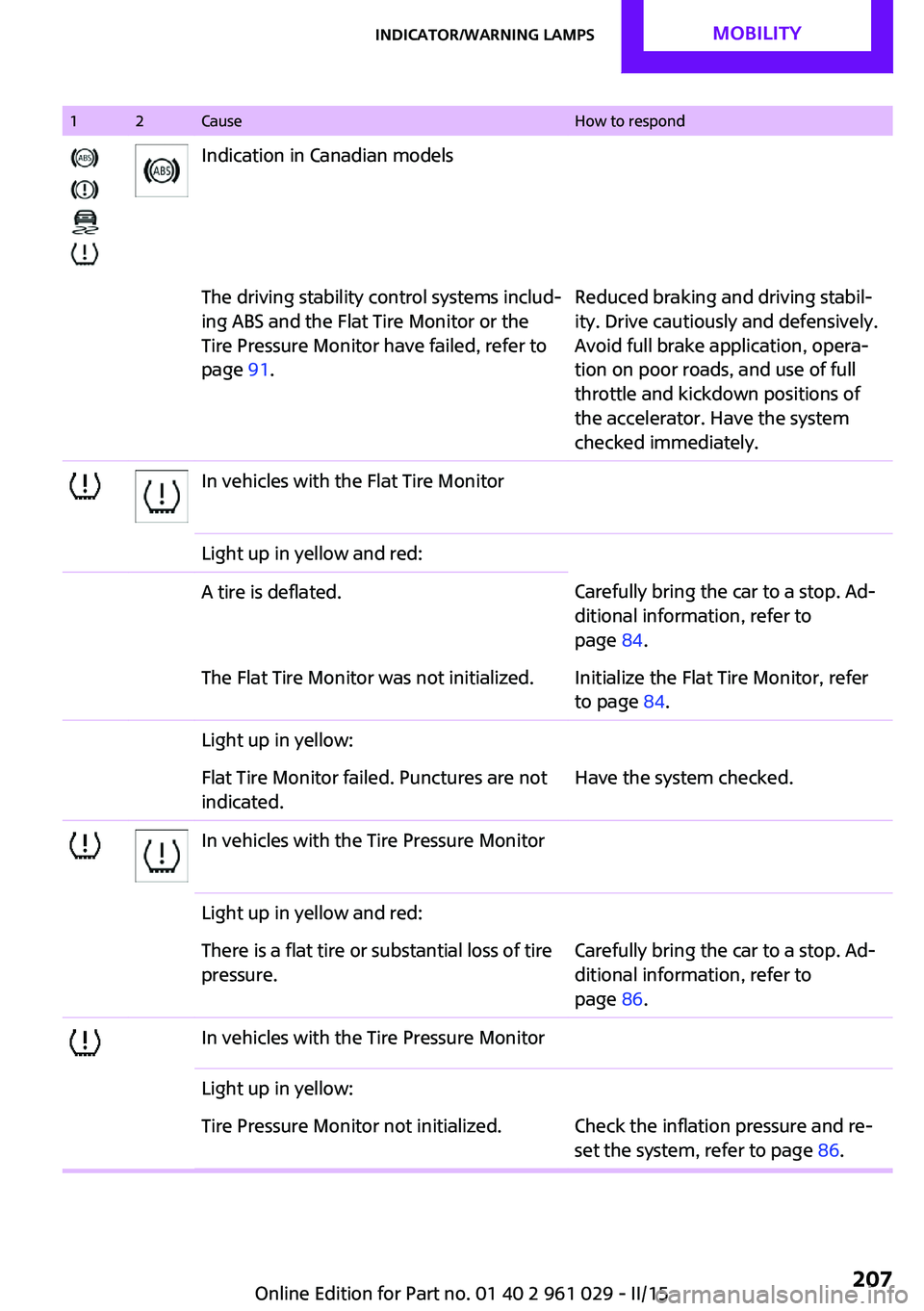
12CauseHow to respondIndication in Canadian modelsThe driving stability control systems includ‐
ing ABS and the Flat Tire Monitor or the
Tire Pressure Monitor have failed, refer to
page 91.Reduced braking and driving stabil‐
ity. Drive cautiously and defensively.
Avoid full brake application, opera‐
tion on poor roads, and use of full
throttle and kickdown positions of
the accelerator. Have the system
checked immediately.In vehicles with the Flat Tire MonitorLight up in yellow and red:A tire is deflated.Carefully bring the car to a stop. Ad‐
ditional information, refer to
page 84.The Flat Tire Monitor was not initialized.Initialize the Flat Tire Monitor, refer
to page 84.Light up in yellow:Flat Tire Monitor failed. Punctures are not
indicated.Have the system checked.In vehicles with the Tire Pressure MonitorLight up in yellow and red:There is a flat tire or substantial loss of tire
pressure.Carefully bring the car to a stop. Ad‐
ditional information, refer to
page 86.In vehicles with the Tire Pressure MonitorLight up in yellow:Tire Pressure Monitor not initialized.Check the inflation pressure and re‐
set the system, refer to page 86.Seite 207Indicator/warning lampsMOBILITY207
Online Edition for Part no. 01 40 2 961 029 - II/15
Page 224 of 231

Headlamps, care 195
Headlight control, auto‐ matic 75
Headlight courtesy delay fea‐ ture 77
Headlight flasher 59
Headlights 75
Headlights, cleaning, washer fluid 62
Head restraints 48
Head restraints, adjusting the height 48
Head restraints, removing 48
Heatable rear window, air conditioner 100
Heatable windshield 103
Heating, rear window with au‐ tomatic climate control 103
Heating, seats 47
Heating, windshield 103
Height adjustment, seats 45
High-beams 76
High beams, bulb replace‐ ment 180
Hill drive-off assistant 93
Hills 116
Holder for remote control, re‐ fer to Ignition lock 56
Homepage 6
Hood 171
Hood, closing 171
Hood, opening 171
Hood, unlocking 171
Horn 12
Hydraulic brake assistant 91
I
Ice warning, refer to External temperature warning 66
Icy roads, refer to External temperature warning 66
Identification marks, run-flat tires 166
Identification marks, tires 162
Ignition 57 Ignition key position 1, refer
to Radio ready state 56
Ignition key position 2, refer to Ignition on 57
Ignition key, refer to Remote control with integrated
key 20
Ignition lock 56
Ignition, switched off 57
Ignition, switched on 57
Indicator and warning lamps, overview 199
Indicator and warning lamps, Tire Pressure Monitor
TPM 87
Indicator and warning lights 15
Individual air distribution 100
Inflation pressure monitor, re‐ fer to Flat Tire Monitor 84
Inflation pressure monitor, re‐ fer to Tire Pressure Monitor
TPM 86
Inflation pressure, refer to Tire inflation pressure 156
Initializing, Flat Tire Monitor FTM 84
Instrument cluster, refer to Displays 14
Instrument lighting 78
Instruments, refer to Cock‐ pit 12
Integrated key 20
Interior lights 79
Interior lights, remote con‐ trol 24
Interior mirror 50
Interior motion sensor 32
Interior temperature, setting, air conditioner 99
Interior temperature, setting, automatic climate con‐
trol 101
Internet page 6 J
Jump-starting 189
K
Keyless Go, refer to Comfort Access 29
Keyless opening and closing, refer to Comfort Access 29
Key Memory, refer to Personal Profile 21
Key, refer to Remote control with integrated key 20
Kickdown, Steptronic trans‐ mission 64
Knocking control 154
L Lamp and bulb replacement, bulb replacement 178
Lamp, replacing, refer to Lamp and bulb replace‐
ment 178
Lamps 75
Lamps, automatic headlight control 75
Lap-and-shoulder belt, refer to Safety belts 47
LATCH child restraint fixing system 53
Leather, care 196
Leather care 196
LEDs, light-emitting di‐ odes 179
License plate light, bulb re‐ placement 182
Light-alloy wheels, care 197
Light-emitting diodes, LEDs 179
Lighter, socket 106
Lighting, instruments 78
Lighting, lamp and bulb re‐ placement 178 Seite 222REFERENCEEverything from A to Z222
Online Edition for Part no. 01 40 2 961 029 - II/15