2015 MINI 5 door fog light
[x] Cancel search: fog lightPage 112 of 248
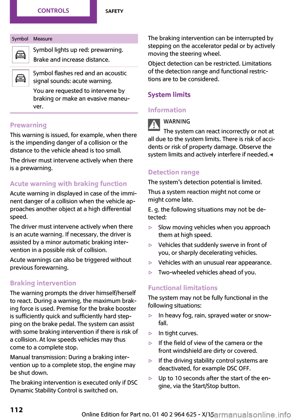
SymbolMeasureSymbol lights up red: prewarning.
Brake and increase distance.Symbol flashes red and an acoustic
signal sounds: acute warning.
You are requested to intervene by
braking or make an evasive maneu‐
ver.
Prewarning
This warning is issued, for example, when there
is the impending danger of a collision or the
distance to the vehicle ahead is too small.
The driver must intervene actively when there is a prewarning.
Acute warning with braking function
Acute warning in displayed in case of the immi‐
nent danger of a collision when the vehicle ap‐
proaches another object at a high differential
speed.
The driver must intervene actively when there
is an acute warning. If necessary, the driver is
assisted by a minor automatic braking inter‐
vention in a possible risk of collision.
Acute warnings can also be triggered without
previous forewarning.
Braking intervention The warning prompts the driver himself/herself
to react. During a warning, the maximum brak‐
ing force is used. Premise for the brake booster
is sufficiently quick and sufficiently hard step‐
ping on the brake pedal. The system can assist
with some braking intervention if there is risk of
a collision. At low speeds vehicles may thus
come to a complete stop.
Manual transmission: During a braking inter‐
vention up to a complete stop, the engine may
be shut down.
The braking intervention is executed only if DSC
Dynamic Stability Control is switched on.
The braking intervention can be interrupted by
stepping on the accelerator pedal or by actively
moving the steering wheel.
Object detection can be restricted. Limitations
of the detection range and functional restric‐
tions are to be considered.
System limits
Information WARNING
The system can react incorrectly or not at
all due to the system limits. There is risk of acci‐
dents or risk of property damage. Observe the
system limits and actively interfere if needed. ◀
Detection range The system's detection potential is limited.
Thus a system reaction might not come or
might come late.
E. g. the following situations may not be de‐
tected:▷Slow moving vehicles when you approach
them at high speed.▷Vehicles that suddenly swerve in front of
you, or sharply decelerating vehicles.▷Vehicles with an unusual rear appearance.▷Two-wheeled vehicles ahead of you.
Functional limitations
The system may not be fully functional in the
following situations:
▷In heavy fog, rain, sprayed water or snow‐
fall.▷In tight curves.▷If the field of view of the camera or the
front windshield are dirty or covered.▷If the driving stability control systems are
deactivated, for example DSC OFF.▷Up to 10 seconds after the start of the en‐
gine, via the Start/Stop button.Seite 112CONTROLSSafety112
Online Edition for Part no. 01 40 2 964 625 - X/15
Page 115 of 248
The braking intervention can be interrupted by
stepping on the accelerator pedal or by actively
moving the steering wheel.
Object detection can be restricted. Limitations
of the detection range and functional restric‐
tions are to be considered.
System limits
Information WARNING
The system can react incorrectly or not at
all due to the system limits. There is risk of acci‐
dents or risk of property damage. Observe the
system limits and actively interfere if needed. ◀
Detection range
The detection potential of the camera is lim‐
ited.
Thus a warning might not be issued or be is‐
sued late.
E. g. the following situations may not be de‐
tected:▷Partially covered pedestrians.▷Pedestrians that are not detected as such
because of the viewing angle or contour.▷Pedestrians outside of the detection range.▷Pedestrians having a body size less than
32 inches/80 cm.
Functional limitations
The system may not be fully functional or may
not be available in the following situations:
▷In heavy fog, rain, sprayed water or snow‐
fall.▷In tight curves.▷If the field of view of the camera or the
front windshield are dirty or covered.▷If the driving stability control systems are
deactivated, for example DSC OFF.▷Up to 10 seconds after the start of the en‐
gine, via the Start/Stop button.▷During calibration of the camera immedi‐
ately after vehicle delivery.▷If there are constant blinding effects be‐
cause of oncoming light, e. g., from the sun
low in the sky.▷When it is dark outside.
Brake force display
The concept
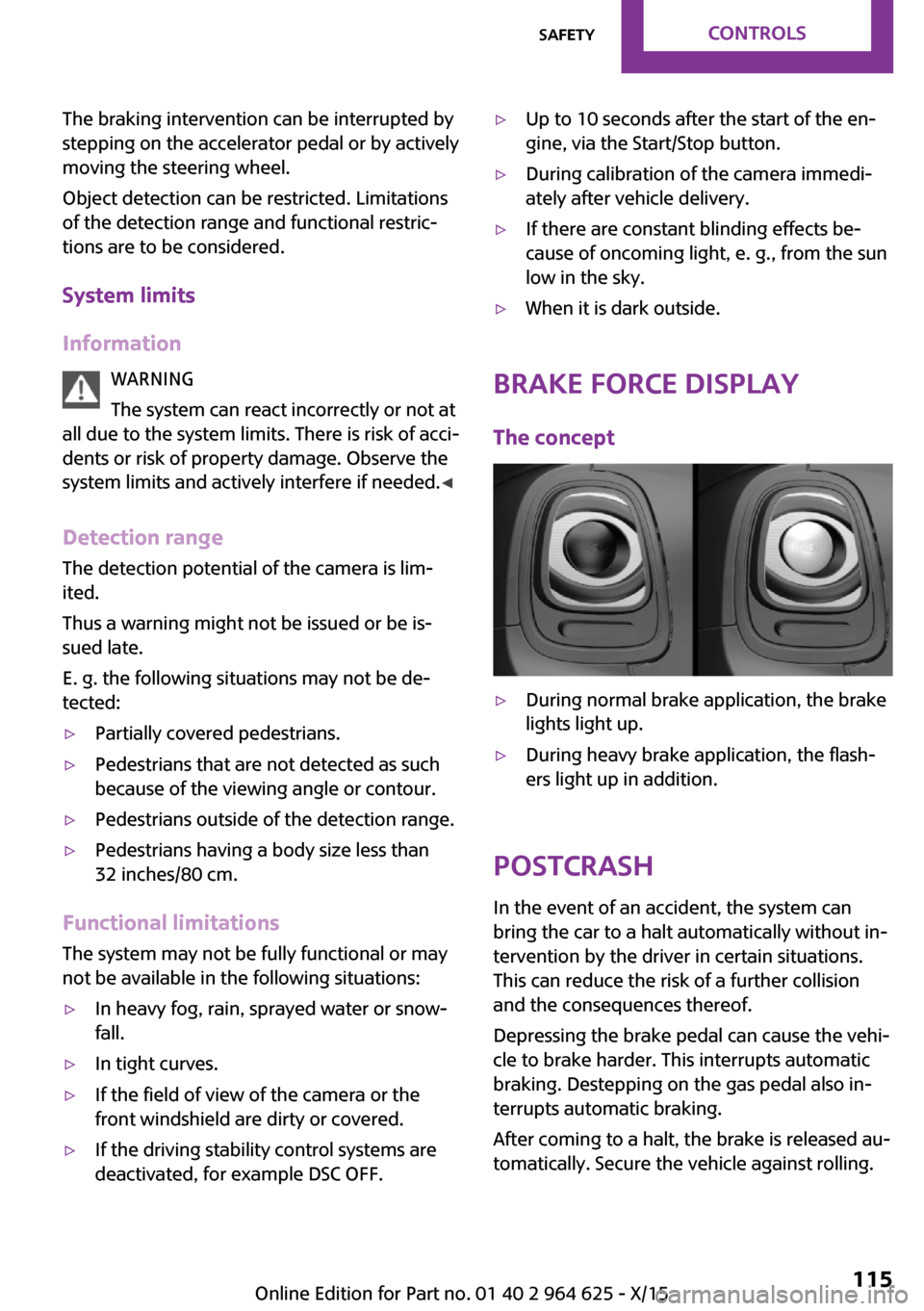
▷During normal brake application, the brake
lights light up.▷During heavy brake application, the flash‐
ers light up in addition.
PostCrash
In the event of an accident, the system can
bring the car to a halt automatically without in‐
tervention by the driver in certain situations.
This can reduce the risk of a further collision
and the consequences thereof.
Depressing the brake pedal can cause the vehi‐
cle to brake harder. This interrupts automatic
braking. Destepping on the gas pedal also in‐
terrupts automatic braking.
After coming to a halt, the brake is released au‐
tomatically. Secure the vehicle against rolling.
Seite 115SafetyCONTROLS115
Online Edition for Part no. 01 40 2 964 625 - X/15
Page 125 of 248
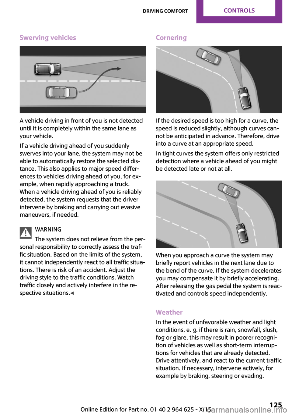
Swerving vehicles
A vehicle driving in front of you is not detected
until it is completely within the same lane as
your vehicle.
If a vehicle driving ahead of you suddenly
swerves into your lane, the system may not be
able to automatically restore the selected dis‐
tance. This also applies to major speed differ‐
ences to vehicles driving ahead of you, for ex‐
ample, when rapidly approaching a truck.
When a vehicle driving ahead of you is reliably
detected, the system requests that the driver
intervene by braking and carrying out evasive
maneuvers, if needed.
WARNING
The system does not relieve from the per‐
sonal responsibility to correctly assess the traf‐
fic situation. Based on the limits of the system,
it cannot independently react to all traffic situa‐
tions. There is risk of an accident. Adjust the
driving style to the traffic conditions. Watch
traffic closely and actively interfere in the re‐
spective situations. ◀
Cornering
If the desired speed is too high for a curve, the
speed is reduced slightly, although curves can‐
not be anticipated in advance. Therefore, drive
into a curve at an appropriate speed.
In tight curves the system offers only restricted
detection where a vehicle ahead of you might
be detected late or not at all.
When you approach a curve the system may
briefly report vehicles in the next lane due to
the bend of the curve. If the system decelerates
you may compensate it by briefly accelerating.
After releasing the gas pedal the system is reac‐
tivated and controls speed independently.
Weather
In the event of unfavorable weather and light conditions, e. g. if there is rain, snowfall, slush,
fog or glare, this may result in poorer recogni‐
tion of vehicles as well as short-term interrup‐
tions for vehicles that are already detected.
Drive attentively, and react to the current traffic
situation. If necessary, intervene actively, for
example by braking, steering or evading.
Seite 125Driving comfortCONTROLS125
Online Edition for Part no. 01 40 2 964 625 - X/15
Page 126 of 248
MalfunctionA Check Control message is displayed if the sys‐
tem fails or was automatically deactivated.
The system may not be fully functional in the
following situations:▷When an object was not correctly detected.▷In heavy fog, rain, sprayed water or snow‐
fall.▷In tight curves.▷If the field of view of the camera or the
front windshield are dirty or covered.▷When driving toward bright lights.▷Up to 20 seconds after the start of the en‐
gine, via the Start/Stop button.▷During calibration of the camera immedi‐
ately after vehicle delivery.
Cruise control
The concept
The system is functional at speeds beginning at
approx. 20 mph/30 km/h.
It maintains the speed that was set using the
control elements on the steering wheel.
The system brakes on downhill gradients if en‐
gine braking is insufficient.
Information WARNING
The system does not relieve from the per‐
sonal responsibility to correctly assess the traf‐
fic situation. Based on the limits of the system,
it cannot independently react to all traffic situa‐
tions. There is risk of an accident. Adjust the
driving style to the traffic conditions. Watch
traffic closely and actively interfere in the re‐
spective situations. ◀
WARNING
The use of the system can lead to an in‐
creased risk of accidents in the following situa‐
tions:▷On winding roads.▷In heavy traffic.▷On slippery roads, in fog, snow or rain, or
on a loose road surface.
There is risk of accidents or risk of property
damage. Only use the system if driving at con‐
stant speed is possible. ◀
General information Depending on the driving program, refer to
page 118, set, the characteristics of the cruise
control in particular areas can change.
Overview
Buttons on the steering wheel
Press buttonFunctionCruise control on/offStore speedPausing cruise control
Continue cruise control with the
last settingIncreasing, maintaining or storing
the speedReducing, maintaining or storing
the speed
Controls
Switching on Press button on the steering wheel.
Seite 126CONTROLSDriving comfort126
Online Edition for Part no. 01 40 2 964 625 - X/15
Page 165 of 248
Roof racks are available as special accessories.Securing
Follow the installation instructions of the roof
rack.
Loading
Because roof racks raise the vehicle's center of
gravity when loaded, they have a major effect
on vehicle handling and steering response.
Therefore, note the following when loading and
driving:▷Do not exceed the approved roof/axle
loads and the approved gross vehicle
weight.▷Be sure that adequate clearance is main‐
tained for tilting and opening the glass sun‐
roof.▷Distribute the roof load uniformly.▷The roof load should not extend past the
loading area.▷Always place the heaviest pieces on the
bottom.▷Secure the roof luggage firmly, e.g., tie with
ratchet straps.▷Do not let objects project into the opening
path of the tailgate.▷Drive cautiously and avoid sudden acceler‐
ation and braking maneuvers. Take corners
gently.
Rear luggage rack
General information Installation only possible with rear luggage rack
preparation.
Rear racks are available as special accessories.
Information Follow the installation instructions of the rear
luggage rack.
Drive cautiously and avoid sudden acceleration
and braking maneuvers. Take corners gently.
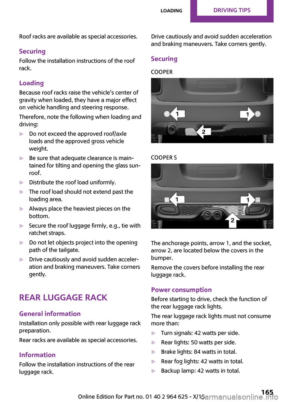
SecuringCOOPERCOOPER S
The anchorage points, arrow 1, and the socket,
arrow 2, are located below the covers in the
bumper.
Remove the covers before installing the rear
luggage rack.
Power consumption
Before starting to drive, check the function of
the rear luggage rack lights.
The rear luggage rack lights must not consume
more than:
▷Turn signals: 42 watts per side.▷Rear lights: 50 watts per side.▷Brake lights: 84 watts in total.▷Rear fog lights: 42 watts in total.▷Backup lamp: 42 watts in total.Seite 165LoadingDRIVING TIPS165
Online Edition for Part no. 01 40 2 964 625 - X/15
Page 206 of 248
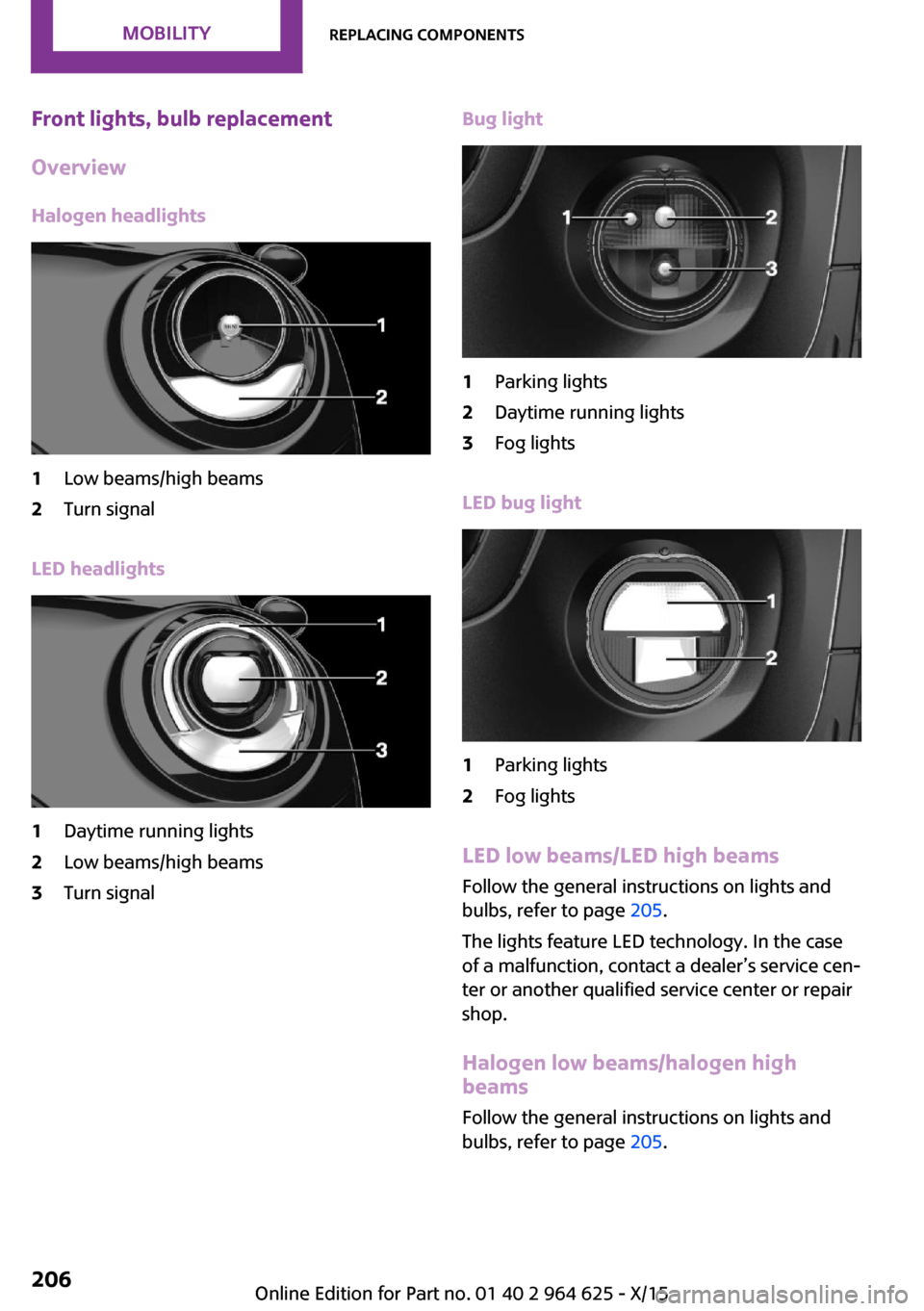
Front lights, bulb replacement
Overview
Halogen headlights1Low beams/high beams2Turn signal
LED headlights
1Daytime running lights2Low beams/high beams3Turn signalBug light1Parking lights2Daytime running lights3Fog lights
LED bug light
1Parking lights2Fog lights
LED low beams/LED high beams Follow the general instructions on lights and
bulbs, refer to page 205.
The lights feature LED technology. In the case
of a malfunction, contact a dealer’s service cen‐
ter or another qualified service center or repair
shop.
Halogen low beams/halogen high
beams
Follow the general instructions on lights and
bulbs, refer to page 205.
Seite 206MOBILITYReplacing components206
Online Edition for Part no. 01 40 2 964 625 - X/15
Page 208 of 248
LED parking lights/LED fog lightsFollow the general instructions on lights and
bulbs, refer to page 205.
The lights feature LED technology. In the case
of a malfunction, contact a dealer’s service cen‐
ter or another qualified service center or repair
shop.
Parking lights/fog lights/daytime
running lights
Follow the general instructions on lights and
bulbs, refer to page 205.
Bulbs:▷Parking lights for halogen headlights: W5W
Parking lights for LED headlights: W5W NBV▷Daytime running light: PSX24W▷Fog lamp: H8
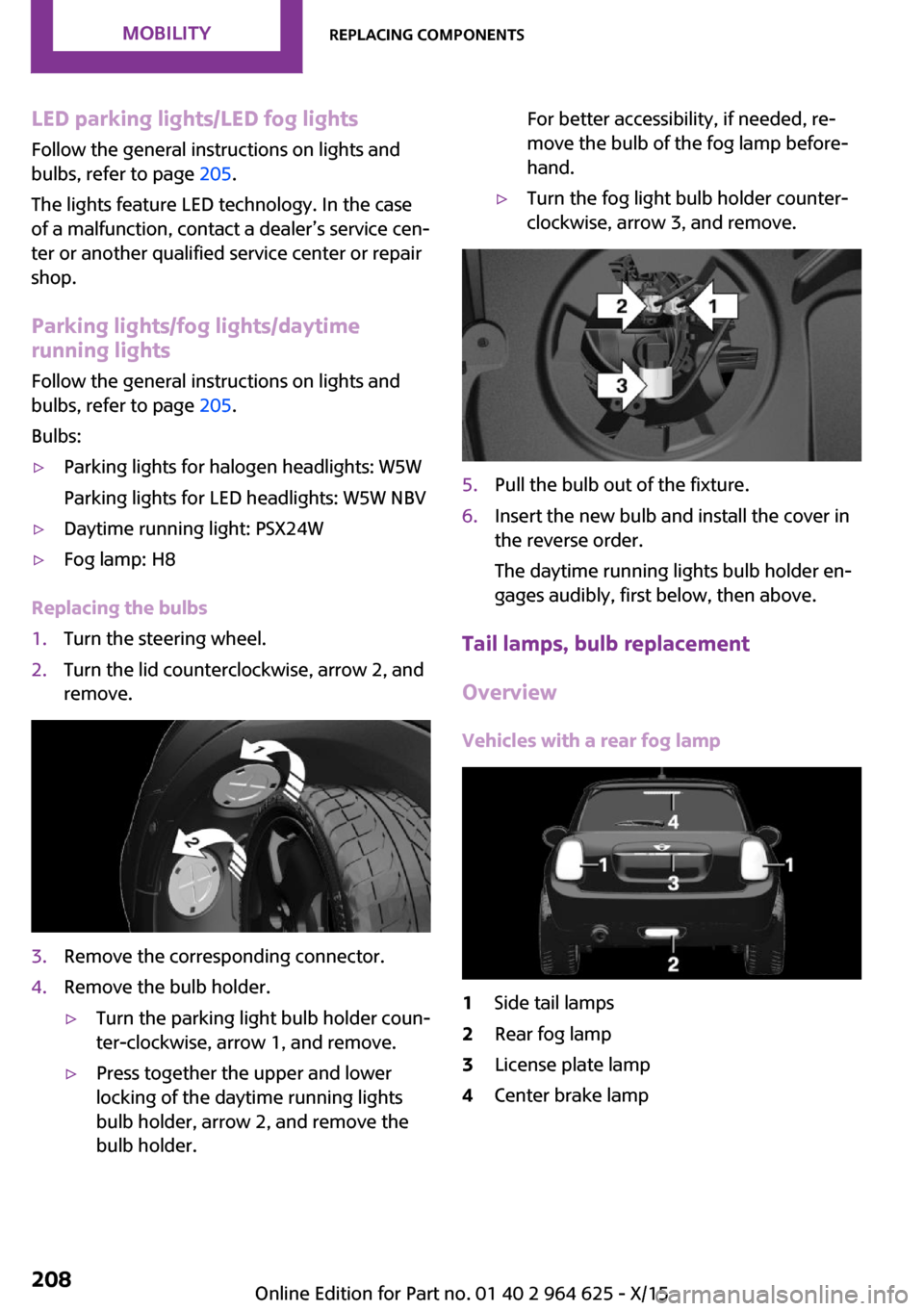
Replacing the bulbs
1.Turn the steering wheel.2.Turn the lid counterclockwise, arrow 2, and
remove.3.Remove the corresponding connector.4.Remove the bulb holder.▷Turn the parking light bulb holder coun‐
ter-clockwise, arrow 1, and remove.▷Press together the upper and lower
locking of the daytime running lights
bulb holder, arrow 2, and remove the
bulb holder.For better accessibility, if needed, re‐
move the bulb of the fog lamp before‐
hand.▷Turn the fog light bulb holder counter-
clockwise, arrow 3, and remove.5.Pull the bulb out of the fixture.6.Insert the new bulb and install the cover in
the reverse order.
The daytime running lights bulb holder en‐
gages audibly, first below, then above.
Tail lamps, bulb replacement
Overview
Vehicles with a rear fog lamp
1Side tail lamps2Rear fog lamp3License plate lamp4Center brake lampSeite 208MOBILITYReplacing components208
Online Edition for Part no. 01 40 2 964 625 - X/15
Page 209 of 248
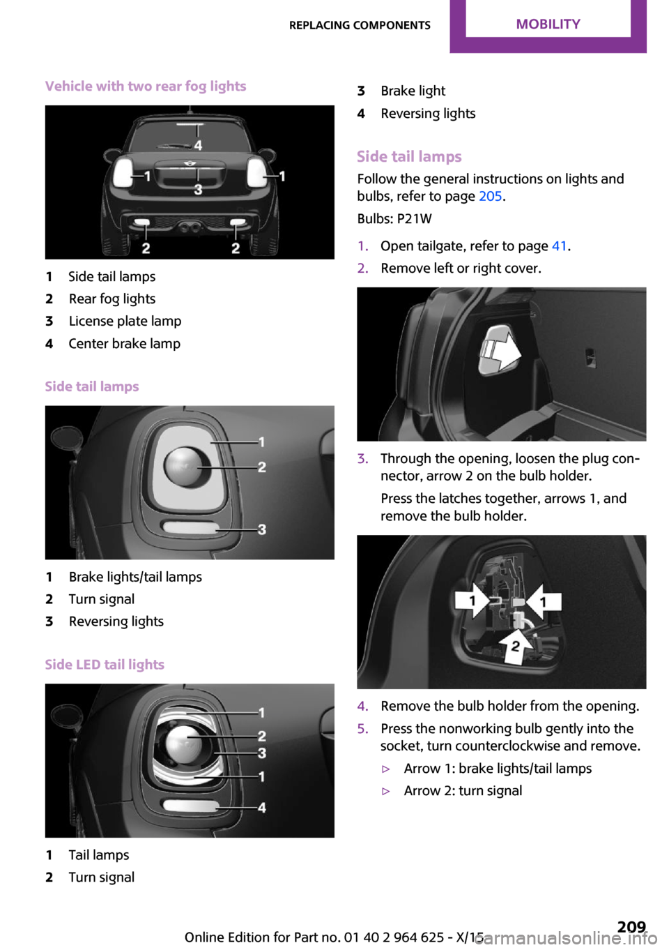
Vehicle with two rear fog lights1Side tail lamps2Rear fog lights3License plate lamp4Center brake lamp
Side tail lamps
1Brake lights/tail lamps2Turn signal3Reversing lights
Side LED tail lights
1Tail lamps2Turn signal3Brake light4Reversing lights
Side tail lampsFollow the general instructions on lights and
bulbs, refer to page 205.
Bulbs: P21W
1.Open tailgate, refer to page 41.2.Remove left or right cover.3.Through the opening, loosen the plug con‐
nector, arrow 2 on the bulb holder.
Press the latches together, arrows 1, and
remove the bulb holder.4.Remove the bulb holder from the opening.5.Press the nonworking bulb gently into the
socket, turn counterclockwise and remove.▷Arrow 1: brake lights/tail lamps▷Arrow 2: turn signalSeite 209Replacing componentsMOBILITY209
Online Edition for Part no. 01 40 2 964 625 - X/15