2015 MERCEDES-BENZ SLS AMG GT COUPE brake
[x] Cancel search: brakePage 271 of 290
GVWR (Gross Vehicl
eWeight Rating)
The GVWR is the maximu mpermitted gross
weight of the fullyl oaded vehicle (weight of
the vehicle including all accessories, occu-
pants, fuel,l uggage and the drawbar nose-
weight if applicable).T he gross vehicle weight
rating is specified on the vehicle identification plate on the B-pilla ronthe driver's side.
Maximum loaded vehicle weight
The maximu mweight is the sum of the curb
weight of the vehicle ,the weight of the acces-
sories ,the total loadl imitand the weight of
the optional equipment installed at the fac-
tory.
Kilopascal (kPa)
Metric unit for tire pressure. 6.9 kPa is the
equivalent of 1psi.A nother unit for tire pres-
sure is bar. There are 100 kilopascals (kPa) to
1b ar.
Load index
In addition to the load-bearing index, the load index may alsobei mprinted on the sidewallof
the tire. This specifies the load-bearing capa-
city more precisely.
Curb weight
The weight of avehicle with standard equip-
ment including the maximu mcapacity of fuel,
oil and coolant. It alsoi ncludes the air-condi-
tioning system and optional equipment if
these are installed in the vehicle ,but does not
includ epassengers or luggage.
Maximum load rating
The maximu mloadr ating in kilograms or
pounds is the maximu mweight for which a
tire is approved.
Maximum permissible tire pressure
Maximu mpermissibl etire pressure for one
tire.
Maximum load on one tire
Maximu mloadono ne tire. This is calculated
by dividing the maximu maxle loadofo ne axle
by two. PSI (pounds per square inch)
As
tandard unit of measure for tire pressure.
Aspec tratio
Relationshi pbetwee ntire heigh tand tire
width in percent.
tire pressure
This is pressure inside the tire applying an
outward force to each square inch of the tire's surface. The tire pressure is specified in
pounds per square inch (psi), in kilopascal
(kPa) or in bar. The tire pressure shoul donly
be corrected when the tires are cold. For this,
the vehicle must have been stationary for at
least three hours or not have traveled more
than 1.6 km (1 mile)int his time.
Tire pressure of coldt ires
The tires are cold:
R if the vehicle has been parked without
direct sunlight on the tires for at least three
hours and
R if the vehicle has not been driven more than
1m ile (1.6 km)
Tread
The part of the tire that comes into contact
with the road.
Bead
The tire beade nsures that the tire sits
securel yonthe wheel. There are severa lsteel
wiresint he beadtop revent the tire from
coming loose from the wheelr im.
Sidewall
The part of the tire betwee nthe tread and the
bead.
Weight of optional extras
The combined weight of those optional extras
that weigh more than the replaced standard
part and more than 2.3 kilograms (5 lbs).
These optional extras, such as high-perform-
ance brakes, level control, aroof rack or a
high-performance battery, are not included in Alla
bout wheels and tires
269Wheelsand tires Z
Page 272 of 290
the curb weight and the weight of the acces-
sories.
TIN (Tire Identificatio nNumber)
This is auniqu eide ntifier which can be used
by atirem anufacturer to identify tires ,for
exampl efor ap roduct recall, and thu side ntify
the purchasers. Th eTIN is made up of the
manufacturer's identity code, tir esize, tire
typ ecodea nd the manufacturing date.
Load bearin gind ex
Th eloa db eari ng index (als oloa dindex) is a
cod etha tcontains the maximum load bearing
capacity of atire.
Traction
Tractio nist he resul toffrictio nbetween the
tires and the roa dsurface.
Treadwea rind icators
This is indicated by narrow bars (treadwear
bars) tha tare distributed ove rthe tir etread. If
the tir etrea disl evel with the bars, the wear
limi tof 1
/ 16 in (1.
6mm) ha sbeenr eached.
Occupant distribution
Th ed istributio nofoccupants in avehicl eat
their designated seating positions.
Tota lloa dl im it
Rated cargo and luggag eloa dp lus68k ilo-
grams (15 0lb) times the vehicle' sdesig nated
seating capacity. Changin
gawheel Flat tire
Th e" Breakdown assistance" section
(Y page 235 )contains information and notes
on ho wtod ealw ithaf latt ire. Rotatin
gthe wheels G
WARNING
Interchanging the front and rea rwheel smay
severel yimpair the driving characteristics if
the wheels or tires have different dimensions. Th ew heel brakes or suspensio ncomponents
ma yalsobed amaged .The re is ariskofa cci-
dent.
Rotate front and rea rwheel sonlyift he wheels
and tires ar eofthe same dimensions.
! On vehicles equipped with
atirep ressure
monitor, electroni ccomponents are
locate dinthe wheel.
Tire-mounting tools shoul dnot be used
nea rthe valve. This could damage the elec-
troni ccomponents.
Onl yhavet ires change dataqualified spe-
cialist workshop.
Alway spayattentio ntothe instructions and
safety note swhenc hanging awheel
( Y page 271).
Th ew earp atterns on the front and rea rtires
differ, depending on the operating conditions.
Rotate the wheels befor eaclear wear pattern
ha sformed on the tires .Front tires typically
wear mor eonthe shoulders and the rea rtires
in the center.
If your vehicle' stirec onfiguration allows ,you
can change the wheels according to the inter-
vals in the tir emanufacturer's warranty book
in your vehicl edocum ents.Ifnow arranty
book is available, the tires shoul dberotated
every 3,000 to 6,000 mile s(5,000 to
10,000 km), or earlie riftirew earrequires .Do
not change the directio nofwheelrotation.
Clea nthe contact surfaces of the whee land
the brake disc thoroughly every tim eawheel
is rotated .Check the tir epressure and reac-
tivate the tir epressure monitor if necessary. Directio
nofrotation
Tires with aspecified directio nofrotation
have additional benefits, e.g .ifthere is arisk 270
Changin
gawheelWheels an dtires
Page 273 of 290
of hydroplaning. You will only gain these ben-
efits if the correc tdirection of rotation is
maintained.
An arrow on the sidewal lofthe tire indicates
its correc tdirection of rotation. Storing wheels
Storew heels that are not being used in acool,
dry and preferably dark place. Protec tthe
tires from oil, grease, gasoline and diesel. Cleaning the wheels
G
WARNING
The water jet from acircular jet nozzle (dirt
blasters) can cause invisible exterior damage to the tires or chassis components. Compo-
nentsd amaged in this way may fail unexpect-
edly. There is arisk of an accident.
Do not use power washers with circular jet
nozzles to clean the vehicle. Have damaged
tires or chassis components replaced imme-
diately. Mounting
awheel
Preparing the vehicle X
Stop the vehicle on solid, non-slippery and
level ground.
X Apply the electric parking brake manually.
X Bring the front wheels into the straight-
ahead position.
X Shift the transmission to position P.
X Switch off the engine.
X Open the driver's door.
The on-board electronics now have status
0.T his is the same as the SmartKey having
been removed.
X Remove Start/Stop button from ignition
lock (Y page 119). X
Take the following object sfrom the left-
hand stowage compartment and the left-
hand stowage space in the trunk:
R lug wrench
R folding wheel chock
R jack
R alignment bolt
X Secure the vehicle to prevent it from rolling
away.
Securing the vehicle to prevent it from
rolling away If your vehicle is equipped with
awheel chock,
it can be found in the vehicle tool kit
(Y page 234).
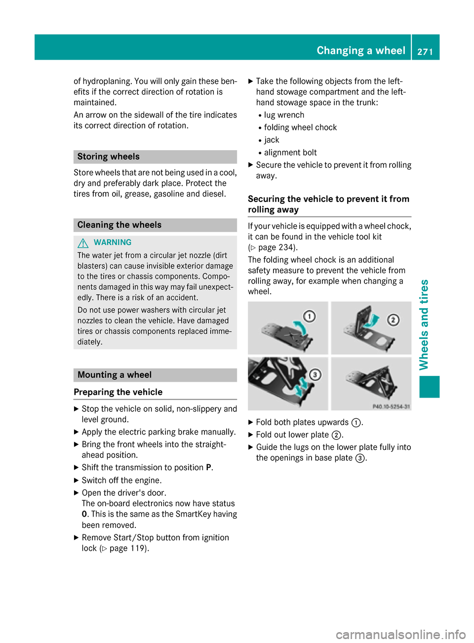
The folding wheel chock is an additional
safety measure to prevent the vehicle from
rolling away,f or example when changing a
wheel. X
Fold both plates upwards 0043.
X Fold out lower plate 0044.
X Guide the lugs on the lower plate fully into
the openings in base plate 0087. Changing
awheel
271Wheels and tires Z
Page 274 of 290
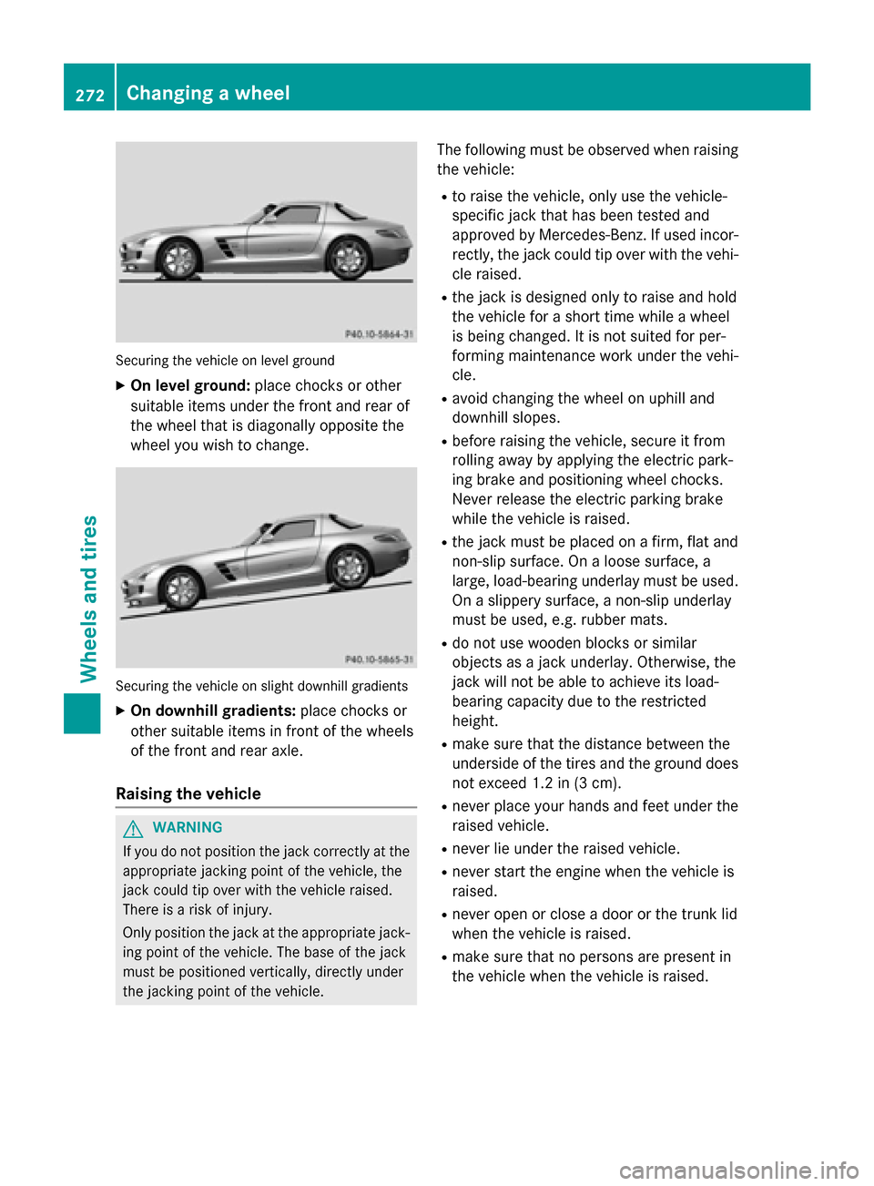
Securing the vehicle on level ground
X On level ground: place chocks or other
suitabl eitem sunder the front and rea rof
the wheel that is diagonall yopposite the
wheel yo uwishtoc hange. Securing the vehicle on slight downhil
lgradients
X On downhill gradients: place chocks or
othe rsuitabl eitem sinf ront of the wheels
of the front and rea raxle.
Raisin gthe vehicle G
WARNING
If yo udon ot position the jack correctly at the
appropriate jacking point of the vehicle ,the
jack could tip ove rwitht he vehicle raised.
There is ariskofi njury.
Only position the jack at the appropriate jack-
ing point of the vehicle .The base of the jack
mus tbep ositioned vertically ,directl yunder
the jacking point of the vehicle. The following mus
tbeo bserve dwhenr aising
the vehicle:
R to raise the vehicle ,only us ethe vehicle-
specifi cjack that ha sbeent ested and
approved by Mercedes-Benz. If used incor-
rectly, the jack could tip ove rwitht he vehi-
cle raised.
R the jack is designe donly to raise and hold
the vehicle for ashort time whil eawheel
is being changed .Itisnot suited for per-
forming maintenance work under the vehi-
cle.
R avoid changing the wheel on uphil land
downhil lslopes.
R before raising the vehicle ,secure it from
rolling away by applying the electri cpark-
ing brake and positioning wheel chocks.
Neve rrelease the electri cparking brake
whil ethe vehicle is raised.
R the jack mus tbep lace donaf irm,flata nd
non-slip surface. On aloose surface, a
large ,load-bearing underlay mus tbeu sed.
On aslippery surface, anon-slip underlay
mus tbeu sed, e.g. rubber mats.
R do not us ewoodenb locks or similar
objects as ajack underlay .Otherwise, the
jack will not be able to achieve its load-
bearing capacity du etothe restricted
height.
R make sure that the distance between the
underside of the tire sand the ground does
not excee d1.2 in (3 cm).
R never place your hands and fee tunder the
raised vehicle.
R never li eunder the raised vehicle.
R never star tthe engine when the vehicle is
raised.
R never ope norclosead oorort he trunk lid
when the vehicle is raised.
R make sure that no persons are present in
the vehicle when the vehicle is raised. 272
Changing
awheelWheels and tires
Page 275 of 290
X
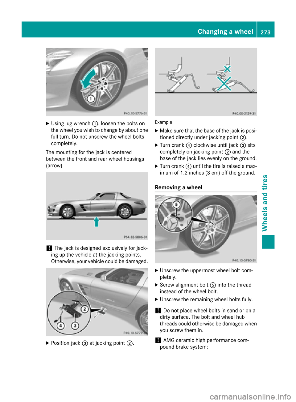
Using lug wrench 0043,loosen the bolts on
the wheel you wish to change by abouto ne
full turn. Do not unscrew the wheel bolts
completely.
The mounting for the jack is centered
between the front and rear wheel housings
(arrow). !
The jack is designed exclusively for jack-
ing up the vehicle at the jacking points.
Otherwise, your vehicle could be damaged. X
Position jack 0087at jacking point 0044. Example
X Make sure that the base of the jack is posi-
tioned directly under jacking point 0044.
X Turn crank 0085clockwise until jack 0087sits
completely on jacking point 0044and the
base of the jack lies evenly on the ground.
X Turn crank 0085until the tire is raised amax-
imum of 1.2 inches (3 cm) off the ground.
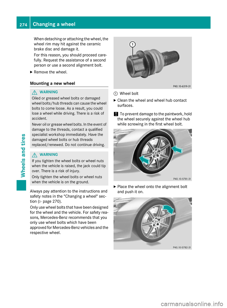
Removing awheel X
Unscrew the uppermost wheel bolt com-
pletely.
X Screw alignment bolt 0083into the thread
instead of the wheel bolt.
X Unscrew the remaining wheel bolts fully.
! Do not place wheel bolts in sand or on a
dirty surface. The bolt and wheel hub
threads could otherwise be damagedw hen
you screw them in.
! AMG ceramic high performance com-
pound brake system: Changing
awheel
273Wheels and tires Z
Page 276 of 290
When detachin
gorattaching the wheel, the
wheel rim may hit against the ceramic
brake disc and damage it.
For this reason, you should proceed care-
fully. Request the assistanc eofasecond
person or use asecon dalignment bolt.
X Remove the wheel.
Mounting anew wheel G
WARNING
Oiled or greased wheel bolts or damaged
wheel bolts/hub threads can cause the wheel bolts to come loose. As aresult, you could
lose awheel while driving. There is arisk of
accident.
Never oil or grease wheel bolts. In the event of damage to the threads, contact aqualified
specialist workshop immediately. Have the
damaged wheel bolts or hub threads
replaced/renewed. Do not continue driving. G
WARNING
If you tighten the wheel bolts or wheel nuts
when the vehicle is raised, the jack could tip
over. There is arisk of injury.
Only tighten the wheel bolts or wheel nuts
when the vehicle is on the ground.
Always pay attention to the instructions and
safety notes in the "Changing awheel" sec-
tion (Y page 270).
Only use wheel bolts that have been designed for the wheel and the vehicle. For safety rea-
sons, Mercedes-Benz recommends that you
only use wheel bolts which have been
approved for Mercedes-Benz vehicles and the
respective wheel. 0043
Wheel bolt
X Clean the wheel and wheel hub contact
surfaces.
! To preven
tdamage to the paintwork ,hold
the wheel securely against the wheel hub
while screwin ginthe first wheel bolt. X
Place the wheel ontot he alignment bolt
and push it on. 274
Changing
awheelWheels and tires
Page 283 of 290
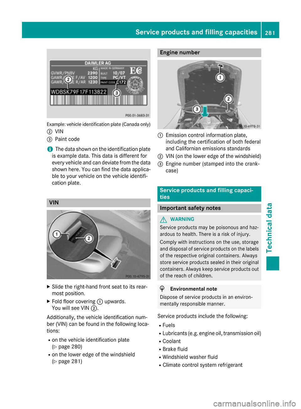
Example: vehicl
eide ntification plate (Canada only)
0044 VIN
0087 Paint code
i The data shown on the identificatio
nplate
is exampl edata. Thi sdataisd ifferent for
every vehicl eand can deviate from the data
shown here. Yo ucan find the data applica-
bl etoy ourv ehicl eont he vehicl eide ntifi-
cation plate. VIN
X
Slide the right-hand front sea ttoits rear-
mos tposit ion.
X Fol dfloor covering 0043upwards.
Yo uw ills ee VIN 0044.
Additionally, the vehicl eide ntificatio nnum-
be r(VIN) can be found in the following loca-
tions:
R on the vehicl eide ntificatio nplate
(Y page 280)
R on the lowe redgeoft he windshield
(Y page 281) Engine number
0043
Emission contro linformatio nplate,
including the certificatio nofbothf ederal
and Californian emissions standards
0044 VIN (o nthe lowe redgeoft he windshield)
0087 Engine numbe r(stamped into the crank-
case) Servic
eproducts and filling capaci-
ties Important safety notes
G
WARNING
Service products ma ybepoisonousand haz-
ardous to health .There is ariskofi njury.
Compl ywithi nstructions on the use, storage
and disposa lofservic eproducts on the labels
of the respective original containers. Always
stor eservic eproducts seale dintheiroriginal
containers. Alway skeeps ervic eproducts out
of the reach of children. H
Environmental note
Dispose of servic eproducts in an environ-
mentall yresponsibl emanner.
Service products includ ethe following:
R Fuels
R Lubricants (e.g. engine oil, transmission oil)
R Coolant
R Brake fluid
R Windshield washe rfluid
R Climate contro lsystem refrigerant Servic
eproducts and filling capacities
281Technicaldata Z
Page 287 of 290
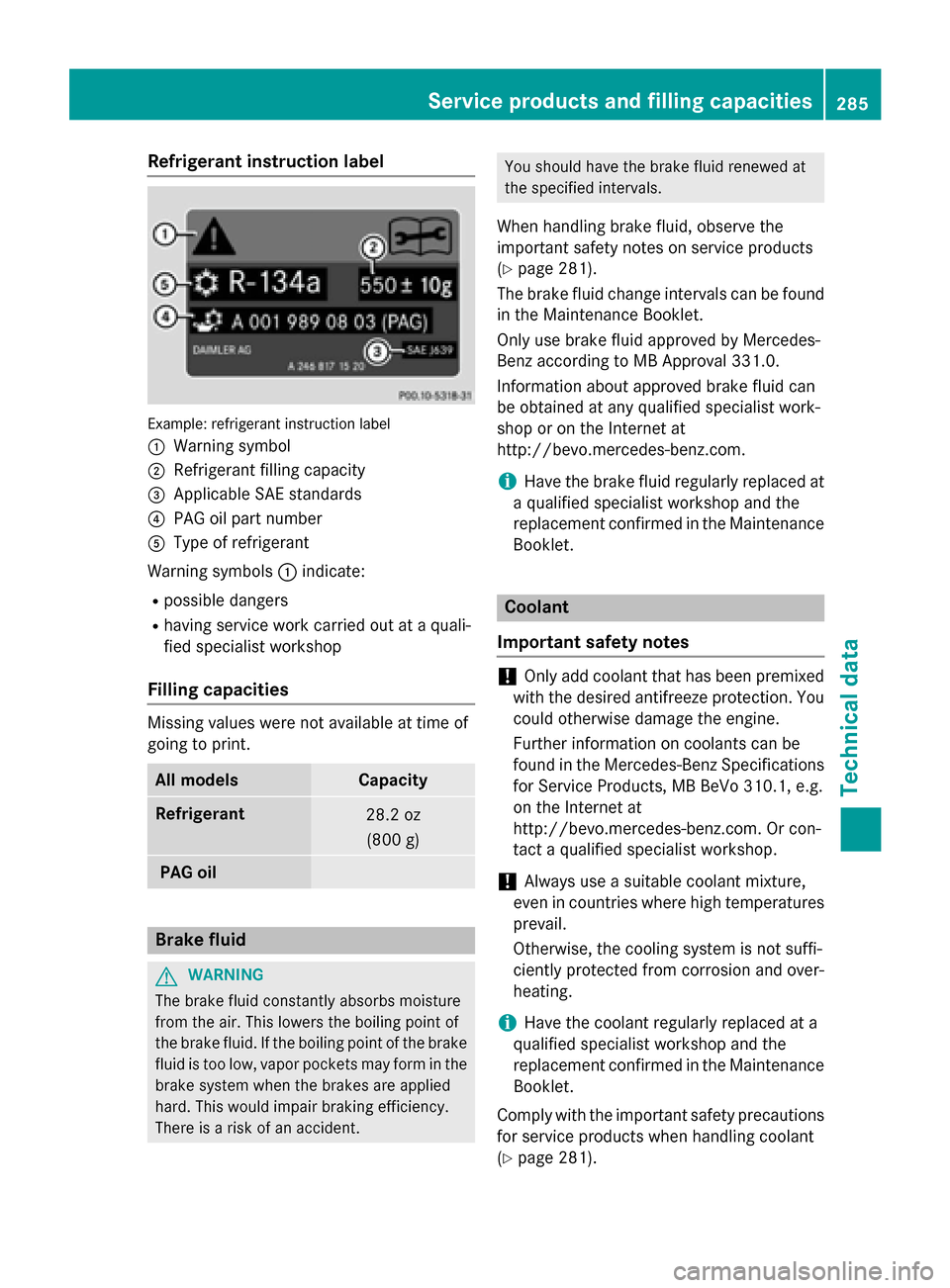
Refrigerant instructio
nlabel Example
:refrigerant instruction label
0043 Warning symbol
0044 Refrigerant filling capacity
0087 Applicabl eSAE standards
0085 PAG oi lpartn umber
0083 Type of refrigerant
Warning symbols 0043indicate:
R possible dangers
R having service work carrie doutataq uali-
fie ds pecialist workshop
Fillin gcapacities Missing value
sweren ot available at time of
going to print. Al
lm odels Capacity
Refrigerant
28.2 oz
(800 g) PA
Go il Brake fluid
G
WARNING
The brake fluidc onstantly absorbs moisture
from the air. This lowers the boiling point of
the brake fluid. If the boiling point of the brake fluidist oo low, vapor pockets may form in the
brake system when the brakes are applied
hard. This would impair braking efficiency.
There is arisk of an accident. You shoul
dhave the brake fluidr enewed at
the specified intervals.
When handling brake fluid, observe the
important safety notes on service products
(Y page 281).
The brake fluidc hange intervals can be found
in the Maintenance Booklet.
Only use brake fluida pproved by Mercedes-
Benz according to MB Approval 331.0.
Information abouta pproved brake fluidc an
be obtained at any qualified specialist work-
shop or on the Internet at
http://bevo.mercedes-benz.com.
i Have the brake fluidr
egularly replaced at
aq ualified specialist workshop and the
replacement confirmed in the Maintenance Booklet. Coolant
Important safety notes !
Only add coolant that has been premixed
with the desired antifreeze protection. You
could otherwise damage the engine.
Further information on coolants can be
found in the Mercedes-Benz Specifications for Service Products, MB BeVo 310.1, e.g.
on the Internet at
http://bevo.mercedes-benz.com .Orcon-
tact aqualified specialist workshop.
! Always use
asuitable coolant mixture,
even in countries where high temperatures
prevail.
Otherwise, the cooling system is not suffi-
ciently protected from corrosion and over-
heating.
i Have the coolant regularly replaced at a
qualified specialist workshop and the
replacement confirmed in the Maintenance Booklet.
Compl ywith the important safety precautions
for service products when handling coolant
(Y page 281). Servic
eproducts and filling capacities
285Technical data Z