Page 245 of 290

R
If the battery is fullyd ischarged, leave the battery that is being used to jump-start connected
for afew minutes before attempting to start. This charges the battery slightly.
R Make sure that the two vehicle sdonot touch.
Make sure that:
R the jumper cablesa re not damaged.
R when the jumper cablesa re connected to the battery, uninsulated sections of the terminal
clamp do not come into contact with other metal sections.
R the jumper cablesc annot come into contact with parts such as the V-belt pulley or the fan.
These parts move when the engine is started and whileitisr unning.
X Press the electric parking brake handle.
X Shift the transmission to Pwith the button in the center console.
X Remove the SmartKey from the ignition lock.
X Switch off all electrical consumers (e.g. radio, blower, etc.).
X Open the hood (Y page 218). Positio
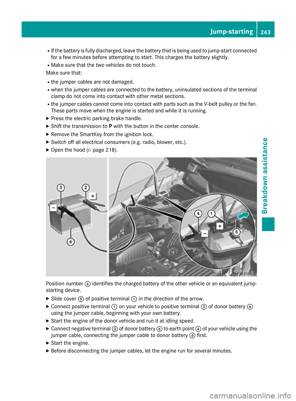
nnumber 0084identifie sthe charged battery of the other vehicle or an equivalent jump-
starting device.
X Slide cover 0083of positive terminal 0043in the direction of the arrow.
X Connect positive terminal 0043on yourv ehicle to positive terminal 0044of donor battery 0084
using the jumper cable,b eginning with yourown battery.
X Start the engine of the donor vehicle and run it at idling speed.
X Connect negative terminal 0087of donor battery 0084to earth point 0085of yourv ehicle using the
jumper cable,c onnecting the jumper cable to donor battery 0084first.
X Start the engine.
X Before disconnecting the jumper cables, let the engine run for several minutes. Jump-starting
243Breakdown assistance Z
Page 271 of 290

GVWR (Gross Vehicl
eWeight Rating)
The GVWR is the maximu mpermitted gross
weight of the fullyl oaded vehicle (weight of
the vehicle including all accessories, occu-
pants, fuel,l uggage and the drawbar nose-
weight if applicable).T he gross vehicle weight
rating is specified on the vehicle identification plate on the B-pilla ronthe driver's side.
Maximum loaded vehicle weight
The maximu mweight is the sum of the curb
weight of the vehicle ,the weight of the acces-
sories ,the total loadl imitand the weight of
the optional equipment installed at the fac-
tory.
Kilopascal (kPa)
Metric unit for tire pressure. 6.9 kPa is the
equivalent of 1psi.A nother unit for tire pres-
sure is bar. There are 100 kilopascals (kPa) to
1b ar.
Load index
In addition to the load-bearing index, the load index may alsobei mprinted on the sidewallof
the tire. This specifies the load-bearing capa-
city more precisely.
Curb weight
The weight of avehicle with standard equip-
ment including the maximu mcapacity of fuel,
oil and coolant. It alsoi ncludes the air-condi-
tioning system and optional equipment if
these are installed in the vehicle ,but does not
includ epassengers or luggage.
Maximum load rating
The maximu mloadr ating in kilograms or
pounds is the maximu mweight for which a
tire is approved.
Maximum permissible tire pressure
Maximu mpermissibl etire pressure for one
tire.
Maximum load on one tire
Maximu mloadono ne tire. This is calculated
by dividing the maximu maxle loadofo ne axle
by two. PSI (pounds per square inch)
As
tandard unit of measure for tire pressure.
Aspec tratio
Relationshi pbetwee ntire heigh tand tire
width in percent.
tire pressure
This is pressure inside the tire applying an
outward force to each square inch of the tire's surface. The tire pressure is specified in
pounds per square inch (psi), in kilopascal
(kPa) or in bar. The tire pressure shoul donly
be corrected when the tires are cold. For this,
the vehicle must have been stationary for at
least three hours or not have traveled more
than 1.6 km (1 mile)int his time.
Tire pressure of coldt ires
The tires are cold:
R if the vehicle has been parked without
direct sunlight on the tires for at least three
hours and
R if the vehicle has not been driven more than
1m ile (1.6 km)
Tread
The part of the tire that comes into contact
with the road.
Bead
The tire beade nsures that the tire sits
securel yonthe wheel. There are severa lsteel
wiresint he beadtop revent the tire from
coming loose from the wheelr im.
Sidewall
The part of the tire betwee nthe tread and the
bead.
Weight of optional extras
The combined weight of those optional extras
that weigh more than the replaced standard
part and more than 2.3 kilograms (5 lbs).
These optional extras, such as high-perform-
ance brakes, level control, aroof rack or a
high-performance battery, are not included in Alla
bout wheels and tires
269Wheelsand tires Z
Page 274 of 290

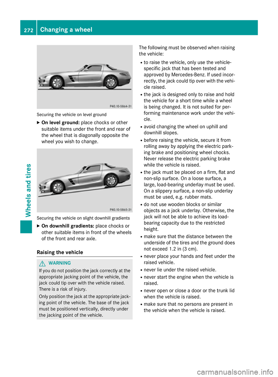
Securing the vehicle on level ground
X On level ground: place chocks or other
suitabl eitem sunder the front and rea rof
the wheel that is diagonall yopposite the
wheel yo uwishtoc hange. Securing the vehicle on slight downhil
lgradients
X On downhill gradients: place chocks or
othe rsuitabl eitem sinf ront of the wheels
of the front and rea raxle.
Raisin gthe vehicle G
WARNING
If yo udon ot position the jack correctly at the
appropriate jacking point of the vehicle ,the
jack could tip ove rwitht he vehicle raised.
There is ariskofi njury.
Only position the jack at the appropriate jack-
ing point of the vehicle .The base of the jack
mus tbep ositioned vertically ,directl yunder
the jacking point of the vehicle. The following mus
tbeo bserve dwhenr aising
the vehicle:
R to raise the vehicle ,only us ethe vehicle-
specifi cjack that ha sbeent ested and
approved by Mercedes-Benz. If used incor-
rectly, the jack could tip ove rwitht he vehi-
cle raised.
R the jack is designe donly to raise and hold
the vehicle for ashort time whil eawheel
is being changed .Itisnot suited for per-
forming maintenance work under the vehi-
cle.
R avoid changing the wheel on uphil land
downhil lslopes.
R before raising the vehicle ,secure it from
rolling away by applying the electri cpark-
ing brake and positioning wheel chocks.
Neve rrelease the electri cparking brake
whil ethe vehicle is raised.
R the jack mus tbep lace donaf irm,flata nd
non-slip surface. On aloose surface, a
large ,load-bearing underlay mus tbeu sed.
On aslippery surface, anon-slip underlay
mus tbeu sed, e.g. rubber mats.
R do not us ewoodenb locks or similar
objects as ajack underlay .Otherwise, the
jack will not be able to achieve its load-
bearing capacity du etothe restricted
height.
R make sure that the distance between the
underside of the tire sand the ground does
not excee d1.2 in (3 cm).
R never place your hands and fee tunder the
raised vehicle.
R never li eunder the raised vehicle.
R never star tthe engine when the vehicle is
raised.
R never ope norclosead oorort he trunk lid
when the vehicle is raised.
R make sure that no persons are present in
the vehicle when the vehicle is raised. 272
Changing
awheelWheels and tires