2015 MERCEDES-BENZ SLK-CLASS ROADSTER tow
[x] Cancel search: towPage 309 of 358
XSwitch on the hazard warning lamps (Y page 111).
iWhen towing with the hazard warning
lamps switched on, use the combination
switch as usual to signal a change of direc- tion. In this case, only the indicator lamps
for the direction of travel flash. When you
reset the combination switch, the hazard
warning flashers start flashing again.
X Turn the SmartKey to position 2in the igni-
tion lock.
X When the vehicle is stationary, depress the
brake pedal and keep it depressed.
X Vehicles with manual transmission:
depress the clutch pedal fully and shift to
neutral.
or
X Vehicles with automatic transmission:
shift the automatic transmission to posi- tion N.
X Release the brake pedal.
X Release the electric parking brake.
It is important that you observe the safety
instructions when towing away your vehicle( Y page 305).
Towing the vehicle with the rear axle
raised
!
The ignition must be switched off if you
are towing the vehicle with the rear axle
raised. Intervention by ESP ®
could other-
wise damage the brake system.
X Switch on the hazard warning lamps (Y page 111).
X Bring the front wheels into the straight-
ahead position.
X Turn the SmartKey to position 0in the igni-
tion lock and remove the SmartKey from
the ignition lock.
X When leaving the vehicle, take the Smart-
Key or the KEYLESS-GO key with you. When towing your vehicle with the rear axle
raised, it is important that you observe the
safety instructions (
Ypage 305).
Transporting the vehicle
!
You may only secure the vehicle by the
wheels, not by parts of the vehicle such as
axle or steering components. Otherwise,
the vehicle could be damaged.
The towing eye can be used to pull the vehicle
onto a trailer or transporter for transporting
purposes. X Vehicles with manual transmission:
depress the clutch pedal fully and shift to
neutral.
X Vehicles with automatic transmission:
turn the SmartKey to position 2in the igni-
tion lock.
X Move the selector lever to N.
As soon as the vehicle has been loaded: X Prevent the vehicle from rolling away by
applying the electric parking brake.
X Vehicles with manual transmission:
fully depress the clutch pedal and engage
first or reverse gear.
X Vehicles with automatic transmission:
move the selector lever to P.
X Turn the SmartKey to position 0in the igni-
tion lock and remove the SmartKey from
the ignition lock.
X Secure the vehicle.
Tow-starting (emergency engine
starting)
!
Vehicles with automatic transmission
must not be tow-started. You could other-
wise damage the automatic transmission.
iYou can find information on "Jump-start-
ing" under ( Ypage 303).
Towing and tow-starting307
Roadside Assistance
Z
Page 310 of 358
Before tow-starting:R the battery must be connected
R the engine must be cold
R the exhaust system must have cooled down
When tow-starting, it is important that you
observe the safety instructions ( Ypage 305).
X Switch on the hazard warning lamps(Y page 111).
X Install the towing eye ( Ypage 306).
X Secure the rigid towing bar or the towing
rope.
X Depress and hold the brake pedal.
X Turn the SmartKey to position 2in the igni-
tion lock.
X Depress the clutch pedal fully, engage sec-
ond gear and keep the clutch pedal
depressed.
X Release the brake pedal.
X Tow-start the vehicle.
X Release the clutch pedal slowly; do not
depress the accelerator pedal while doingso.
X As soon as the engine starts, depress the
clutch pedal immediately and shift to neu-
tral.
X Stop at a suitable place, in accordance with
the traffic conditions.
X Depress the parking brake.
X Remove the rigid towing bar or towing rope.
X Remove the towing eye ( Ypage 306).
X Switch off the hazard warning lamps.
Fuses
Important safety notes
GWARNING
If you manipulate or bridge a faulty fuse or if
you replace it with a fuse with a higher amper-
age, the electric cables could be overloaded.
This could result in a fire. There is a risk of an
accident and injury.
Always replace faulty fuses with the specified new fuses having the correct amperage.
!Only use fuses that have been approved
for Mercedes-Benz vehicles and which
have the correct fuse rating for the system
concerned. Otherwise, components or sys-
tems could be damaged.
The fuses in your vehicle serve to close down faulty circuits. If a fuse blows, all the compo- nents on the circuit and their functions stop
operating.
Blown fuses must be replaced with fuses of
the same rating, which you can recognize by
the color and value. The fuse ratings are listed
in the fuse allocation chart.
If a newly inserted fuse also blows, have the
cause traced and rectified at a qualified spe-
cialist workshop, e.g. an authorized
Mercedes-Benz Center.
Before changing a fuse
X Secure the vehicle against rolling away (Y page 161).
X Switch off all electrical consumers.
X Turn the SmartKey to position 0in the igni-
tion lock and remove it ( Ypage 139).
or
X On vehicles with KEYLESS-GO, make sure
the ignition is switched off ( Ypage 140).
All indicator lamps in the instrument cluster
must be off.
The fuses are located in various fuse boxes:
R Fuse box in the engine compartment on the
left-hand side of the vehicle, when viewed
in the direction of travel
R Fuse box in the trunk
The fuse allocation chart is located in the
vehicle tool kit in the stowage compartment
under the trunk floor ( Ypage 294).
308Fuses
Roadside Assistance
Page 340 of 358
Mounting a new wheel
GWARNING
Oiled or greased wheel bolts or damaged
wheel bolts/hub threads can cause the wheelbolts to come loose. As a result, you could
lose a wheel while driving. There is a risk of
accident.
Never oil or grease wheel bolts. In the event ofdamage to the threads, contact a qualified
specialist workshop immediately. Have the
damaged wheel bolts or hub threads
replaced/renewed. Do not continue driving.
GWARNING
If you tighten the wheel bolts or wheel nuts
when the vehicle is raised, the jack could tip
over. There is a risk of injury.
Only tighten the wheel bolts or wheel nuts
when the vehicle is on the ground.
Always pay attention to the instructions and
safety notes in the "Changing a wheel" sec-
tion ( Ypage 334).
Only use wheel bolts that have been designed for the wheel and the vehicle. For safety rea-
sons, Mercedes-Benz recommends that you
only use wheel bolts which have been
approved for Mercedes-Benz vehicles and the
respective wheel.
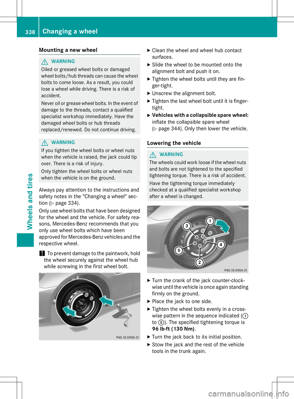
!To prevent damage to the paintwork, hold
the wheel securely against the wheel hub
while screwing in the first wheel bolt.
X Clean the wheel and wheel hub contact
surfaces.
X Slide the wheel to be mounted onto the
alignment bolt and push it on.
X Tighten the wheel bolts until they are fin-ger-tight.
X Unscrew the alignment bolt.
X Tighten the last wheel bolt until it is finger-
tight.
X Vehicles with a collapsible spare wheel:
inflate the collapsible spare wheel( Y page 344). Only then lower the vehicle.
Lowering the vehicle
GWARNING
The wheels could work loose if the wheel nuts
and bolts are not tightened to the specified
tightening torque. There is a risk of accident.
Have the tightening torque immediately
checked at a qualified specialist workshop
after a wheel is changed.
X Turn the crank of the jack counter-clock-
wise until the vehicle is once again standing
firmly on the ground.
X Place the jack to one side.
X Tighten the wheel bolts evenly in a cross-
wise pattern in the sequence indicated ( :
to A ). The specified tightening torque is
96 lb-ft (130 Nm) .
X Turn the jack back to its initial position.
X Stow the jack and the rest of the vehicle
tools in the trunk again.
338Changing a wheel
Wheels and tires
Page 346 of 358
found on the wheel or under "Technical data"( Y page 346).
An emergency spare wheel may also be
mounted against the direction of rotation.
Observe the time restriction on use as well as
the speed limitation specified on the emer-
gency spare wheel.
Replace the tires after six years at the latest,
regardless of wear. This also applies to the
emergency spare wheel.
iWhen you are driving with the collapsible
spare wheel mounted, the tire pressure
loss warning system or the tire pressure
monitor cannot function reliably. Only
restart the tire pressure loss warning sys-
tem/the tire pressure monitor when the
damaged wheel has been replaced with a
new wheel.
Vehicles with tire pressure monitor:
after mounting an emergency spare wheel,
the system may still display the tire pres-
sure of the removed wheel for a few
minutes. The value displayed for the moun- ted emergency spare wheel is not the sameas the current tire pressure of the emer-
gency spare wheel.
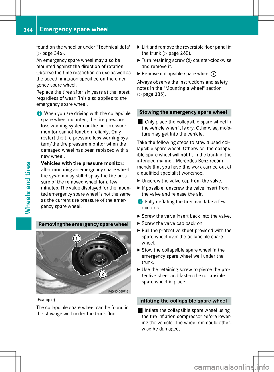
Removing the emergency spare wheel
(Example)
The collapsible spare wheel can be found in
the stowage well under the trunk floor. X
Lift and remove the reversible floor panel in
the trunk ( Ypage 260).
X Turn retaining screw ;counter-clockwise
and remove it.
X Remove collapsible spare wheel :.
Always observe the instructions and safety
notes in the "Mounting a wheel" section( Y page 335).
Stowing the emergency spare wheel
!
Only place the collapsible spare wheel in
the vehicle when it is dry. Otherwise, mois-
ture may get into the vehicle.
Take the following steps to stow a used col-
lapsible spare wheel. Otherwise, the collaps-
ible spare wheel will not fit in the trunk in the
intended manner. Mercedes-Benz recom-
mends that you have this work carried out at
a qualified specialist workshop.
X Unscrew the valve cap from the valve.
X If possible, unscrew the valve insert from
the valve and release the air.
iFully deflating the tires can take a few
minutes.
X Screw the valve insert back into the valve.
X Screw the valve cap back on.
X Pull the protective sheet provided with the
spare wheel over the collapsible spare
wheel.
X Stow the collapsible spare wheel in the
emergency spare wheel well under thetrunk.
X Use the retaining screw to pierce the pro-
tective sheet and fasten the collapsible
spare wheel in place.
Inflating the collapsible spare wheel
!
Inflate the collapsible spare wheel using
the tire inflation compressor before lower-
ing the vehicle. The wheel rim could other-
wise be damaged.
344Emergency spare wheel
Wheels and tires
Page 347 of 358
!Do not operate the tire inflation compres-
sor for longer than ten minutes at a time
without a break. It may otherwise overheat.
The tire inflation compressor can be oper-
ated again once it has cooled down.
X Mount the collapsible spare wheel as
described ( Ypage 335).
The collapsible spare wheel must be moun-
ted before it is inflated.
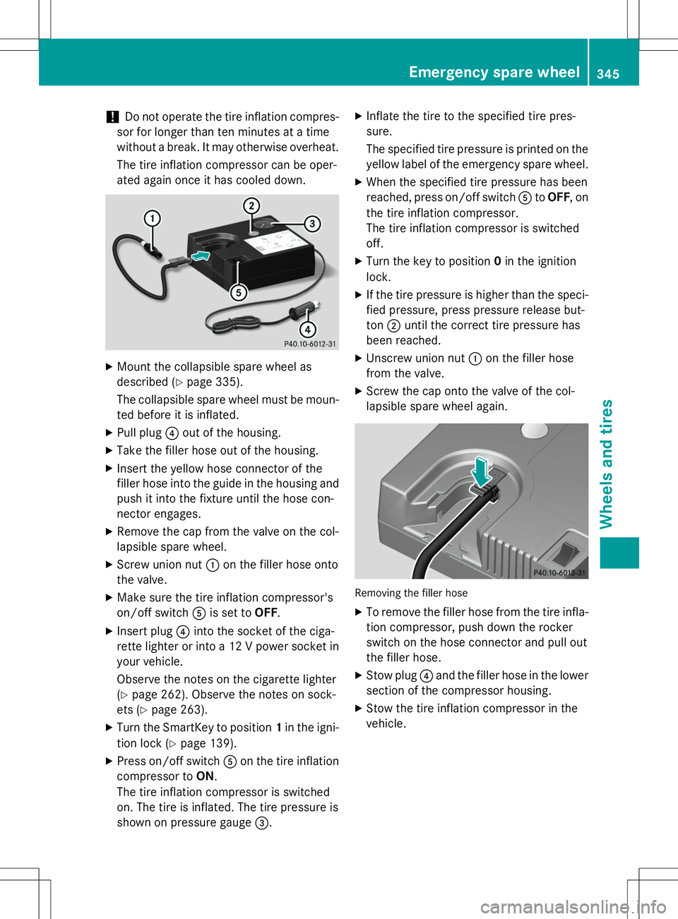
X Pull plug ?out of the housing.
X Take the filler hose out of the housing.
X Insert the yellow hose connector of the
filler hose into the guide in the housing and
push it into the fixture until the hose con-
nector engages.
X Remove the cap from the valve on the col-
lapsible spare wheel.
X Screw union nut :on the filler hose onto
the valve.
X Make sure the tire inflation compressor's
on/off switch Ais set to OFF.
X Insert plug ?into the socket of the ciga-
rette lighter or into a 12 V power socket in
your vehicle.
Observe the notes on the cigarette lighter ( Y page 262). Observe the notes on sock-
ets ( Ypage 263).
X Turn the SmartKey to position 1in the igni-
tion lock ( Ypage 139).
X Press on/off switch Aon the tire inflation
compressor to ON.
The tire inflation compressor is switched
on. The tire is inflated. The tire pressure is
shown on pressure gauge =. X
Inflate the tire to the specified tire pres-sure.
The specified tire pressure is printed on the
yellow label of the emergency spare wheel.
X When the specified tire pressure has been
reached, press on/off switch AtoOFF , on
the tire inflation compressor.
The tire inflation compressor is switchedoff.
X Turn the key to position 0in the ignition
lock.
X If the tire pressure is higher than the speci-
fied pressure, press pressure release but-ton ;until the correct tire pressure has
been reached.
X Unscrew union nut :on the filler hose
from the valve.
X Screw the cap onto the valve of the col-
lapsible spare wheel again.
Removing the filler hose
XTo remove the filler hose from the tire infla-
tion compressor, push down the rocker
switch on the hose connector and pull out
the filler hose.
X Stow plug ?and the filler hose in the lower
section of the compressor housing.
X Stow the tire inflation compressor in thevehicle.
Emergency spare wheel345
Wheels and tires
Z