2015 MERCEDES-BENZ SLK-Class ground
[x] Cancel search: groundPage 20 of 358

Increased vehicle weight due to
optional equipment (definition) ...... 330
Kilopascal (kPa) (definition) ........... 330
Labeling (overview) ........................ 326
Load bearing index (definition) ...... 331
Load index .....................................3 28
Load index (definition) ................... 331
M+S tires ....................................... 312
Maximum loaded vehicle weight
(definition) ..................................... 330
Maximum load on a tire (defini-
tion) ............................................... 331
Maximum permissible tire pres-
sure (definition) ............................ .331
Maximum tire load ......................... 328
Maximum tire load (definition) ....... 331
MOExtended tires .......................... 312
Optional equipment weight (defi-
nition) ............................................ 331
Overview ........................................ 310
PSI (pounds per square inch) (def-
inition) .......................................... .331
Replacing ....................................... 332
Service life ..................................... 312
Sidewall (definition) ....................... 331
Speed rating (definition) ................ 330
Storing .......................................... .332
Structure and characteristics
(definition) ..................................... 329
Summer tires ................................. 312
Temperature .................................. 325
TIN (Tire Identification Number)
(definition) ..................................... 331
Tire bead (definition) ..................... .331
Tire pressure (definition) ................ 331
Tire pressures (recommended) ...... 330
Tire size (data) ............................... 337
Tire size designation, load-bearing capacity, speed rating .................... 326
Tire tread ....................................... 311
Tire tread (definition) ..................... 331
Total load limit (definition) ............. 332
Traction ......................................... 325
Traction (definition) ....................... 332
Tread wea r..................................... 325
Uniform Tire Quality Grading
Standards ...................................... 324 Uniform Tire Quality Grading
Standards (definition) .................... 330
Wear indicator (definition) ............. 332
Wheel and tire combination ........... 339
Wheel rim (definition) .................... 330
see Flat tire
Towing
Important safety guidelines ........... 303
Installing the towing eye ................ 304
Removing the towing eye ............... 304
With the rear axle raised ................ 305
Towing away
With both axles on the ground ....... 305
Tow-starting
Emergency engine starting ............ 306
Important safety notes .................. 303
Installing the towing eye ................ 304
Removing the towing eye ............... 304
Transmission
Selector lever ................................ 151
see Automatic transmission
see Manual transmission
Transporting the vehicle .................. 305
Trim pieces (cleaning instruc-
tions) .................................................. 288
Trip computer (on-board com-
puter) .................................................. 197
Trip odometer Calling up ....................................... 197
Resetting (on-board computer) ...... 198
Trunk
Emergency release .......................... 82
Important safety notes .................... 80
Locking separately ........................... 82
Opening/closing (manually from
outside) ............................................ 81
Opening (automatically from out-
side) ................................................. 82
Overview .......................................... 80
Trunk lid
Display message ............................ 240
Opening/closing .............................. 80
Opening dimensions ...................... 353
Trunk load (maximum) ...................... 35318
Index
Page 165 of 358

The function of the electric parking brake is
dependent on the on-board voltage. If the on-
board voltage is low or there is a malfunction in the system, it may not be possible to apply
the released parking brake.
X If this is the case, only park the vehicle on
level ground and secure it to prevent it roll-
ing away.
X Vehicles with automatic transmission:
shift the automatic transmission to posi-
tion P.
X Vehicles with manual transmission:
engage first gear.
It may not be possible to release an applied
parking brake if the on-board voltage is low or
there is a malfunction in the system. Contact a qualified specialist workshop.
i The electric parking brake performs a
function test at regular intervals while the
engine is switched off. The sounds that can
be heard while this is occurring are normal.
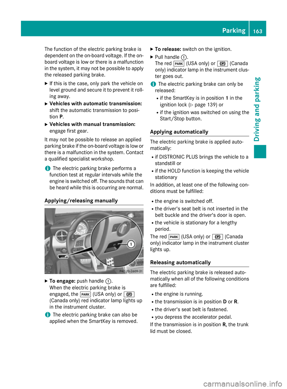
Applying/releasing manually X
To engage: push handle 0043.
When the electric parking brake is
engaged, the 0049(USA only) or 0024
(Canada only) red indicator lamp lights up
in the instrument cluster.
i The electric parking brake can also be
applied when the SmartKey is removed. X
To release: switch on the ignition.
X Pull handle 0043.
The red 0049(USA only) or 0024(Canada
only) indicator lamp in the instrument clus-
ter goes out.
i The electric parking brake can only be
released:
R if the SmartKey is in position 1in the
ignition lock (Y page 139) or
R if the ignition was switched on using the
Start/Stop button.
Applying automatically The electric parking brake is applied auto-
matically:
R if DISTRONIC PLUS brings the vehicle to a
standstill or
R if the HOLD function is keeping the vehicle
stationary
In addition, at least one of the following con-
ditions must be fulfilled:
R the engine is switched off.
R the driver's seat belt is not inserted in the
belt buckle and the driver's door is open.
R the vehicle is stationary for a lengthy
period.
The red 0049(USA only) or 0024(Canada
only) indicator lamp in the instrument cluster
lights up.
Releasing automatically The electric parking brake is released auto-
matically when all of the following conditions
are fulfilled:
R the engine is running.
R the transmission is in position Dor R.
R the driver's seat belt is fastened.
R you depress the accelerator pedal.
If the transmission is in position R, the trunk
lid must be closed. Parking
163Driving and parking Z
Page 294 of 358

Useful information
i This Operator's manual describes all
models and all standard and optional equip- ment of your vehicle available at the time of
publication of the Operator's manual.
Country-specific differences are possible.
Please note that your vehicle may not be
equipped with all features described. This
also applies to safety-related systems and
functions.
i Read the information on qualified special-
ist workshops (Y page 26). Where will I find...?
Vehicle tool kit
General notes The vehicle tool kit can be found in the stow-
age well under the trunk floor.
i Apart from certain country-specific varia-
tions, the vehicles are not equipped with a
tire-change tool kit. Some tools for chang-
ing a wheel are specific to the vehicle. For
more information on which tools are
required to perform a wheel change on your
vehicle, consult a qualified specialist work-
shop.
Tools required for changing a wheel may
include, for example:
R Jack
R Wheel chock
R Lug wrench
R Ratchet wrench
R Alignment bolt Vehicles with a collapsible spare wheel 0043
Folding wheel chock
0044 Fuse allocation chart
0087 Jack
0085 Sheet for faulty wheel
0083 Alignment bolt
0084 Lug wrench
006B Towing eye
006C Valve extractor
006D Tire inflation compressor
X Lift the trunk floor up.
X Remove collapsible spare wheel
(Y page 341). Flat tire
Preparing the vehicle
Your vehicle may be equipped with: R MOExtended tires (tires with run-flat prop-
erties) (Y page 293)
Vehicle preparation is not necessary on
vehicles with MOExtended tires
R an emergency spare wheel (Y page 341)
Information on changing/mounting a wheel
(Y page 332).
X Stop the vehicle on solid, non-slippery and
level ground, as far away as possible from
traffic.
X Switch on the hazard warning lamps.
X Secure the vehicle against rolling away
(Y page 161). 292
Flat tireBreakdown assistance
Page 302 of 358

The jump-starting connection point is in the
engine compartment.
If, at low temperatures, the indicator lamps/
warning lamps in the instrument cluster do
not light up, it is highly likely that the dis-
charged battery has frozen. In this case, you
may neither charge the battery nor jump-start
the vehicle. The service life of a thawed-out
battery may be shorter. The starting charac-
teristics can be impaired, particularly at low
temperatures. Have the thawed-out battery
checked at a qualified specialist workshop.
Read the battery charger's operating instruc- tions before charging the battery.
X Open the hood.
X Connect the battery charger to the positive
terminal and ground point in the same
order as when connecting the donor bat-
tery in the jump-starting procedure
(Y page 301). 300
Battery (vehicle)Breakdown assistance
Page 303 of 358

Jump-starting
For the jump-starting procedure, use only the jump-starting connection point, consisting of a positive terminal and a ground point, in the engine compartment. G
WARNING
Battery acid is caustic. There is a risk of injury.
Avoid contact with the skin, eyes or clothing. Do not inhale any battery gases. Do not lean over the battery. Keep children away from batteries. Wash battery acid immediately with water and seek
medical attention. G
WARNING
During charging and jump-starting, explosive gases can escape from the battery. There is a risk of an explosion.
Particularly avoid fire, open flames, creating sparks and smoking. Ensure there is sufficient ven-
tilation while charging and jump-starting. Do not lean over a battery. G
WARNING
During the charging process, a battery produces hydrogen gas. If a short circuit occurs or sparks
are created, the hydrogen gas can ignite. There is a risk of an explosion.
R Make sure that the positive terminal of a connected battery does not come into contact with
vehicle parts.
R Never place metal objects or tools on a battery.
R It is important that you observe the described order of the battery terminals when connecting
and disconnecting a battery.
R When jump-starting, make sure that the battery poles with identical polarity are connected.
R It is particularly important to observe the described order when connecting and disconnecting
the jumper cables.
R Never connect or disconnect the battery terminals while the engine is running. G
WARNING
A discharged battery can freeze at temperatures below freezing point. When jump-starting the
vehicle or charging the battery, gases can escape from the battery. There is a risk of an explosion.
Allow the frozen battery to thaw out before charging it or jump-starting.
! Avoid repeated and lengthy starting attempts. Otherwise, the catalytic converter could be
damaged by the non-combusted fuel.
If, at low temperatures, the indicator lamps/warning lamps in the instrument cluster do not
light up, it is highly likely that the discharged battery has frozen. In this case, you may neither
charge the battery nor jump-start the vehicle. The service life of a thawed-out battery may be
shorter. The starting characteristics can be impaired, particularly at low temperatures. Have
the thawed-out battery checked at a qualified specialist workshop. Jump-starting
301Breakdown assistance Z
Page 305 of 358

Position number
0084identifies the charged battery of the other vehicle or an equivalent jump-
starting device.
X Slide cover 0043of positive terminal 0044in the direction of the arrow.
X Connect positive terminal 0044on your vehicle to positive terminal 0087of donor battery 0084
using the jumper cable, always begin with positive terminal 0044on your own vehicle first.
X Start the engine of the donor vehicle and run it at idling speed.
X Connect negative terminal 0085of donor battery 0084to ground point 0083of your vehicle using
the jumper cable, connecting the jumper cable to battery of other vehicle 0084first.
X Start the engine.
X Before disconnecting the jumper cables, let the engine run for several minutes.
X First, remove the jumper cables from ground point 0083and negative terminal 0085, then from
positive clamp 0044and positive terminal 0087. Begin each time at the contacts on your own
vehicle first.
X Close cover 0043of positive terminal 0044after removing the jumper cables.
X Have the battery checked at a qualified specialist workshop.
i Jump-starting is not considered to be a normal operating condition.
i Jumper cables and further information regarding jump-starting can be obtained at any
qualified specialist workshop. Towing and tow-starting
Important safety notes
! Vehicles with automatic transmission
must not be tow-started. You could other-
wise damage the automatic transmission. G
WARNING
If the weight of the vehicle to be towed or tow- started is greater than the permissible gross
weight of your vehicle:
R the towing eye could detach itself
R the vehicle/trailer combination could roll-
over.
There is a risk of an accident.
When towing or tow-starting another vehicle,
its weight should not be greater than the per-
missible gross weight of your vehicle. !
If DISTRONIC PLUS or the HOLD function
is activated, the vehicle brakes automati-
cally in certain situations. To prevent dam-
age to the vehicle, deactivate DISTRONIC
PLUS and the HOLD function in the follow- ing or other similar situations:
R when towing the vehicle
R in the car wash
! Only secure the tow rope or tow bar at the
towing eyes. Otherwise, the vehicle could
be damaged.
! Do not use the towing eye for recovery,
this could damage the vehicle. If in doubt,
recover the vehicle with a crane.
! Drive slowly and smoothly when towing.
Excessive tractive power could otherwise
damage the vehicles.
! Do not tow with sling-type equipment.
This could damage the vehicle.
! On vehicles with KEYLESS-GO, use the
SmartKey instead of the Start/Stop but-
ton. Turn the SmartKey to position 2in the Towing and tow-starting
303Breakdown assistance Z
Page 307 of 358

Towing the vehicle with the rear axle
raised
! The ignition must be switched off if you
are towing the vehicle with the rear axle
raised. Intervention by ESP ®
could other-
wise damage the brake system.
X Switch on the hazard warning lamps
(Y page 111).
X Bring the front wheels into the straight-
ahead position.
X Turn the SmartKey to position 0in the igni-
tion lock and remove the SmartKey from
the ignition lock.
X When leaving the vehicle, take the Smart-
Key or the KEYLESS-GO key with you.
When towing your vehicle with the rear axle
raised, it is important that you observe the
safety instructions (Y page 303).Towing a vehicle with both axles on
the ground G
WARNING
You can no longer steer the vehicle if the
steering wheel lock has been engaged. There is a risk of an accident.
Always switch off the ignition when towing the
vehicle with a tow cable or a tow bar.
X Switch on the hazard warning lamps
(Y page 111).
i When towing with the hazard warning
lamps switched on, use the combination
switch as usual to signal a change of direc- tion. In this case, only the indicator lamps
for the direction of travel flash. When you
reset the combination switch, the hazard
warning flashers start flashing again.
X Turn the SmartKey to position 2in the igni-
tion lock.
X When the vehicle is stationary, depress the
brake pedal and keep it depressed. X
Vehicles with manual transmission:
depress the clutch pedal fully and shift to
neutral.
or
X Vehicles with automatic transmission:
shift the automatic transmission to posi-
tion N.
X Release the brake pedal.
X Release the electric parking brake.
It is important that you observe the safety
instructions when towing away your vehicle
(Y page 303). Transporting the vehicle
! You may only secure the vehicle by the
wheels, not by parts of the vehicle such as axle or steering components. Otherwise,
the vehicle could be damaged.
The towing eye can be used to pull the vehicle
onto a trailer or transporter for transporting
purposes.
X Vehicles with manual transmission:
depress the clutch pedal fully and shift to
neutral.
X Vehicles with automatic transmission:
turn the SmartKey to position 2in the igni-
tion lock.
X Move the selector lever to N.
As soon as the vehicle has been loaded:
X Prevent the vehicle from rolling away by
applying the electric parking brake.
X Vehicles with manual transmission:
fully depress the clutch pedal and engage
first or reverse gear.
X Vehicles with automatic transmission:
move the selector lever to P.
X Turn the SmartKey to position 0in the igni-
tion lock and remove the SmartKey from
the ignition lock.
X Secure the vehicle. Towing and tow-starting
305Breakdown assistance Z
Page 335 of 358

Cleaning the wheels
G
WARNING
The water jet from a circular jet nozzle (dirt
blasters) can cause invisible exterior damage to the tires or chassis components. Compo-
nents damaged in this way may fail unexpect-edly. There is a risk of an accident.
Do not use power washers with circular jet
nozzles to clean the vehicle. Have damaged
tires or chassis components replaced imme-
diately. Mounting a wheel
Preparing the vehicle X
Stop the vehicle on solid, non-slippery and
level ground.
X Apply the electric parking brake manually.
X Bring the front wheels into the straight-
ahead position.
X Vehicles with manual transmission:
fully depress the clutch pedal and engage
first or reverse gear.
X Vehicles with automatic transmission:
move the selector lever to P.
X Switch off the engine.
X Vehicles without KEYLESS-GO: remove
the SmartKey from the ignition lock.
X Vehicles with KEYLESS-GO: open the
driver's door.
The on-board electronics now have status
0. This is the same as the SmartKey having
been removed.
X Vehicles with KEYLESS-GO: remove the
Start/Stop button from the ignition lock
(Y page 140).
X If included in the vehicle equipment,
remove the tire-change tool kit from the
vehicle.
X Secure the vehicle to prevent it from rolling
away. i
Due to differences in vehicle equipment,
not all vehicles are equipped with a tire-
change tool kit. For information on which
tools are required to perform a wheel
change on your vehicle, consult an author- ized Mercedes-Benz Center.
Necessary wheel-changing tools can
include, for example:
R Jack
R Wheel chock
R Lug wrench
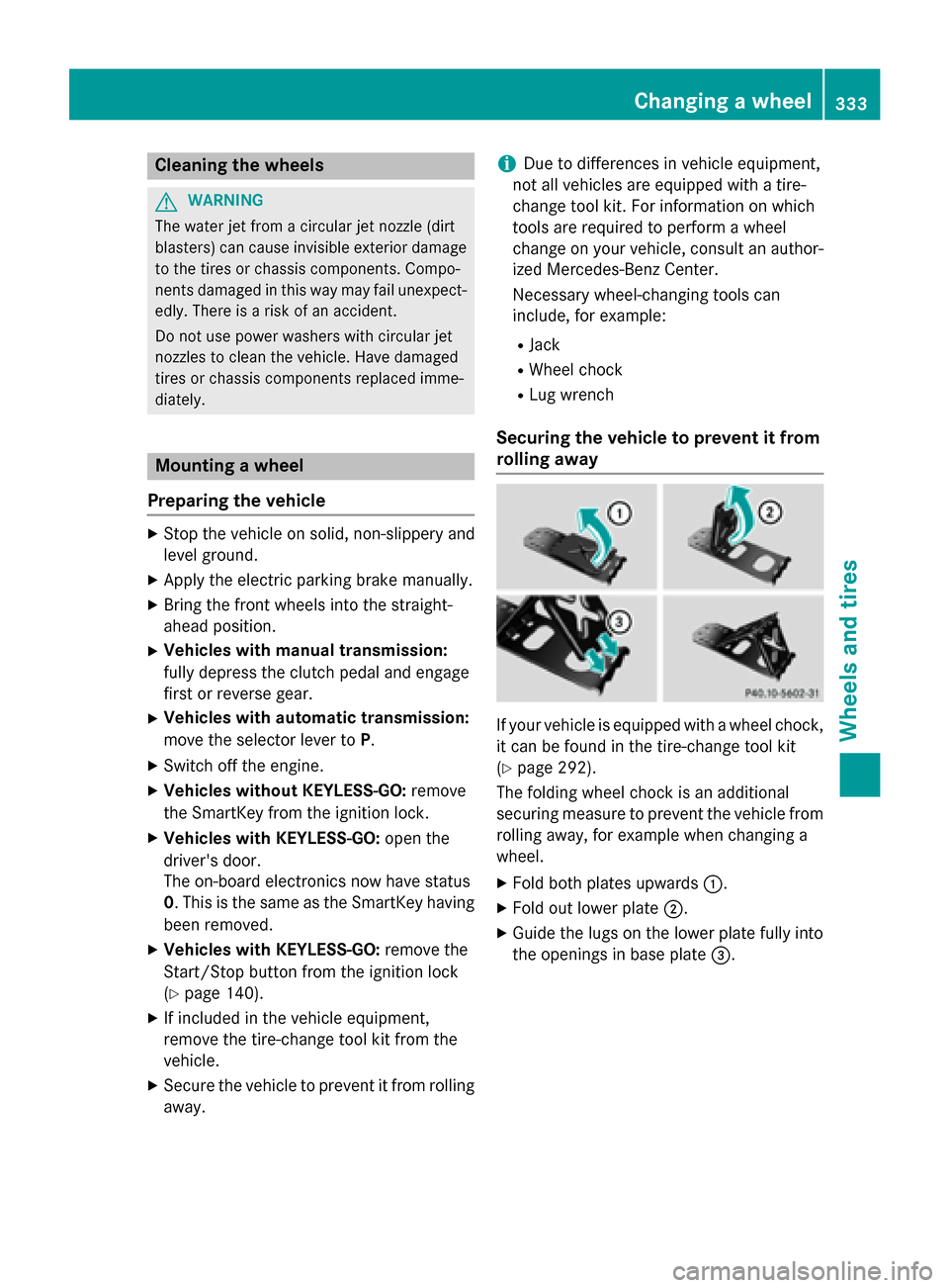
Securing the vehicle to prevent it from
rolling away If your vehicle is equipped with a wheel chock,
it can be found in the tire-change tool kit
(Y page 292).
The folding wheel chock is an additional
securing measure to prevent the vehicle from
rolling away, for example when changing a
wheel.
X Fold both plates upwards 0043.
X Fold out lower plate 0044.
X Guide the lugs on the lower plate fully into
the openings in base plate 0087. Changing a wheel
333Wheels and tires Z