2015 MERCEDES-BENZ SLK-Class change time
[x] Cancel search: change timePage 294 of 358

Useful information
i This Operator's manual describes all
models and all standard and optional equip- ment of your vehicle available at the time of
publication of the Operator's manual.
Country-specific differences are possible.
Please note that your vehicle may not be
equipped with all features described. This
also applies to safety-related systems and
functions.
i Read the information on qualified special-
ist workshops (Y page 26). Where will I find...?
Vehicle tool kit
General notes The vehicle tool kit can be found in the stow-
age well under the trunk floor.
i Apart from certain country-specific varia-
tions, the vehicles are not equipped with a
tire-change tool kit. Some tools for chang-
ing a wheel are specific to the vehicle. For
more information on which tools are
required to perform a wheel change on your
vehicle, consult a qualified specialist work-
shop.
Tools required for changing a wheel may
include, for example:
R Jack
R Wheel chock
R Lug wrench
R Ratchet wrench
R Alignment bolt Vehicles with a collapsible spare wheel 0043
Folding wheel chock
0044 Fuse allocation chart
0087 Jack
0085 Sheet for faulty wheel
0083 Alignment bolt
0084 Lug wrench
006B Towing eye
006C Valve extractor
006D Tire inflation compressor
X Lift the trunk floor up.
X Remove collapsible spare wheel
(Y page 341). Flat tire
Preparing the vehicle
Your vehicle may be equipped with: R MOExtended tires (tires with run-flat prop-
erties) (Y page 293)
Vehicle preparation is not necessary on
vehicles with MOExtended tires
R an emergency spare wheel (Y page 341)
Information on changing/mounting a wheel
(Y page 332).
X Stop the vehicle on solid, non-slippery and
level ground, as far away as possible from
traffic.
X Switch on the hazard warning lamps.
X Secure the vehicle against rolling away
(Y page 161). 292
Flat tireBreakdown assistance
Page 296 of 358
Important safety notes
G
WARNING
When driving in emergency mode, the driving characteristics deteriorate, e.g. when corner-
ing, accelerating quickly and when braking.
There is a risk of an accident.
Do not exceed the stated maximum speed.
Avoid abrupt steering and driving maneuvers,
and driving over obstacles (curbs, potholes,
off-road). This applies in particular to a laden
vehicle.
Stop driving in emergency mode if:
R you hear banging noises.
R the vehicle starts to shake.
R you see smoke and smell rubber.
R ESP ®
is intervening constantly.
R there are tears in the sidewalls of the tire.
After driving in emergency mode, have the
wheel rims checked at a qualified specialist
workshop with regard to their further use. The defective tire must be replaced in every case. TIREFIT kit
Important safety notes TIREFIT is a tire sealant.
You can use TIREFIT to seal punctures of up to 0.16 in (4 mm), particularly those in the tire
tread. You can use TIREFIT at outside tem-
peratures down to 00F84 ‡ (00F820 †).G
WARNING
In the following situations, the tire sealant is
unable to provide sufficient breakdown assis- tance, as it is unable to seal the tire properly:
R there are cuts or punctures in the tire larger
than those mentioned above.
R the wheel rim is damaged.
R you have driven at very low tire pressures or
on a flat tire.
There is a risk of an accident.
Do not drive the vehicle. Contact a qualified
specialist workshop. G
WARNING
The tire sealant is harmful and causes irrita-
tion. It must not come into contact with your
skin, eyes or clothing or be swallowed. Do not inhale TIREFIT fumes. Keep tire sealant away
from children. There is a risk of injury.
If you come into contact with the tire sealant,
observe the following:
R Rinse off the tire sealant from your skin
immediately with water.
R If the tire sealant comes into contact with
your eyes, immediately rinse them thor-
oughly with clean water.
R If tire sealant is swallowed, immediately
rinse your mouth out thoroughly and drink
plenty of water. Do not induce vomiting,
and seek medical attention immediately.
R Immediately change out of clothing which
has come into contact with tire sealant.
R If an allergic reaction occurs, seek medical
attention immediately.
! Do not operate the tire inflation compres-
sor for longer than eight minutes at a time
without a break. It may otherwise overheat.
The tire inflation compressor can be oper-
ated again once it has cooled down.
Comply with the manufacturer’s safety
instructions on the sticker on the tire inflation
compressor.
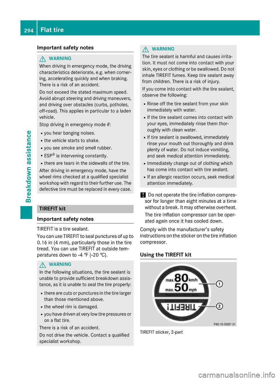
Using the TIREFIT kit TIREFIT sticker, 2-part294
Flat tireBreakdown assistance
Page 319 of 358
when adjusting the tire pressure
(Y
page 314).
i The actual values for tires are vehicle-
specific and may deviate from the values in
the illustration. Checking the tire pressures
Important safety notes Observe the notes on tire pressure
(Y
page 314).
Information on air pressure for the tires on
your vehicle can be found:
R on the vehicle's Tire and Loading Informa-
tion placard on the B-pillar
R on the tire pressure label on the fuel filler
flap
R in the "Tire pressure" section
Checking tire pressures manually To determine and set the correct tire pres-
sure, proceed as follows:
X Remove the valve cap of the tire that is to
be checked.
X Press the tire pressure gauge securely onto
the valve.
X Read the tire pressure and compare it with
the recommended value on the Tire and
Loading Information placard (Y page 314).
X If the tire pressure is too low, increase it to
the recommended value.
X If the tire pressure is too high, release air by
pressing down the metal pin in the valve.
Use the tip of a pen, for example. Then,
check the tire pressure again using the tire
pressure gauge.
X Screw the valve cap onto the valve.
X Repeat these steps for the other tires. Tire pressure loss warning system
(Canada only)
General notes While the vehicle is in motion, the tire pres-
sure loss warning system monitors the set
tire pressure using the rotational speed of the wheels. This enables the system to detect
significant pressure loss in a tire. If the speed
of rotation of a wheel changes as a result of a loss of pressure, a corresponding warning
message will appear in the multifunction dis- play.
You can recognize the tire pressure loss warn-
ing by the Run Flat Indicator Active Run Flat Indicator Active
Press 'OK' to Restart
Press 'OK' to Restart message which
appears in the Service
Servicemenu of the multi-
function display. Information on the message
display can be found in the "Restarting the tire
pressure loss warning system" section
(Y page 318).
Important safety notes The tire pressure warning system does not
warn you of an incorrectly set tire pressure.
Observe the notes on the recommended tire
pressure (Y page 314).
The tire pressure loss warning does not
replace the need to regularly check the tire
pressure. An even loss of pressure on several tires at the same time cannot be detected by
the tire pressure loss warning system.
The tire pressure monitor is not able to warn
you of a sudden loss of pressure, e.g. if the
tire is penetrated by a foreign object. In the
event of a sudden loss of pressure, bring the
vehicle to a halt by braking carefully. Avoid
abrupt steering maneuvers.
The function of the tire pressure loss warning system is limited or delayed if:
R snow chains are mounted on your vehicle's
tires.
R road conditions are wintry.
R you are driving on sand or gravel. Tire pressure
317Wheels and tires Z
Page 323 of 358
too low and must be corrected at the next
opportunity.
R If the Check
Check Tires
Tiresmessage appears in the
multifunction display, the tire pressure in
one or more tires has dropped significantly
and the tires must be checked.
R If the Warning Tire Malfunction Warning Tire Malfunction
appears in the multifunction display, the
tire pressure in one or more tires has drop- ped suddenly and the tires must be
checked.
Observe the instructions and safety notes in
the display messages in the "Tires" section
(Y page 236).
i If the wheel positions on the vehicle are
rotated, the tire pressures may be dis-
played for the wrong positions for a short
time. This is rectified after a few minutes of
driving, and the tire pressures are displayed for the correct positions.
Restarting the tire pressure monitor When you restart the tire pressure monitor, all
existing warning messages are deleted and
the warning lamps go out. The monitor uses
the currently set tire pressures as the refer-
ence values for monitoring. In most cases, the tire pressure monitor will automatically
detect the new reference values after you
have changed the tire pressure. However, you
can also define reference values manually as
described here. The tire pressure monitor
then monitors the new tire pressure values.
X Set the tire pressure to the value recom-
mended for the corresponding driving sit-
uation on the Tire and Loading Information placard on the driver's side
B-pillar (Y page 314).
Additional tire pressure values for different loads can also be found on the tire pressure
table on the inside of the fuel filler flap
(Y page 314).
X Make sure that the tire pressure is correct
on all four wheels. X
Make sure that the SmartKey is in position
2 in the ignition lock.
X Press the 0059or0065 button on the steer-
ing wheel to select the Service
Service menu.
X Press the 0063or0064 button to select
Tire Pressure Tire Pressure.
X Press the 0076button.
The multifunction display shows the cur-
rent tire pressure for the individual tires or
the Tire Tire pressure
pressure will
willbe
bedisplayed
displayed
after driving a few minutes
after driving a few minutes mes-
sage.
X Press the 0064button.
The Use Current Pressures as New
Use Current Pressures as New
Reference Values
Reference Values message appears in
the multifunction display.
If you wish to confirm the restart: X Press the 0076button.
The Tire
Tire Pressure
Pressure Monitor
MonitorRestarted
Restarted
message appears in the multifunction dis-
play.
After driving for a few minutes, the system checks whether the current tire pressures
are within the specified range. The new tire
pressures are then accepted as reference
values and monitored.
If you wish to cancel the restart:
X Press the 0038button.
The tire pressure values stored at the last
restart will continue to be monitored.
Radio type approval for the tire pres-
sure monitor Country Radio type approval number
USA FCC ID: MRXMW2433A
FCC ID: MRXGG4
FCC ID: MRXMC34MA4
Canada IC: 2546A-MW2433A
IC: 2546A-GG4
IC: 2546A-MC34MA4 Tire pressure
321Wheels and tires Z
Page 334 of 358

Traction
Traction is the result of friction between the
tires and the road surface.
Treadwear indicators
Narrow bars (tread wear bars) that are dis-
tributed over the tire tread. If the tire tread is level with the bars, the wear limit of 00CDin
(1.6 mm) has been reached.
Occupant distribution
The distribution of occupants in a vehicle at
their designated seating positions.
Total load limit
Rated cargo and luggage load plus
68 kilograms (150 lb) multiplied by the num-
ber of seats in the vehicle. Changing a wheel
Flat tire
The "Breakdown assistance" section
(Y page 292) contains information and notes
on how to deal with a flat tire. Information on driving with MOExtended tires in the event of
a flat tire can be found under "MOExtended
tires (tires with run-flat characteristics"
(Y page 293). Rotating the wheels
G
WARNING
Interchanging the front and rear wheels may
severely impair the driving characteristics if
the wheels or tires have different dimensions. The wheel brakes or suspension components
may also be damaged. There is a risk of acci-
dent.
Rotate front and rear wheels only if the wheels and tires are of the same dimensions.
! On vehicles equipped with a tire pressure
monitor, electronic components are loca-
ted in the wheel. Tire-mounting tools should not be used
near the valve. This could damage the elec-
tronic components.
Only have tires changed at a qualified spe-cialist workshop.
Always pay attention to the instructions and
safety notes when changing a wheel
(Y page 333).
The wear patterns on the front and rear tires
differ, depending on the operating conditions.
Rotate the wheels before a clear wear pattern has formed on the tires. Front tires typically
wear more on the shoulders and the rear tires in the center.
If your vehicle's tire configuration allows, you can rotate the wheels according to the inter-
vals in the tire manufacturer's warranty book
in your vehicle documents. If no warranty
book is available, the tires should be rotated
every 3,000 to 6,000 miles (5,000 to
10,000 km), or earlier if tire wear requires. Do not change the direction of wheel rotation.
Clean the contact surfaces of the wheel and
the brake disc thoroughly every time a wheel
is rotated. Check the tire pressure and, if nec- essary, restart the tire pressure loss warning
system or the tire pressure monitor. Direction of rotation
Tires with a specified direction of rotation
have additional benefits, e.g. if there is a risk of hydroplaning. You will only gain these ben-
efits if the correct direction of rotation is
maintained.
An arrow on the sidewall of the tire indicates
its correct direction of rotation. Storing wheels
Store wheels that are not being used in a cool, dry and preferably dark place. Protect the
tires from oil, grease, gasoline and diesel. 332
Changing a wheelWheels and tires
Page 336 of 358

Securing the vehicle on level ground
X On level ground: place chocks or other
suitable items under the front and rear of
the wheel that is diagonally opposite the
wheel you wish to change. Securing the vehicle on slight downhill gradients
X On light downhill gradients: place
chocks or other suitable items in front of
the wheels of the front and rear axle.
Raising the vehicle G
WARNING
If you do not position the jack correctly at the appropriate jacking point of the vehicle, the
jack could tip over with the vehicle raised.
There is a risk of injury.
Only position the jack at the appropriate jack-
ing point of the vehicle. The base of the jack
must be positioned vertically, directly under
the jacking point of the vehicle.
! The jack is designed exclusively for jack-
ing up the vehicle at the jacking points.
Otherwise, your vehicle could be damaged. The following must be observed when raising
the vehicle:
R to raise the vehicle, only use the vehicle-
specific jack that has been tested and
approved by Mercedes-Benz. If used incor-
rectly, the jack could tip over with the vehi-
cle raised.
R the jack is designed only to raise and hold
the vehicle for a short time while a wheel
is being changed. It is not suited for per-
forming maintenance work under the vehi- cle.
R avoid changing the wheel on uphill and
downhill slopes.
R before raising the vehicle, secure it from
rolling away by applying the parking brake
and inserting wheel chocks. Never disen-
gage the parking brake while the vehicle is raised.
R the jack must be placed on a firm, flat and
non-slip surface. On a loose surface, a
large, flat, load-bearing underlay must be
used. On a slippery surface, a non-slip
underlay must be used, e.g. rubber mats.
R do not use wooden blocks or similar
objects as a jack underlay. Otherwise, the
jack will not be able to achieve its load-
bearing capacity due to the restricted
height.
R make sure that the distance between the
underside of the tires and the ground does
not exceed 1.2 in (3 cm).
R never place your hands and feet under the
raised vehicle.
R do not lie under the vehicle.
R do not start the engine when the vehicle is
raised.
R do not open or close a door or the trunk lid
when the vehicle is raised.
R make sure that no persons are present in
the vehicle when the vehicle is raised. 334
Changing a wheelWheels and tires