2015 MERCEDES-BENZ S-CLASS COUPE rear view mirror
[x] Cancel search: rear view mirrorPage 231 of 417
This view assists you in estimating the dis-
tance to the vehicle behind you.
i This setting can also be selected as an
enlarged front view.
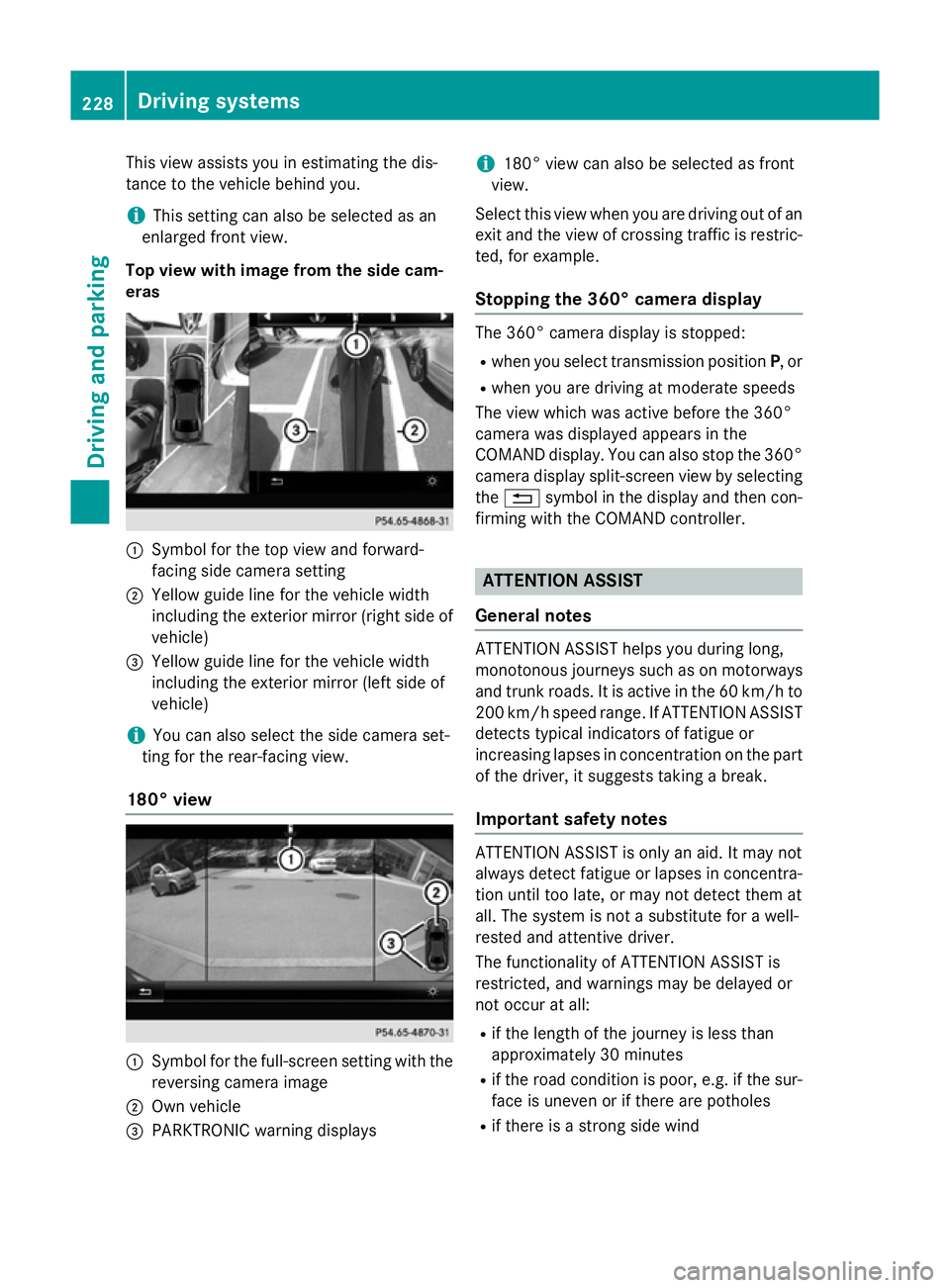
Top view with image from the side cam-
eras :
Symbol for the top view and forward-
facing side camera setting
; Yellow guide line for the vehicle width
including the exterior mirror (right side of vehicle)
= Yellow guide line for the vehicle width
including the exterior mirror (left side of
vehicle)
i You can also select the side camera set-
ting for the rear-facing view.
180° view :
Symbol for the full-screen setting with the
reversing camera image
; Own vehicle
= PARKTRONIC warning displays i
180° view can also be selected as front
view.
Select this view when you are driving out of an
exit and the view of crossing traffic is restric- ted, for example.
Stopping the 360° camera display The 360° camera display is stopped:
R
when you select transmission position P, or
R when you are driving at moderate speeds
The view which was active before the 360°
camera was displayed appears in the
COMAND display. You can also stop the 360° camera display split-screen view by selecting
the % symbol in the display and then con-
firming with the COMAND controller. ATTENTION ASSIST
General notes ATTENTION ASSIST helps you during long,
monotonous journeys such as on motorways and trunk roads. It is active in the 60 km/hto
200 km/h speed range. If ATTENTION ASSIST
detects typical indicators of fatigue or
increasing lapses in concentration on the part of the driver, it suggests taking a break.
Important safety notes ATTENTION ASSIST is only an aid. It may not
always detect fatigue or lapses in concentra-
tion until too late, or may not detect them at
all. The system is not a substitute for a well-
rested and attentive driver.
The functionality of ATTENTION ASSIST is
restricted, and warnings may be delayed or
not occur at all:
R if the length of the journey is less than
approximately 30 minutes
R if the road condition is poor, e.g. if the sur-
face is uneven or if there are potholes
R if there is a strong side wind 228
Driving systemsDriving and parking
Page 239 of 417

Problems with Night View Assist Plus
Problem
Possible causes/consequences and
M
MSolutions The picture quality of
Night View Assist Plus
has deteriorated. The windscreen is misted up on the inside.
X Fold down the camera cover (Y page 351).
X Demist the windscreen (Y page 144). The windscreen is iced up.
X De-ice the windscreen (Y page 144). The windscreen wipers are smearing the windscreen.
X Replace the wiper blades (Y page 134). The windscreen is smeared after the vehicle has been cleaned in a
car wash.
X Clean the windscreen (Y page 348). The windscreen has been damaged by stone impact in the cam-
era's field of vision.
X Replace the windscreen. The pedestrian and ani-
mal recognition is not
available. The infrared camera in the radiator grille is dirty.
X Use a soft cloth and water to clean the infrared camera. Driving Assistance Plus package
General notes The Driving Assistance PLUS package con-
sists of DISTRONIC PLUS (Y
page 194), Active
Blind Spot Assist (Y page 236) and Active
Lane Keeping Assist (Y page 239).
Active Blind Spot Assist General notes
Active Blind Spot Assist monitors the areas
on either side of the vehicle that are not visi-
ble to the driver with two lateral, rear-facing
radar sensors. A warning display in the exte-
rior mirrors draws your attention to vehicles
detected in the monitored area. If you then
switch on the corresponding turn signal to
change lanes, you will also receive a visual
and audible collision warning. If a risk of side impact is detected, corrective braking may
help you avoid a collision. Active Blind Spot
Assist evaluates the free space in the direc-
tion of travel and to the side before making a
course-correcting brake application. For this,Active Blind Spot Assist uses the forward-
facing radar sensors.
Active Blind Spot Assist supports you from a
speed of approximately 30 km/h.
Important safety notes
Active Blind Spot Assist is only an aid and is
not a substitute for attentive driving. 236
Driving systemsDriving and parking
Page 326 of 417
You can remove the cup holder and the rub-
ber mat for cleaning. Clean them with clean,
lukewarm water only.
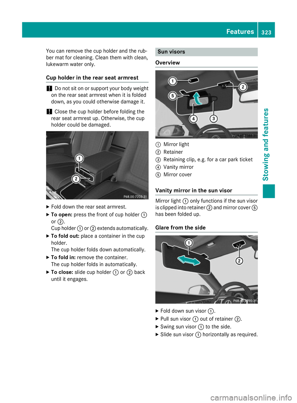
Cup holder in the rear seat armrest !
Do not sit on or support your body weight
on the rear seat armrest when it is folded
down, as you could otherwise damage it.
! Close the cup holder before folding the
rear seat armrest up. Otherwise, the cup
holder could be damaged. X
Fold down the rear seat armrest.
X To open: press the front of cup holder :
or ;.
Cup holder :or; extends automatically.
X To fold out: place a container in the cup
holder.
The cup holder folds down automatically.
X To fold in: remove the container.
The cup holder folds in automatically.
X To close: slide cup holder :or; back
until it engages. Sun visors
Overview :
Mirror light
; Retainer
= Retaining clip, e.g. for a car park ticket
? Vanity mirror
A Mirror cover
Vanity mirror in the sun visor Mirror light
:only functions if the sun visor
is clipped into retainer ;and mirror cover A
has been folded up.
Glare from the side X
Fold down sun visor :.
X Pull sun visor :out of retainer ;.
X Swing sun visor :to the side.
X Slide sun visor :horizontally as required. Features
323Stowing and features Z
Page 333 of 417
Garage door opener
General notes The HomeLink
®
garage door opener integra-
ted in the rear-view mirror allows you to oper- ate up to three different door and gate sys-
tems.
Once programmed, the integrated garage
door opener in the rear-view mirror will
assume the function of the garage door sys-
tem's remote control. Please also read the
operating instructions for the garage door
system.
When programming a garage door opener,
park the vehicle outside the garage. Do not
run the engine while programming.
The garage door opener is only available for
certain countries. Observe the legal require-
ments for each individual country.
The HomeLink ®
garage door opener is com-
patible with most European garage and gate
opener drives. More information on Home-
Link ®
and/or compatible products is availa-
ble:
R at a qualified specialist workshop
R via the HomeLink ®
Hotline
(0) 08000 466 354 65 or alternatively
+49 (0) 6838 907-277
R on the Internet at http://
www.homelink.com
Important safety notes G
WARNING
When you operate or program the garage door with the integrated garage door opener, per-
sons in the range of movement of the garage
door can become trapped or struck by the
garage door. There is a risk of injury.
When using the integrated garage door
opener, always make sure that nobody is
within the range of movement of the garage
door. G
WARNING
Combustion engines emit poisonous exhaust
gases such as carbon monoxide. Inhaling
these exhaust gases leads to poisoning. There is a risk of fatal injury. Therefore never leave
the engine running in enclosed spaces with-
out sufficient ventilation.
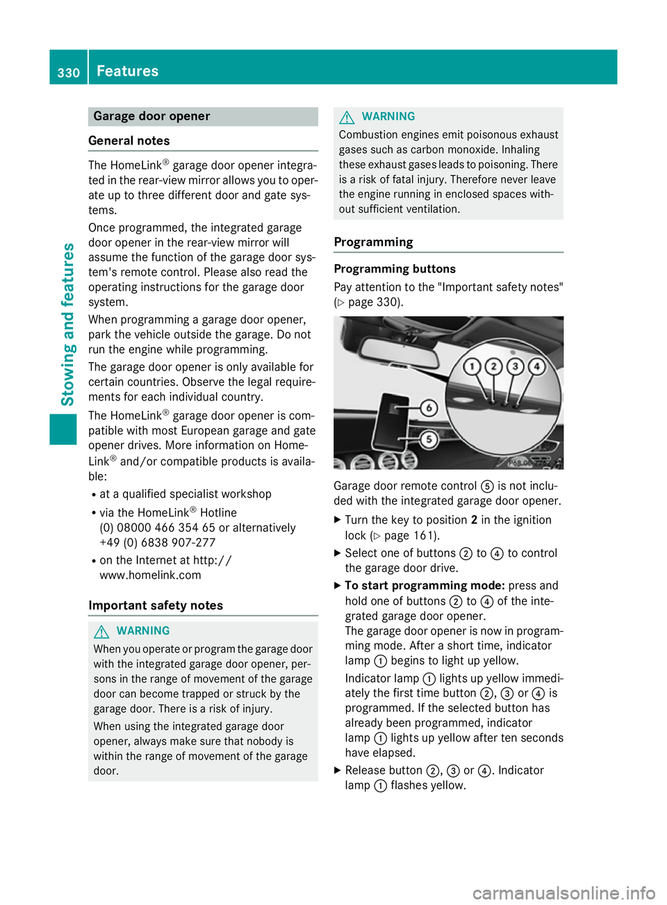
Programming Programming buttons
Pay attention to the "Important safety notes"
(Y page 330). Garage door remote control
Ais not inclu-
ded with the integrated garage door opener.
X Turn the key to position 2in the ignition
lock (Y page 161).
X Select one of buttons ;to? to control
the garage door drive.
X To start programming mode: press and
hold one of buttons ;to? of the inte-
grated garage door opener.
The garage door opener is now in program- ming mode. After a short time, indicator
lamp :begins to light up yellow.
Indicator lamp :lights up yellow immedi-
ately the first time button ;,=or? is
programmed. If the selected button has
already been programmed, indicator
lamp :lights up yellow after ten seconds
have elapsed.
X Release button ;,=or?. Indicator
lamp :flashes yellow. 330
FeaturesStowing and features
Page 334 of 417
X
To program the remote control: point
garage door remote control Atowards
buttons ;to? on the rear-view mirror at
a distance of 5 to 20 cm.
X Press and hold button Bon remote control
A until indicator lamp :lights up green.
When indicator lamp :lights up green:
programming is finished.
When indicator lamp :flashes green: pro-
gramming was successful. The next step is
to synchronise the rolling code
(Y page 331).
X Release button Bof remote control Aof
the garage door drive.
If indicator lamp :lights up red: repeat the
programming process for the correspond-
ing button on the rear-view mirror. When
doing so, vary the distance between remote control Aand the rear-view mirror.
The required distance between remote
control Aand the integrated garage door
opener depends on the garage door drive
system. Several attempts may be required.
You should test every position for at least
25 second sbefore trying another position.
Synchronising the rolling code
Observe the "Important safety notes"
(Y page 330).
If the garage door system uses a rolling code,
you will also have to synchronise the garage
door system with the integrated garage door
opener in the rear-view mirror. To do this you
will need to use the programming button on
the door drive control panel. The program-
ming button may be placed at different loca-
tions depending on the manufacturer. It is
usually located on the door drive unit on the
garage ceiling.
Familiarise yourself with the garage door
drive operating instructions, e.g. under "Pro-
gramming of additional remote controls",
before carrying out the following steps.
Your vehicle must be within range of the
garage door or gate opener drive. Make sure
that neither your vehicle nor any persons/ objects are present within the sweep of the
door or gate.
X Turn the key to position 2in the ignition
lock (Y page 161).
X Get out of the vehicle.
X Press the programming button on the door
drive unit.
Usually, you now have 30 seconds to ini-
tiate the next step.
X Get into the vehicle.
X Press previously programmed button ;,
= or? of the integrated garage door
opener until the door closes.
The rolling code synchronisation is then
complete.
Problems when programming
If you have problems when programming the
integrated garage door opener, please note
the following: R Check the transmitter frequency used by
garage door drive remote control Aand
whether it is supported. The transmitter
frequency can usually be found on the back
of the garage door drive remote control.
R Replace the batteries in garage door
remote control A. This increases the like-
lihood that garage door remote control A
will transmit a strong and precise signal to
the integrated garage door opener in the
rear-view mirror.
R When programming, hold remote control
A at varying distances and angles from the
button which you are programming. Try var- ious angles at a distance between 5and
30 cm or at the same angle but at varying
distances.
R If there is another remote control for the
same garage door drive, perform the pro-
gramming steps again using this remote
control. Before performing these steps,
make sure that new batteries have been
fitted in garage door drive remote control
A. Features
331Stowing and features Z
Page 335 of 417
R
Note that some remote controls transmit
only for a limited period (the indicator lamp
on the remote control goes out). Press but-ton Bon remote control Aagain before
transmission ends.
R Align the aerial cable of the garage door
opener unit. This can improve signal recep-
tion/transmission.
Opening or closing the garage door Once programmed, the integrated garage
door opener will assume the function of the
garage door system's remote control. Please
also read the operating instructions for the
garage door system.
X Turn the key to position 2in the ignition
lock (Y page 161).
X Press button ;,=or? which you have
programmed to operate the garage door.
Garage door system with a fixed code: indi-
cator lamp :lights up green.
Garage door system with a rolling code:
indicator lamp :flashes green.
The transmitter will transmit a signal for as long as the button is pressed. The trans-
mission is halted after a maximum of ten
seconds and indicator lamp :lights up
yellow.
X Press button ;,=or? again if neces-
sary.
Clearing the memory Make sure that you clear the memory of the
integrated garage door opener before selling
the vehicle.
X Turn the key to position 2in the ignition
lock (Y page 161).
X Press and hold buttons ;and ?.
The indicator lamp initially lights up yellow
and then green.
X Release buttons ;and ?.
The memory of the integrated garage door
opener in the rear-view mirror is cleared. Frequencies Europe
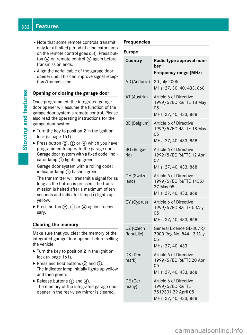
Country Radio type approval num-
ber
Frequency range (MHz)
AD (Andorra) 20 July 2005
MHz: 27, 30, 40, 433, 868
AT (Austria) Article 6 of Directive
1999/5/EC R&TTE 18 May
05
MHz: 27, 40, 433, 868
BE (Belgium) Article 6 of Directive
1999/5/EC R&TTE 18 May
05
MHz: 27, 40, 433, 868
BG (Bulga-
ria) Article 6 of Directive
1999/5/EC R&TTE 12 April
07
MHz: 27, 40, 433, 868 CH (Switzer-
land) Article 6 of Directive
1999/5/EC R&TTE 14357
27 May 05
MHz: 27, 40, 433, 868
CY (Cyprus) Article 6 of Directive
1999/5/EC R&TTE 5 May
05
MHz: 27, 40, 433, 868
CZ (Czech
Republic) General Licence GL-30/R/
2000 Reg No. 844 13 May
05
MHz: 27, 40, 433
DK (Den-
mark) Article 6 of Directive
1999/5/EC R&TTE 20 April
05
MHz: 27, 40, 433, 868 DE (Ger-
many) Article 6 of Directive
1999/5/EC R&TTE
7519301 29 April 05
MHz: 27, 40, 433, 868332
FeaturesStowing and features