2015 MERCEDES-BENZ M-Class stowage
[x] Cancel search: stowagePage 363 of 466

control. Please also read the operating
instructions for the garage door system.
When programing a garage door opener, park the vehicle outside the garage. Do not run the
engine while programing.
Certain garage door drives are incompatible
with the integrated garage door opener. If you have difficulty programing the integrated
garage door opener, contact an authorized
Mercedes-Benz Center.
Alternatively, you can call the following tele-
phone assistance services:
R USA: Mercedes-Benz Customer Assistance
Center at 1-800-FOR-MERCedes
R Canada: Customer Service at
1-800-387-0100
R HomeLink ®
hotline 1-800-355-3515 (free
of charge)
More information on HomeLink ®
and/or
compatible products is also available online
at http://www.homelink.com.
Notes on the declaration of conformity
(Y page 28).
USA: FCC ID: CB2HMIHL4
Canada: IC: 279B-HMIHL4
Important safety notes G
WARNING
When you operate or program the garage door with the integrated garage door opener, per-
sons in the range of movement of the garage
door can become trapped or struck by the
garage door. There is a risk of injury.
When using the integrated garage door
opener, always make sure that nobody is
within the range of movement of the garage
door. G
WARNING
Combustion engines emit poisonous exhaust
gases such as carbon monoxide. Inhaling
these exhaust gases leads to poisoning. There is a risk of fatal injury. Therefore never leave the engine running in enclosed spaces with-
out sufficient ventilation.
Programming Programing buttons
Pay attention to the "Important safety notes"
(Y page 361). Garage door remote control
0083is not inclu-
ded with the integrated garage door opener.
X Turn the SmartKey to position 2in the igni-
tion lock (Y page 157).
X Select one of buttons 0044to0085 to use to
control the garage door drive.
X To start programing mode: press and
hold one of buttons 0044to0085 on the inte-
grated garage door opener.
The garage door opener is now in program-
ing mode. After a short time, indicator
lamp 0043lights up yellow.
Indicator lamp 0043lights up yellow as soon
as button 0044,0087or0085 is programed for the
first time. If the selected button has already been programed, indicator lamp 0043will
only light up yellow after ten seconds have elapsed.
X Release button 0044,0087or0085. Indicator
lamp 0043flashes yellow.
X To program the remote control: point
garage door remote control 0083towards
buttons 0044to0085 on the rear-view mirror at
a distance of 2 to 8 inches (5 to 20 cm). Features
361Stowage and features Z
Page 364 of 466

X
Press and hold button 0084on remote control
0083 until indicator lamp 0043lights up green.
When indicator lamp 0043lights up green:
programing is finished.
When indicator lamp 0043flashes green: pro-
graming was successful. The next step is to
synchronize the rolling code.
X Release button 0084on remote control 0083for
the garage door drive system.
If indicator lamp 0043lights up red: repeat the
programing procedure for the correspond-
ing button on the rear-view mirror. When
doing so, vary the distance between remote control 0083and the rear-view mirror.
The required distance between remote
control 0083and the integrated garage door
opener depends on the garage door drive
system. Several attempts might be neces-
sary. You should test every position for at
least 25 seconds before trying another
position.
Synchronizing the rolling code
Pay attention to the "Important safety notes"
(Y page 361).
If the garage door system uses a rolling code, you will also have to synchronize the garage
door system with the integrated garage door
opener in the rear-view mirror. To do this you
will need to use the programing button on the
door drive control panel. The programing but- ton may be positioned at different locations
depending on the manufacturer. It is usually
located on the door drive unit on the garage
ceiling.
Familiarize yourself with the garage door
drive operating instructions, e.g. under "Pro-
graming of additional remote controls",
before carrying out the following steps.
Your vehicle must be within reach of the
garage door or gate opener drive. Make sure
that neither your vehicle nor any persons/
objects are present within the sweep of the
door or gate. X
Turn the SmartKey to position 2in the igni-
tion lock (Y page 157).
X Get out of the vehicle.
X Press the programing button on the door
drive unit.
Usually, you now have 30 seconds to ini-
tiate the next step.
X Get into the vehicle.
X Press previously programed button 0044,0087
or 0085 on the integrated garage door opener
until the door closes.
The rolling code synchronization is then
complete.
Notes on programing the remote control
Canadian radio frequency laws require a
"break" (or interruption) of the transmission
signals after broadcasting for a few seconds.
Therefore, these signals may not last long
enough for the integrated garage door
opener. The signal is not recognized during
programing. Comparable with Canadian law,
some U.S. garage door openers also feature a
"break".
Proceed as follows:
R if you live in Canada
R if you have difficulties programing the
garage door opener (regardless of where
you live) when using the programing steps.
X Press and hold one of buttons 0044to0085 on
the integrated garage door opener.
After a short time, indicator lamp 0043lights
up yellow.
X Release the button.
Indicator lamp 0043flashes yellow.
X Press button 0084of garage door remote
control 0083for two seconds, then release it
for two seconds.
X Press button 0084again for two seconds.
X Repeat this sequence on button 0084of
remote control 0083until indicator lamp 0043
lights up green.
When indicator lamp 0043lights up green:
programing is finished. 362
FeaturesStowage and features
Page 365 of 466

When indicator lamp
0043flashes green: pro-
graming was successful. The next step is to
synchronize the rolling code.
X Release button 0084of remote control 0083of
the garage door drive.
If indicator lamp 0043lights up red: repeat the
programing process for the corresponding
button on the rear-view mirror. When doing
so, vary the distance between remote con- trol 0083and the rear-view mirror.
The required distance between remote
control 0083and the integrated garage door
opener depends on the garage door drive
system. Several attempts might be neces-
sary. You should test every position for at
least 25 seconds before trying another
position.
Problems when programing
If you are experiencing problems programing
the integrated garage door opener on the
rear-view mirror, take note of the following
instructions:
R Check the transmitter frequency used by
garage door drive remote control 0083and
whether it is supported. The transmitter
frequency can usually be found on the back
of the garage door drive remote control.
The integrated garage door opener is com-
patible with devices that have units which
operate in the frequency range of 280 to
433 MHz.
R Replace the batteries in garage door
remote control 0083. This increases the like-
lihood that garage door remote control 0083
will transmit a strong and precise signal to the integrated garage door opener.
R When programing, hold remote control 0083
at varying distances and angles from the
button which you are programing. Try vari-
ous angles at a distance between 2and
12 inches (5to 30 cm) or at the same angle
but at varying distances.
R If another remote control is available for the
same garage door drive, repeat the same
programing steps with this remote control. Before performing these steps, make sure
that new batteries have been installed in
garage door drive remote control
0083.
R Note that some remote controls only trans-
mit for a limited amount of time (the indi-
cator lamp on the remote control goes out).
Press button 0084on remote control 0083again
before transmission ends.
R Align the antenna cable of the garage door
opener unit. This can improve signal recep-tion/transmission.
Opening/closing the garage door After it has been programed, the integrated
garage door opener performs the function of
the garage door system remote control.
Please also read the operating instructions
for the garage door system.
X Turn the SmartKey to position 2in the igni-
tion lock (Y page 157).
X Press button 0044,0087or0085 which you have
programed to operate the garage door.
Garage door system with a fixed code: indi-
cator lamp 0043lights up green.
Garage door system with a rolling code:
indicator lamp 0043flashes green.
The transmitter will transmit a signal as long
as the button is pressed. The transmission is halted after a maximum of ten seconds and
indicator lamp 0043lights up yellow. Press but-
ton 0044, 0087or0085 again if necessary.
Clearing the memory Make sure that you clear the memory of the
integrated garage door opener before selling
the vehicle.
X Turn the SmartKey to position 2in the igni-
tion lock (Y page 157).
X Press and hold buttons 0044and 0085.
The indicator lamp initially lights up yellow
and then green.
X Release buttons 0044and 0085.
The memory of the integrated garage door
opener in the rear-view mirror is cleared. Features
363Stowage and features Z
Page 366 of 466

Floormats
G
WARNING
Objects in the driver's footwell can restrict the pedal travel or obstruct a depressed pedal.
The operating and road safety of the vehicle is
jeopardized. There is a risk of an accident.
Make sure that all objects in the vehicle are
stowed correctly, and that they cannot enter
the driver's footwell. Install the floormats
securely and as specified in order to ensure
sufficient clearance for the pedals. Do not use loose floormats and do not place floormats on
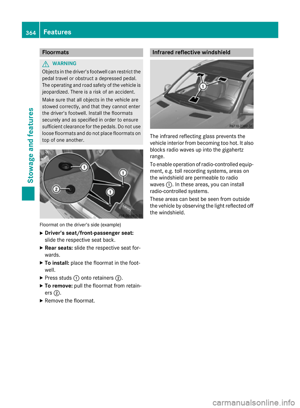
top of one another. Floormat on the driver's side (example)
X Driver's seat/front-passenger seat:
slide the respective seat back.
X Rear seats: slide the respective seat for-
wards.
X To install: place the floormat in the foot-
well.
X Press studs 0043onto retainers 0044.
X To remove: pull the floormat from retain-
ers 0044.
X Remove the floormat. Infrared reflective windshield
The infrared reflecting glass prevents the
vehicle interior from becoming too hot. It also
blocks radio waves up into the gigahertz
range.
To enable operation of radio-controlled equip- ment, e.g. toll recording systems, areas on
the windshield are permeable to radio
waves 0043. In these areas, you can install
radio-controlled systems.
These areas can best be seen from outside
the vehicle by observing the light reflected off
the windshield. 364
FeaturesStowage and featu
res
Page 387 of 466

inhale TIREFIT fumes. Keep tire sealant away
from children. There is a risk of injury.
If you come into contact with the tire sealant, observe the following:
R Rinse off the tire sealant from your skin
immediately with water.
R If the tire sealant comes into contact with
your eyes, immediately rinse them thor-
oughly with clean water.
R If tire sealant is swallowed, immediately
rinse your mouth out thoroughly and drink
plenty of water. Do not induce vomiting,
and seek medical attention immediately.
R Immediately change out of clothing which
has come into contact with tire sealant.
R If an allergic reaction occurs, seek medical
attention immediately.
! Do not operate the tire inflation compres-
sor for longer than eight minutes at a time
without a break. It may otherwise overheat.
The tire inflation compressor can be oper-
ated again once it has cooled down.
Comply with the manufacturer’s safety
instructions on the sticker on the tire inflation
compressor.
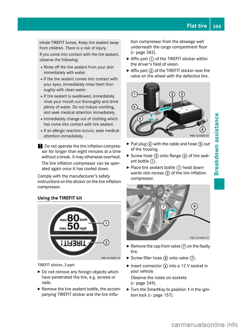
Using the TIREFIT kit TIREFIT sticker, 2-part
X Do not remove any foreign objects which
have penetrated the tire, e.g. screws or
nails.
X Remove the tire sealant bottle, the accom-
panying TIREFIT sticker and the tire infla- tion compressor from the stowage well
underneath the cargo compartment floor
(Y
page 382).
X Affix part 0043of the TIREFIT sticker within
the driver's field of vision.
X Affix part 0044of the TIREFIT sticker near the
valve on the wheel with the defective tire. X
Pull plug 0085with the cable and hose 0083out
of the housing.
X Screw hose 0083onto flange 0084of tire seal-
ant bottle 0043.
X Place tire sealant bottle 0043head down-
wards into recess 0044of the tire inflation
compressor. X
Remove the cap from valve 006Bon the faulty
tire.
X Screw filler hose 006Conto valve 006B.
X Insert connector 0085into a 12 V socket in
your vehicle.
Observe the notes on sockets
(Y page 349).
X Turn the SmartKey to position 1in the igni-
tion lock (Y page 157). Flat tire
385Breakdown assistance Z
Page 430 of 466

X
Clean the wheel and wheel hub contact
surfaces.
X Slide the wheel to be mounted onto the
alignment bolt and push it on.
X Tighten the wheel bolts until they are fin-
ger-tight.
X Unscrew the alignment bolt.
X Tighten the last wheel bolt until it is finger-
tight.
Lowering the vehicle G
WARNING
The wheels could work loose if the wheel nuts and bolts are not tightened to the specified
tightening torque. There is a risk of accident.
Have the tightening torque immediately
checked at a qualified specialist workshop
after a wheel is changed. X
Place the ratchet wrench onto the hexagon
nut of the jack so that the letters ABare
visible.
X Turn the ratchet wrench until the vehicle is
once again standing firmly on the ground.
X Place the jack to one side.
X Tighten the wheel bolts evenly in a cross-
wise pattern in the sequence indicated ( 0043
to 0083). The tightening torque must be
110 lb-ft (150 Nm).
X Turn the jack back to its initial position. X
Stow the jack and the rest of the tire-
change tool kit in the stowage well under
the cargo compartment floor again.
X Check the tire pressure of the newly moun-
ted wheel and adjust it if necessary.
Observe the recommended tire pressure
(Y page 404).
i Vehicles with tire pressure monitor: all
wheels mounted must be equipped with
functioning sensors. Wheel and tire combinations
General notes
! For safety reasons, Mercedes-Benz rec-
ommends that you only use tires and
wheels which have been approved by
Mercedes-Benz specifically for your vehi-
cle.
These tires have been specially adapted for
use with the control systems, such as ABS
or ESP ®
, and are marked as follows:
R MO = Mercedes-Benz Original
R MOE = Mercedes-Benz Original Extended
(tires featuring run-flat characteristics)
R MO1 = Mercedes-Benz Original (only cer-
tain AMG tires)
Mercedes-Benz Original Extended tires
may only be used on wheels that have been
specifically approved by Mercedes-Benz.
Only use tires, wheels or accessories tes-
ted and approved by Mercedes-Benz. Cer-
tain characteristics, e.g. handling, vehicle
noise emissions or fuel consumption, may
otherwise be adversely affected. In addi-
tion, when driving with a load, tire dimen-
sion variations could cause the tires to
come into contact with the bodywork and
axle components. This could result in dam- age to the tires or the vehicle.
Mercedes-Benz accepts no liability for
damage resulting from the use of tires,
wheels or accessories other than those tes-
ted and approved. 428
Wheel and tire combinationsWheels and tires
Page 443 of 466

!
AMG vehicles with "Minispare" emer-
gency spare wheel: use the "Minispare"
emergency spare wheel only on the rear
axle. If you mount the "Minispare" emer-
gency spare wheel on the front axle, this
could result in damage to the brake system.
If a tire on the front axle is defective, an
intact wheel from the rear axle must first be
replaced with the "Minispare" emergency
spare wheel. The defective wheel on the
front axle can then be replaced with the
intact wheel from the rear axle.
Make sure to note the placard on the
"Minispare" emergency spare wheel.
When using an emergency spare wheel or
spare wheel of a different size, you must not
exceed the maximum speed of 50 mph
(80 km/h).
Snow chains must not be mounted on emer-
gency spare wheels. General notes
Mounting the emergency spare wheel is
described under "Mounting a wheel"
(Y page 424).
You should regularly check the pressure of
the emergency spare wheel, particularly prior
to long trips, and correct the pressure as nec-
essary (Y page 404). The value on the wheel
or as given in the "Wheels and tires" section is
valid (Y page 443).
An emergency spare wheel may also be
mounted against the direction of rotation.
Observe the time restriction on use as well as
the speed limitation specified on the emer-
gency spare wheel.
Replace the tires after six years at the latest, regardless of wear. This also applies to the
emergency spare wheel.
i When you are driving with the collapsible
spare wheel mounted, the tire pressure
loss warning system or the tire pressure
monitor cannot function reliably. Only
restart the tire pressure loss warning sys- tem/the tire pressure monitor when the
damaged wheel has been replaced with a
new wheel.
Vehicles with tire pressure monitor:
after mounting an emergency spare wheel,
the system may still display the tire pres-
sure of the removed wheel for a few
minutes. The value displayed for the moun-
ted emergency spare wheel is not the same as the current tire pressure of the emer-
gency spare wheel. Removing the emergency spare wheel
Emergency spare wheel (example: vehicle without
lockable cargo compartment floor)
The "Minispare" emergency spare wheel can
be found in the stowage well under the cargo
compartment floor.
X Lift the cargo compartment floor up
(Y page 344).
X Vehicles with trailer tow hitch: remove
the ball coupling stowage tray
(Y page 258).
X Vehicles without a lockable cargo com-
partment floor: turn emergency spare
wheel retainer 0044counter-clockwise and
remove it.
X Remove "Minispare" emergency spare
wheel 0043. Emergency spare wheel
441Wheels and tires Z
Page 444 of 466

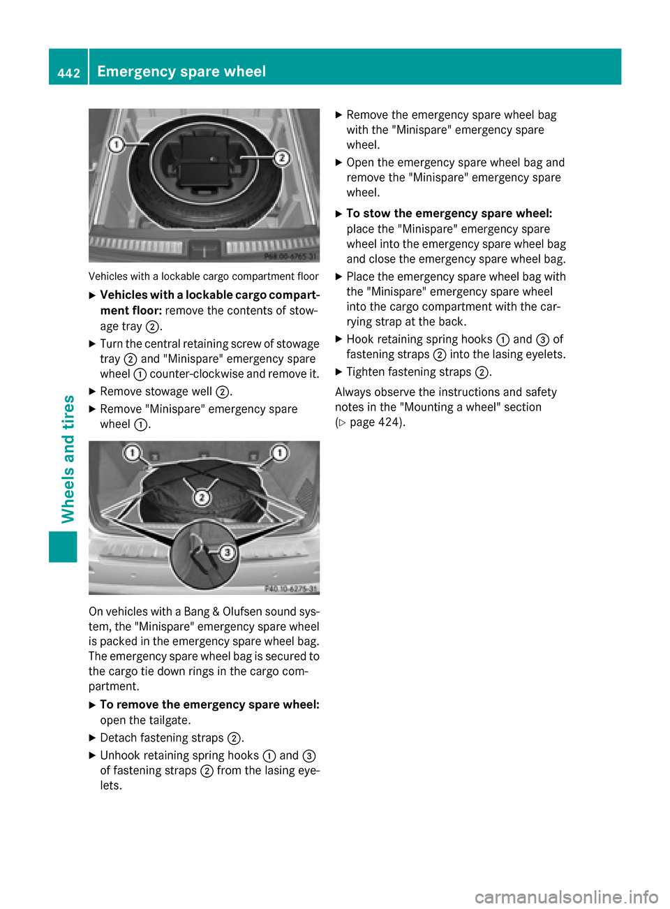
Vehicles with a lockable cargo compartment floor
X Vehicles with a lockable cargo compart-
ment floor: remove the contents of stow-
age tray 0044.
X Turn the central retaining screw of stowage
tray 0044and "Minispare" emergency spare
wheel 0043counter-clockwise and remove it.
X Remove stowage well 0044.
X Remove "Minispare" emergency spare
wheel 0043. On vehicles with a Bang & Olufsen sound sys-
tem, the "Minispare" emergency spare wheel
is packed in the emergency spare wheel bag. The emergency spare wheel bag is secured tothe cargo tie down rings in the cargo com-
partment.
X To remove the emergency spare wheel:
open the tailgate.
X Detach fastening straps 0044.
X Unhook retaining spring hooks 0043and 0087
of fastening straps 0044from the lasing eye-
lets. X
Remove the emergency spare wheel bag
with the "Minispare" emergency spare
wheel.
X Open the emergency spare wheel bag and
remove the "Minispare" emergency spare
wheel.
X To stow the emergency spare wheel:
place the "Minispare" emergency spare
wheel into the emergency spare wheel bag
and close the emergency spare wheel bag.
X Place the emergency spare wheel bag with
the "Minispare" emergency spare wheel
into the cargo compartment with the car-
rying strap at the back.
X Hook retaining spring hooks 0043and 0087of
fastening straps 0044into the lasing eyelets.
X Tighten fastening straps 0044.
Always observe the instructions and safety
notes in the "Mounting a wheel" section
(Y page 424). 442
Emergency spare wheelWheels and tires