2015 MERCEDES-BENZ GLE COUPE manual transmission
[x] Cancel search: manual transmissionPage 196 of 393
On steep uphill or downhill inclines or if there is
a malfunction, the transmission may also be
automatically shifted into position P.4MATIC
4MATIC ensures that all four wheels are perma-
nently driven. Together with ESP ®
and 4ETS, it
improves the traction of your vehicle whenever
a drive wheel spins due to insufficient grip.
If you fail to adapt your driving style, 4MATIC can
neither reduce the risk of an accident nor over-
ride the laws of physics. 4MATIC cannot take
account of road, weather and traffic conditions. 4MATIC is only an aid. You are responsible for
the distance to the vehicle in front, for vehicle
speed, for braking in good time and for staying in
lane.
! Never tow the vehicle with one axle raised.
This may damage the transfer case. Damage
of this sort is not covered by the Mercedes-
Benz implied warranty. All wheels must
remain either on the ground or be fully raised.
Observe the instructions for towing the vehi-
cle with all wheels in full contact with the
ground.
! A function or performance test should only
be carried out on a twin-axle dynamometer.
Before you operate the vehicle on such a
dynamometer, please consult a qualified
workshop. You could otherwise damage the
drive train or the brake system.
i In wintry driving conditions, the maximum
effect of 4MATIC can only be achieved if you
use winter tyres (M+S tyres), with snow
chains if necessary. DSR (Downhill Speed Regulation)
General notes DSR is an aid to assist you when driving down-
hill. It keeps the speed of travel at the speed
selected on the on-board computer. The steeper
the downhill gradient, the greater the DSR brak-
ing effect on the vehicle. When driving on flat
stretches of road or on an uphill gradient, the
DSR braking effect is minimal or non-existent.
DSR controls the vehicle’s speed when it is acti- vated and the transmission is in position D,Ror
N. By accelerating or braking, you can always drive at a higher or a lower speed than that set
on the on-board computer.
Important safety notes G
WARNING
If the speed driven and the set speed deviate and you activate DSR on a slippery road sur-
face, the wheels may lose traction. This
increases the risk of skidding and having an
accident.
Before switching DSR on, please take into
consideration the road surface and the differ-
ence between driving speed and the set
speed.
If you fail to adapt your driving style, DSR can
neither reduce the risk of accident nor override the laws of physics. DSR cannot take account ofroad, weather and traffic conditions. DSR is only
an aid. You are responsible for the distance to
the vehicle in front, for vehicle speed, for brak-
ing in good time and for staying in lane.
You are always responsible for keeping control
of the vehicle and for assessing whether the
downhill gradient can be managed. DSR may not
always be able to keep to the set speed, depend-
ing on road surface and tyre conditions. Select a set speed suitable for the prevailing conditions
and when necessary, apply the brakes manually.
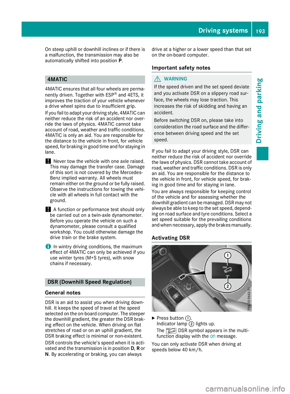
Activating DSR X
Press button :.
Indicator lamp ;lights up.
The à DSR symbol appears in the multi-
function display with the on onmessage.
You can only activate DSR when driving at
speeds below 40 km/h. Driving systems
193Driving and parking Z
Page 210 of 393
The emblem closes again when:
R you have finished the manoeuvring process
R you switch off the engine
R you open the boot
See the notes on cleaning (Y page 328).
For technical reasons, the emblem may
remain open briefly after the reversing cam-
era has been deactivated.
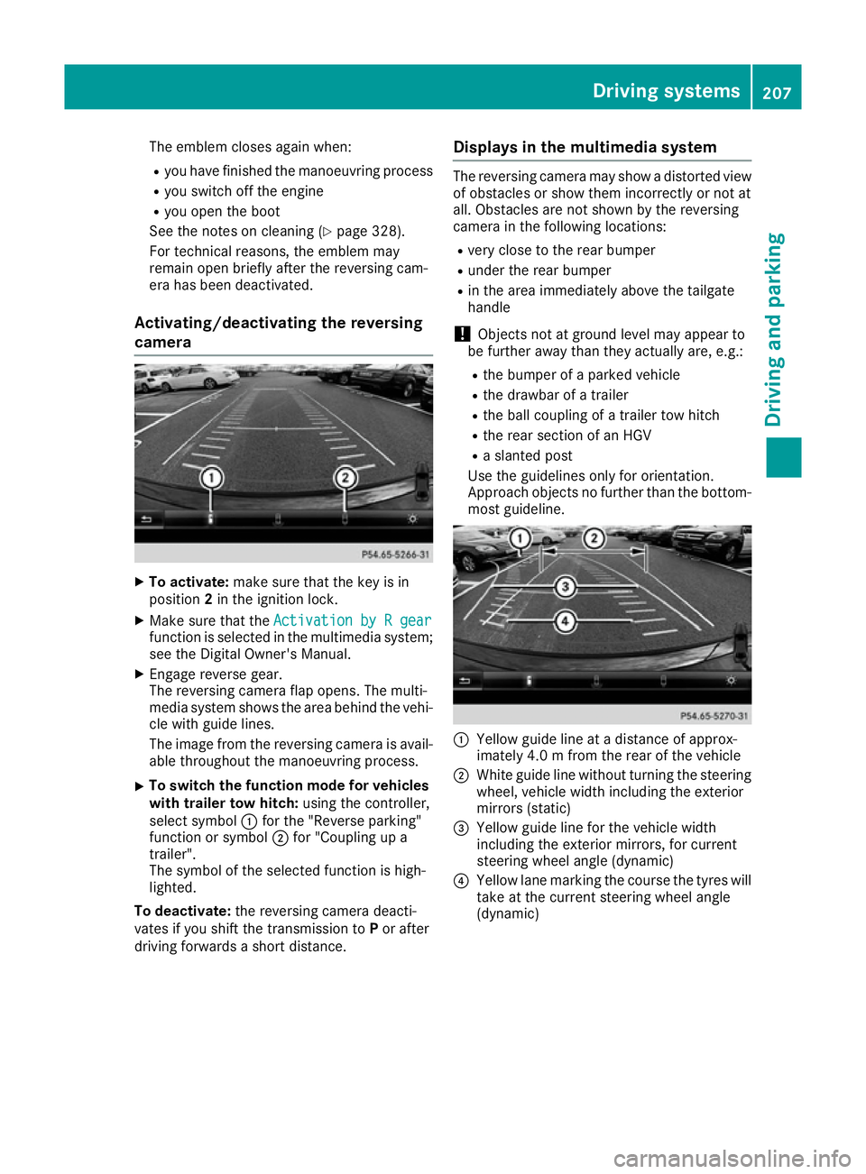
Activating/deactivating the reversing
camera X
To activate: make sure that the key is in
position 2in the ignition lock.
X Make sure that the Activation by R gear
Activation by R gear
function is selected in the multimedia system; see the Digital Owner's Manual.
X Engage reverse gear.
The reversing camera flap opens. The multi-
media system shows the area behind the vehi-
cle with guide lines.
The image from the reversing camera is avail-
able throughout the manoeuvring process.
X To switch the function mode for vehicles
with trailer tow hitch: using the controller,
select symbol :for the "Reverse parking"
function or symbol ;for "Coupling up a
trailer".
The symbol of the selected function is high-
lighted.
To deactivate: the reversing camera deacti-
vates if you shift the transmission to Por after
driving forwards a short distance. Displays in the multimedia system The reversing camera may show a distorted view
of obstacles or show them incorrectly or not at
all. Obstacles are not shown by the reversing
camera in the following locations:
R very close to the rear bumper
R under the rear bumper
R in the area immediately above the tailgate
handle
! Objects not at ground level may appear to
be further away than they actually are, e.g.:
R the bumper of a parked vehicle
R the drawbar of a trailer
R the ball coupling of a trailer tow hitch
R the rear section of an HGV
R a slanted post
Use the guidelines only for orientation.
Approach objects no further than the bottom- most guideline. :
Yellow guide line at a distance of approx-
imately 4.0 m from the rear of the vehicle
; White guide line without turning the steering
wheel, vehicle width including the exterior
mirrors (static)
= Yellow guide line for the vehicle width
including the exterior mirrors, for current
steering wheel angle (dynamic)
? Yellow lane marking the course the tyres will
take at the current steering wheel angle
(dynamic) Driving systems
207Driving and parking Z
Page 240 of 393
9
: Press and hold:
R
In the Audio Audio menu: selects a pre-
set list or a station list in the
desired frequency range, or
selects an audio track or video
scene using rapid scrolling
R In the Tel
Tel (Telephone) menu:
starts rapid scrolling if the phone
book is open a R
Confirms the selection or display
message
R In the Tel Tel(Telephone) menu:
switches to the telephone book
and starts dialling the selected
number % Press briefly:
R Back
R Switches off voice-operated navi-
gation or LINGUATRONIC
R Hides display messages or calls up
the last Trip Tripmenu function used
R Exits the telephone book/redial
memory % Press and hold:
R
Calls up the standard display in the
Trip
Trip menu Right control panel
~ R
Rejects or ends a call
R Exits the telephone book/redial
memory 6 R
Makes or accepts a call
R Switches to the redial memory W
X R
Adjusts the volume 8 R
Mute ? R
Switches on voice-operated navi-
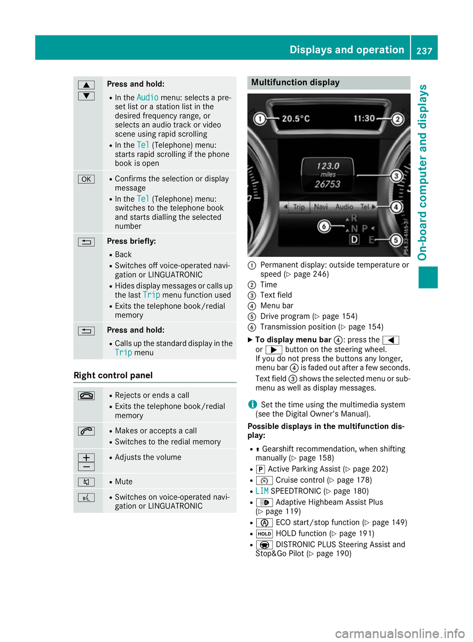
gation or LINGUATRONIC Multifunction display
:
Permanent display: outside temperature or
speed (Y page 246)
; Time
= Text field
? Menu bar
A Drive program (Y page 154)
B Transmission position (Y page 154)
X To display menu bar ?: press the=
or ; button on the steering wheel.
If you do not press the buttons any longer,
menu bar ?is faded out after a few seconds.
Text field =shows the selected menu or sub-
menu as well as display messages.
i Set the time using the multimedia system
(see the Digital Owner's Manual).
Possible displays in the multifunction dis-
play:
R ZGearshift recommendation, when shifting
manually (Y page 158)
R j Active Parking Assist (Y page 202)
R ¯ Cruise control (Y page 178)
R LIM
LIM SPEEDTRONIC (Y page 180)
R _ Adaptive Highbeam Assist Plus
(Y page 119)
R è ECO start/stop function (Y page 149)
R ë HOLD function (Y page 191)
R a DISTRONIC PLUS Steering Assist and
Stop&Go Pilot (Y page 190) Displays and operation
237On-board computer and displays Z
Page 253 of 393
AMG menu (Mercedes-AMG vehicles)
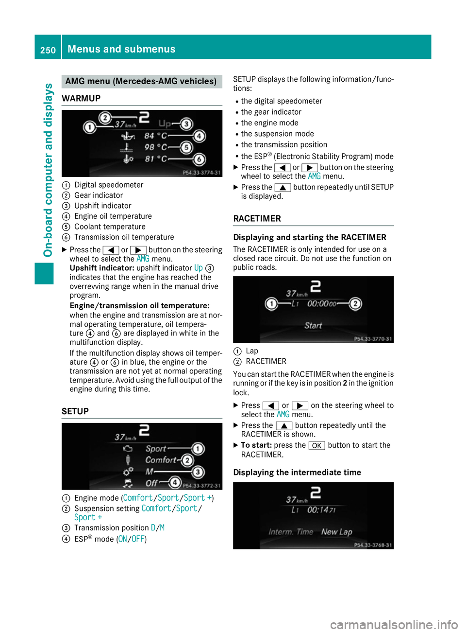
WARMUP :
Digital speedometer
; Gear indicator
= Upshift indicator
? Engine oil temperature
A Coolant temperature
B Transmission oil temperature
X Press the =or; button on the steering
wheel to select the AMG
AMGmenu.
Upshift indicator: upshift indicatorUp
Up=
indicates that the engine has reached the
overrevving range when in the manual drive
program.
Engine/transmission oil temperature:
when the engine and transmission are at nor- mal operating temperature, oil tempera-
ture ?and Bare displayed in white in the
multifunction display.
If the multifunction display shows oil temper- ature ?orB in blue, the engine or the
transmission are not yet at normal operating
temperature. Avoid using the full output of the
engine during this time.
SETUP :
Engine mode (Comfort Comfort/SportSport/Sport + Sport +)
; Suspension setting Comfort
Comfort/Sport
Sport/
Sport +
Sport +
= Transmission position D
D/M
M
? ESP ®
mode ( ON
ON/OFFOFF) SETUP displays the following information/func-
tions:
R the digital speedometer
R the gear indicator
R the engine mode
R the suspension mode
R the transmission position
R the ESP ®
(Electronic Stability Program) mode
X Press the =or; button on the steering
wheel to select the AMG
AMGmenu.
X Press the 9button repeatedly until SETUP
is displayed.
RACETIMER Displaying and starting the RACETIMER
The RACETIMER is only intended for use on a
closed race circuit. Do not use the function on
public roads. :
Lap
; RACETIMER
You can start the RACETIMER when the engine is running or if the key is in position 2in the ignition
lock.
X Press =or; on the steering wheel to
select the AMG AMGmenu.
X Press the 9button repeatedly until the
RACETIMER is shown.
X To start: press the abutton to start the
RACETIMER.
Displaying the intermediate time 250
Menus and sub
menusOn-board computer and displays
Page 260 of 393
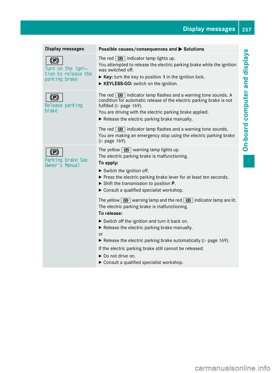
Display messages
Possible causes/consequences and
M
MSolutions !
Turn on the igni‐ Turn on the igni‐
tion tion
to
torelease
release the
the
parking brake
parking brake The red
!indicator lamp lights up.
You attempted to release the electric parking brake while the ignition
was switched off.
X Key: turn the key to position 1in the ignition lock.
X KEYLESS-GO: switch on the ignition. !
Release parking Release parking
brake brake The red
!indicator lamp flashes and a warning tone sounds. A
condition for automatic release of the electric parking brake is not
fulfilled (Y page 169).
You are driving with the electric parking brake applied.
X Release the electric parking brake manually. The red
!indicator lamp flashes and a warning tone sounds.
You are making an emergency stop using the electric parking brake
(Y page 169). !
Parking brake See Parking brake See
Owner's Manual Owner's Manual The yellow
!warning lamp lights up.
The electric parking brake is malfunctioning.
To apply:
X Switch the ignition off.
X Press the electric parking brake lever for at least ten seconds.
X Shift the transmission to position P.
X Consult a qualified specialist workshop. The yellow
!warning lamp and the red !indicator lamp are lit.
The electric parking brake is malfunctioning.
To release:
X Switch off the ignition and turn it back on.
X Release the electric parking brake manually.
or X Release the electric parking brake automatically (Y page 169).
If the electric parking brake still cannot be released: X Do not drive on.
X Consult a qualified specialist workshop. Display
messages
257On-board computer and displays Z
Page 261 of 393
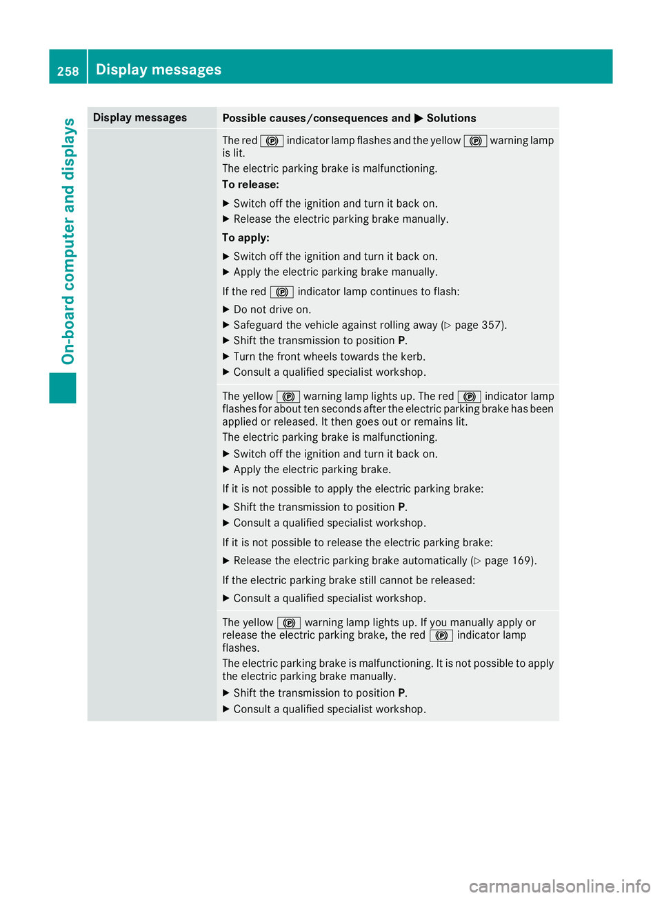
Display messages
Possible causes/consequences and
M
MSolutions The red
!indicator lamp flashes and the yellow !warning lamp
is lit.
The electric parking brake is malfunctioning.
To release:
X Switch off the ignition and turn it back on.
X Release the electric parking brake manually.
To apply: X Switch off the ignition and turn it back on.
X Apply the electric parking brake manually.
If the red !indicator lamp continues to flash:
X Do not drive on.
X Safeguard the vehicle against rolling away (Y page 357).
X Shift the transmission to position P.
X Turn the front wheels towards the kerb.
X Consult a qualified specialist workshop. The yellow
!warning lamp lights up. The red !indicator lamp
flashes for about ten seconds after the electric parking brake has been applied or released. It then goes out or remains lit.
The electric parking brake is malfunctioning.
X Switch off the ignition and turn it back on.
X Apply the electric parking brake.
If it is not possible to apply the electric parking brake:
X Shift the transmission to position P.
X Consult a qualified specialist workshop.
If it is not possible to release the electric parking brake:
X Release the electric parking brake automatically (Y page 169).
If the electric parking brake still cannot be released:
X Consult a qualified specialist workshop. The yellow
!warning lamp lights up. If you manually apply or
release the electric parking brake, the red !indicator lamp
flashes.
The electric parking brake is malfunctioning. It is not possible to apply
the electric parking brake manually.
X Shift the transmission to position P.
X Consult a qualified specialist workshop. 258
Display
messagesOn-board computer and displays
Page 262 of 393
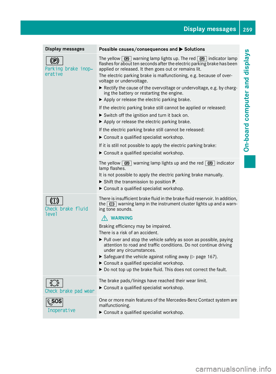
Display messages
Possible causes/consequences and
M
MSolutions !
Parking brake inop‐ Parking brake inop‐
erative erative The yellow
!warning lamp lights up. The red !indicator lamp
flashes for about ten seconds after the electric parking brake has been applied or released. It then goes out or remains lit.
The electric parking brake is malfunctioning, e.g. because of over-
voltage or undervoltage.
X Rectify the cause of the overvoltage or undervoltage, e.g. by charg-
ing the battery or restarting the engine.
X Apply or release the electric parking brake.
If the electric parking brake still cannot be applied or released: X Switch off the ignition and turn it back on.
X Apply or release the electric parking brake.
If the electric parking brake still cannot be released: X Consult a qualified specialist workshop.
If it is still not possible to apply the electric parking brake:
X Consult a qualified specialist workshop. The yellow
!warning lamp lights up and the red !indicator
lamp flashes.
It is not possible to apply the electric parking brake manually.
X Shift the transmission to position P.
X Consult a qualified specialist workshop. J
Check brake fluid Check brake fluid
level level There is insufficient brake fluid in the brake fluid reservoir. In addition,
the J warning lamp in the instrument cluster lights up and a warn-
ing tone sounds.
G WARNING
Braking efficiency may be impaired.
There is a risk of an accident.
X Pull over and stop the vehicle safely as soon as possible, paying
attention to road and traffic conditions. Do not continue driving
under any circumstances.
X Safeguard the vehicle against rolling away (Y page 167).
X Consult a qualified specialist workshop.
X Do not top up the brake fluid. This does not correct the fault. #
Check Check
brake
brakepad
padwear
wear The brake pads/linings have reached their wear limit.
X Consult a qualified specialist workshop. G
Inoperative
Inoperative One or more main features of the Mercedes-Benz Contact system are
malfunctioning.
X Consult a qualified specialist workshop. Display
messages
259On-board computer and displays Z
Page 360 of 393
The wear patterns on the front and rear tyres
differ depending on the operating conditions.
Interchange the wheels before a clear wear pat-
tern has formed on the tyres. Front tyres typi-
cally wear more on the shoulders and the rear
tyres in the centre.
On vehicles that have the same size front and
rear wheels, you can interchange the wheels
every 5,000 to 10,000 km depending on the
degree of tyre wear. Ensure that the direction of
rotation is maintained.
Clean the contact surfaces of the wheel and the
brake disc thoroughly every time a wheel is
interchanged. Check the tyre pressure and, if
necessary, restart the tyre pressure loss warn-
ing system or the tyre pressure monitor. Direction of rotation
Tyres with a specified direction of rotation have additional benefits, e.g. if there is a risk of aqua- planing. These advantages can only be gained if
the tyres are fitted corresponding to the direc-
tion of rotation.
An arrow on the sidewall of the tyre indicates its correct direction of rotation. Storing wheels
Store wheels that are not being used in a cool,
dry and preferably dark place. Protect the tyres
against oil, grease, petrol and diesel. Fitting a wheel
Preparing the vehicle X
Vehicles with an emergency spare wheel:
when fitting the emergency spare wheel in the
event of a flat tyre, observe the additional
notes on vehicle preparation under "Flat tyre"
(Y page 333).
X Stop the vehicle on solid, non-slippery and
level ground.
X Apply the electric parking brake manually.
X Unload heavy luggage.
X Move the front wheels to the straight-ahead
position.
X Shift the transmission to position P.X
Vehicles with the AIRMATIC package:
make sure that the normal vehicle level is
selected (Y
page 196).
X Switch off the engine.
X Vehicles without KEYLESS-GO: remove the
key from the ignition lock.
X Vehicles with KEYLESS-GO: open the driv-
er's door.
The on-board electronics now have status 0.
This is the same as the key having been
removed.
X Vehicles with KEYLESS-GO: remove the
Start/Stop button from the ignition lock
(Y page 146).
X If included in the vehicle equipment, remove
the tyre-change tool kit from the vehicle.
X Safeguard the vehicle against rolling away.
i Apart from certain country-specific varia-
tions, vehicles are not equipped with a tyre-
change tool kit. For information on which
tools are required to perform a wheel change
on your vehicle, consult a Mercedes-Benz
Service Centre.
Necessary tyre-changing tools may include,
for example:
R Jack
R Wheel chock
R Wheel wrench
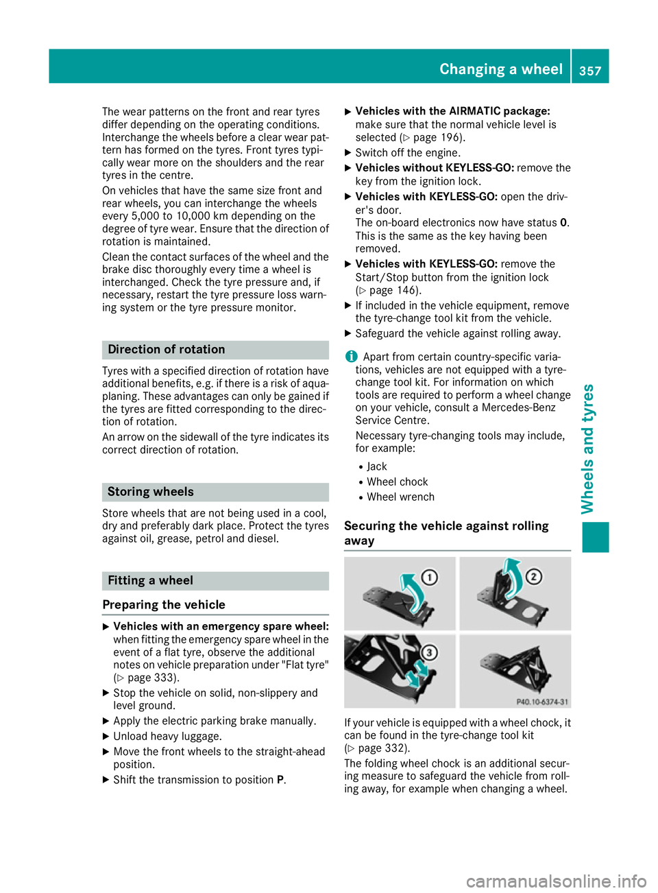
Securing the vehicle against rolling
away If your vehicle is equipped with a wheel chock, it
can be found in the tyre-change tool kit
(Y page 332).
The folding wheel chock is an additional secur-
ing measure to safeguard the vehicle from roll-
ing away, for example when changing a wheel. Changing a wheel
357Wheels and tyres Z