2015 MERCEDES-BENZ GLE COUPE engine
[x] Cancel search: enginePage 236 of 393
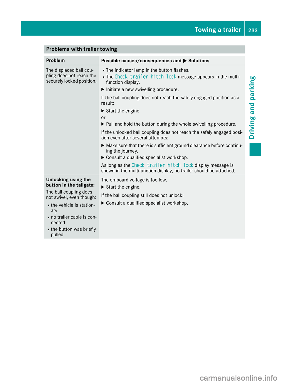
Problems with trailer towing
Problem
Possible causes/consequences and
M
MSolutions The displaced ball cou-
pling does not reach the
securely locked position. R
The indicator lamp in the button flashes.
R The Check trailer hitch lock Check trailer hitch lock message appears in the multi-
function display.
X Initiate a new swivelling procedure.
If the ball coupling does not reach the safely engaged position as a
result:
X Start the engine
or
X Pull and hold the button during the whole swivelling procedure.
If the unlocked ball coupling does not reach the safely engaged posi- tion even after several attempts:
X Make sure that there is sufficient ground clearance before continu-
ing the journey.
X Consult a qualified specialist workshop.
As long as the Check trailer hitch lock
Check trailer hitch lock display message is
shown in the multifunction display, no trailer should be attached. Unlocking using the
button in the tailgate:
The ball coupling does
not swivel, even though:
R
the vehicle is station-
ary
R no trailer cable is con-
nected
R the button was briefly
pulled The on-board voltage is too low.
X Start the engine.
If the ball coupling still does not unlock:
X Consult a qualified specialist workshop. Towing a trailer
233Driving and parking Z
Page 237 of 393
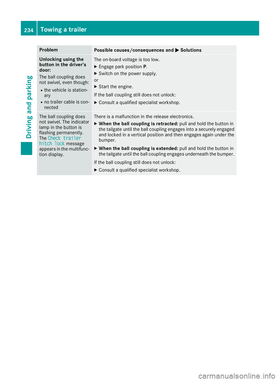
Problem
Possible causes/consequences and
M
MSolutions Unlocking using the
button in the driver's
door:
The ball coupling does
not swivel, even though:
R the vehicle is station-
ary
R no trailer cable is con-
nected The on-board voltage is too low.
X Engage park position P.
X Switch on the power supply.
or X Start the engine.
If the ball coupling still does not unlock: X Consult a qualified specialist workshop. The ball coupling does
not swivel. The indicator
lamp in the button is
flashing permanently.
The
Check trailer Check trailer
hitch lock
hitch lock message
appears in the multifunc- tion display. There is a malfunction in the release electronics.
X When the ball coupling is retracted: pull and hold the button in
the tailgate until the ball coupling engages into a securely engaged
and locked in a vertical position and then engages again under the
bumper.
X When the ball coupling is extended: pull and hold the button in
the tailgate until the ball coupling engages underneath the bumper.
If the ball coupling still does not unlock:
X Consult a qualified specialist workshop. 234
Towing a trailerDriving and parking
Page 238 of 393
Useful information
i This Owner's Manual describes all models,
series and optional equipment for your vehi-
cle that were available at the time of going to
press. National variations are possible. Note
that your vehicle may not be equipped with all
of the functions described. This is also the
case for systems and functions relevant to
safety.
i Read the information on qualified specialist
workshops: (Y page 25). Important safety notes
G
WARNING
Operating the integrated information systems and communications equipment in the vehicle
while driving will distract you from traffic con-
ditions. You could then lose control of the
vehicle. There is a risk of an accident.
Only operate these devices if road traffic con-
ditions permit. If you are unsure about the
surrounding conditions, pull over to a safe
location and make entries only while the vehi-
cle is stationary.
You must observe the legal requirements for the country in which you are currently driving whenoperating the on-board computer. G
WARNING
If the instrument cluster has failed or mal-
functioned, you may not recognise function
restrictions relevant to safety. The operating
safety of your vehicle may be impaired. There is a risk of an accident.
Drive on carefully. Have the vehicle checked
at a qualified specialist workshop immedi-
ately.
If the operating safety of your vehicle is
impaired, park the vehicle safely as soon as pos- sible. Contact a qualified specialist workshop.
The on-board computer only shows messages or warnings from certain systems in the multifunc-tion display. You should therefore make sure
your vehicle is operating safely at all times. For an overview, see the instrument cluster illus-
tration (Y page 29). Displays and operation
Instrument cluster lighting
The lighting in the instrument cluster, in the dis- plays and the controls in the vehicle interior can
be adjusted using the brightness control knob.
The brightness control knob is located on the
bottom left of the instrument cluster
(Y page 29).
X Turn the brightness control knob clockwise or
anti-clockwise.
If you turn the light switch to Ã,Tor
L, the brightness is dependent upon the
brightness of the ambient light.
i The light sensor in the instrument cluster
automatically controls the brightness of the
multifunction display.
In daylight, the displays in the instrument
cluster are not illuminated. Speedometer with segments
The speedometer is divided into segments only
on vehicles with DISTRONIC PLUS.
The segments in the speedometer indicate
which speed range is available.
R Variable SPEEDTRONIC activated
(Y page 180):
The segments light up from the start of the
scale to the selected limit speed.
R DISTRONIC PLUS activated (Y page 182):
One or two segments in the set speed range
light up.
R DISTRONIC PLUS detects a vehicle in front
moving more slowly than the stored speed:
The segments between the speed of the vehi- cle in front and the stored speed light up. Rev counter
! Do not drive in the overrevving range. Doing
so will damage the engine.
The red band in the rev counter indicates the
engine's overrevving range. Displays and operation
235On-board computer and displays Z
Page 239 of 393
The fuel supply is interrupted to protect the
engine when the red band is reached. Outside temperature display
You should pay special attention to road condi-
tions when temperatures are around freezing
point.
Bear in mind that the outside temperature dis-
play indicates the measured air temperature
and not the road surface temperature.
The outside temperature display is in the multi-
function display (Y page 237).
A change in the outside temperature is shown in the multifunction display after a delay. Coolant temperature gauge
G
WARNING
If you open the bonnet while the engine is
overheating or while there is a fire in the
engine compartment, you could come into
contact with hot gases or other leaking ser-
vice products. There is a danger of injury.
Allow an overheating engine to cool down
before opening the bonnet. If there is a fire in the engine compartment, leave the bonnet
closed and notify the fire brigade.
The coolant temperature gauge is in the instru-
ment cluster on the right-hand side (Y page 29).
Under normal operating conditions and with the specified coolant level, the coolant temperature
may rise to 120 †.
At high outside temperatures and when driving
uphill, the coolant temperature may rise to the
end of the scale. Operating the on-board computer
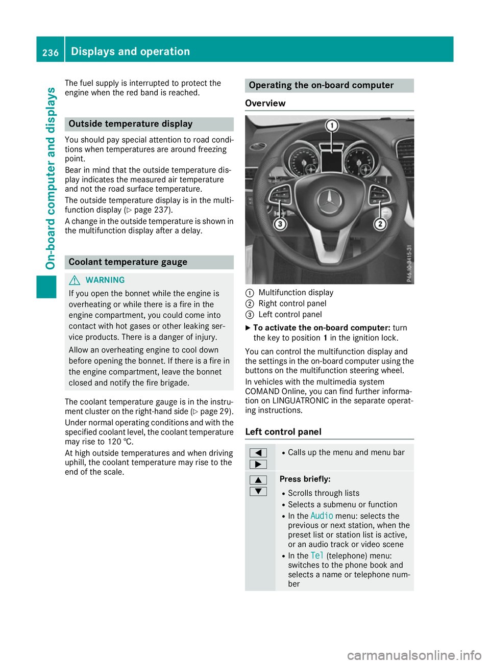
Overview :
Multifunction display
; Right control panel
= Left control panel
X To activate the on-board computer: turn
the key to position 1in the ignition lock.
You can control the multifunction display and
the settings in the on-board computer using the buttons on the multifunction steering wheel.
In vehicles with the multimedia system
COMAND Online, you can find further informa-
tion on LINGUATRONIC in the separate operat-
ing instructions.
Left control panel =
; R
Calls up the menu and menu bar 9
: Press briefly:
R Scrolls through lists
R Selects a submenu or function
R In the Audio Audio menu: selects the
previous or next station, when the preset list or station list is active,
or an audio track or video scene
R In the Tel Tel(telephone) menu:
switches to the phone book and
selects a name or telephone num-
ber 236
Displays and operationOn-board computer and displays
Page 242 of 393
If the ignition remains switched off for longer
than four hours, the ECO display will be auto-
matically reset.
Further information on the ECO display
(Y page 171).
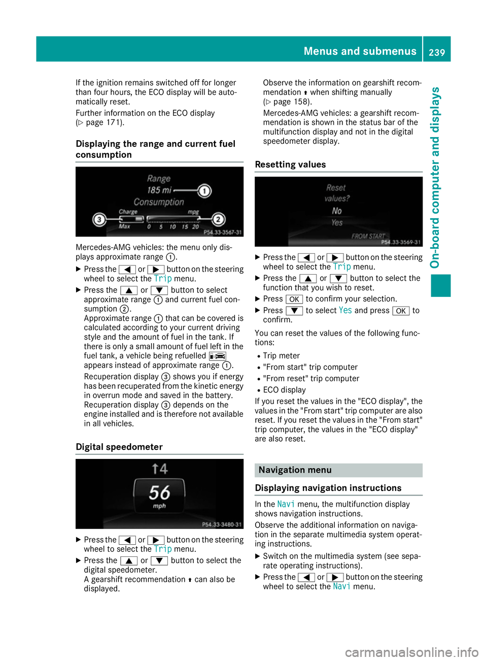
Displaying the range and current fuel
consumption Mercedes-AMG vehicles: the menu only dis-
plays approximate range
:.
X Press the =or; button on the steering
wheel to select the Trip
Trip menu.
X Press the 9or: button to select
approximate range :and current fuel con-
sumption ;.
Approximate range :that can be covered is
calculated according to your current driving
style and the amount of fuel in the tank. If
there is only a small amount of fuel left in the fuel tank, a vehicle being refuelled C
appears instead of approximate range :.
Recuperation display =shows you if energy
has been recuperated from the kinetic energy
in overrun mode and saved in the battery.
Recuperation display =depends on the
engine installed and is therefore not available in all vehicles.
Digital speedometer X
Press the =or; button on the steering
wheel to select the Trip
Trip menu.
X Press the 9or: button to select the
digital speedometer.
A gearshift recommendation Zcan also be
displayed. Observe the information on gearshift recom-
mendation
Zwhen shifting manually
(Y page 158).
Mercedes-AMG vehicles: a gearshift recom-
mendation is shown in the status bar of the
multifunction display and not in the digital
speedometer display.
Resetting values X
Press the =or; button on the steering
wheel to select the Trip Tripmenu.
X Press the 9or: button to select the
function that you wish to reset.
X Press ato confirm your selection.
X Press :to select Yes
Yesand press ato
confirm.
You can reset the values of the following func-
tions: R Trip meter
R "From start" trip computer
R "From reset" trip computer
R ECO display
If you reset the values in the "ECO display", the
values in the "From start" trip computer are also
reset. If you reset the values in the "From start" trip computer, the values in the "ECO display"
are also reset. Navigation menu
Displaying navigation instructions In the
Navi Navimenu, the multifunction display
shows navigation instructions.
Observe the additional information on naviga-
tion in the separate multimedia system operat-
ing instructions.
X Switch on the multimedia system (see sepa-
rate operating instructions).
X Press the =or; button on the steering
wheel to select the Navi
Navi menu. Menus and submenus
239On-board computer and displays Z
Page 253 of 393
AMG menu (Mercedes-AMG vehicles)
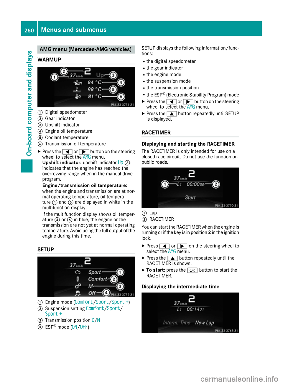
WARMUP :
Digital speedometer
; Gear indicator
= Upshift indicator
? Engine oil temperature
A Coolant temperature
B Transmission oil temperature
X Press the =or; button on the steering
wheel to select the AMG
AMGmenu.
Upshift indicator: upshift indicatorUp
Up=
indicates that the engine has reached the
overrevving range when in the manual drive
program.
Engine/transmission oil temperature:
when the engine and transmission are at nor- mal operating temperature, oil tempera-
ture ?and Bare displayed in white in the
multifunction display.
If the multifunction display shows oil temper- ature ?orB in blue, the engine or the
transmission are not yet at normal operating
temperature. Avoid using the full output of the
engine during this time.
SETUP :
Engine mode (Comfort Comfort/SportSport/Sport + Sport +)
; Suspension setting Comfort
Comfort/Sport
Sport/
Sport +
Sport +
= Transmission position D
D/M
M
? ESP ®
mode ( ON
ON/OFFOFF) SETUP displays the following information/func-
tions:
R the digital speedometer
R the gear indicator
R the engine mode
R the suspension mode
R the transmission position
R the ESP ®
(Electronic Stability Program) mode
X Press the =or; button on the steering
wheel to select the AMG
AMGmenu.
X Press the 9button repeatedly until SETUP
is displayed.
RACETIMER Displaying and starting the RACETIMER
The RACETIMER is only intended for use on a
closed race circuit. Do not use the function on
public roads. :
Lap
; RACETIMER
You can start the RACETIMER when the engine is running or if the key is in position 2in the ignition
lock.
X Press =or; on the steering wheel to
select the AMG AMGmenu.
X Press the 9button repeatedly until the
RACETIMER is shown.
X To start: press the abutton to start the
RACETIMER.
Displaying the intermediate time 250
Menus and sub
menusOn-board computer and displays
Page 254 of 393
X
Press the =or; button to select
Interm. Time
Interm. Time.
X Press ato confirm.
The intermediate time is displayed for five
seconds.
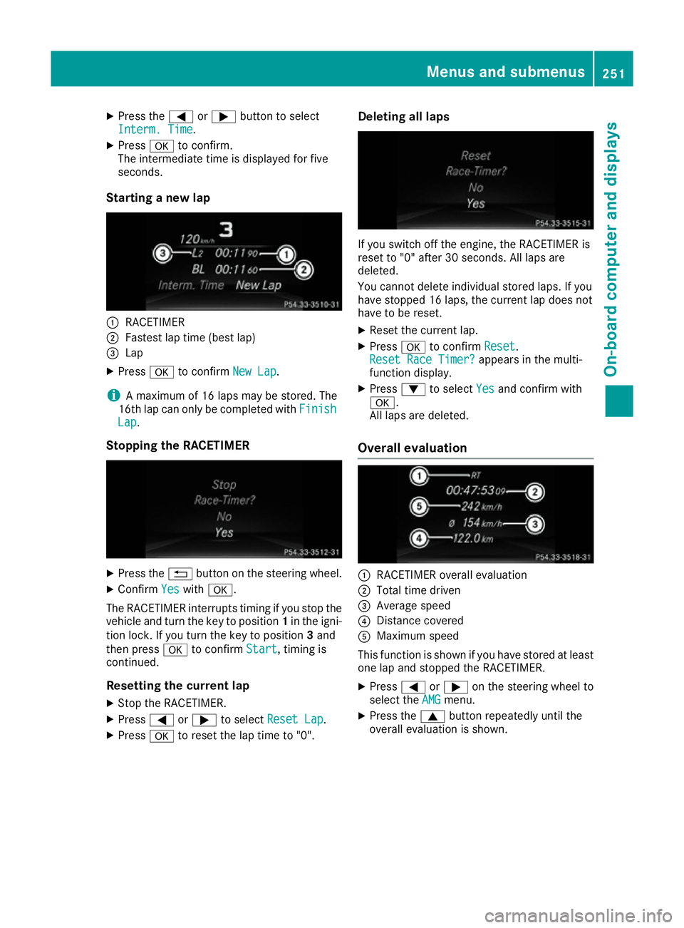
Starting a new lap :
RACETIMER
; Fastest lap time (best lap)
= Lap
X Press ato confirm New Lap
New Lap.
i A maximum of 16 laps may be stored. The
16th lap can only be completed with Finish
Finish
Lap
Lap.
Stopping the RACETIMER X
Press the %button on the steering wheel.
X Confirm Yes
Yes with a.
The RACETIMER interrupts timing if you stop the
vehicle and turn the key to position 1in the igni-
tion lock. If you turn the key to position 3and
then press ato confirm Start
Start, timing is
continued.
Resetting the current lap
X Stop the RACETIMER.
X Press =or; to select Reset Lap
Reset Lap.
X Press ato reset the lap time to "0". Deleting all laps If you switch off the engine, the RACETIMER is
reset to "0" after 30 seconds. All laps are
deleted.
You cannot delete individual stored laps. If you
have stopped 16 laps, the current lap does not
have to be reset.
X Reset the current lap.
X Press ato confirm Reset Reset.
Reset Race Timer?
Reset Race Timer? appears in the multi-
function display.
X Press :to select Yes
Yesand confirm with
a.
All laps are deleted.
Overall evaluation :
RACETIMER overall evaluation
; Total time driven
= Average speed
? Distance covered
A Maximum speed
This function is shown if you have stored at least one lap and stopped the RACETIMER.
X Press =or; on the steering wheel to
select the AMG AMGmenu.
X Press the 9button repeatedly until the
overall evaluation is shown. Menus and submenus
251On-board computer and displays Z
Page 262 of 393
Display messages
Possible causes/consequences and
M
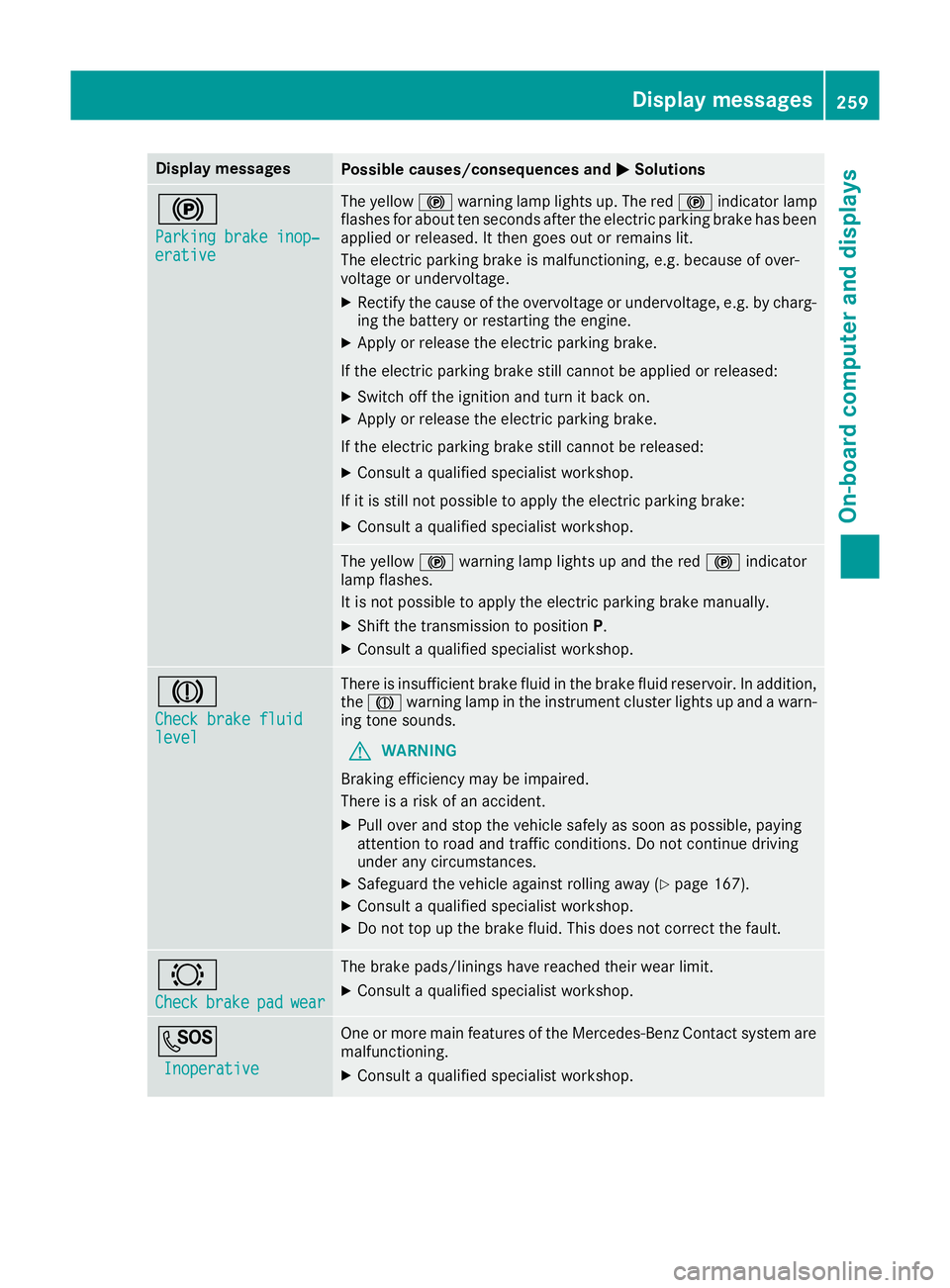
MSolutions !
Parking brake inop‐ Parking brake inop‐
erative erative The yellow
!warning lamp lights up. The red !indicator lamp
flashes for about ten seconds after the electric parking brake has been applied or released. It then goes out or remains lit.
The electric parking brake is malfunctioning, e.g. because of over-
voltage or undervoltage.
X Rectify the cause of the overvoltage or undervoltage, e.g. by charg-
ing the battery or restarting the engine.
X Apply or release the electric parking brake.
If the electric parking brake still cannot be applied or released: X Switch off the ignition and turn it back on.
X Apply or release the electric parking brake.
If the electric parking brake still cannot be released: X Consult a qualified specialist workshop.
If it is still not possible to apply the electric parking brake:
X Consult a qualified specialist workshop. The yellow
!warning lamp lights up and the red !indicator
lamp flashes.
It is not possible to apply the electric parking brake manually.
X Shift the transmission to position P.
X Consult a qualified specialist workshop. J
Check brake fluid Check brake fluid
level level There is insufficient brake fluid in the brake fluid reservoir. In addition,
the J warning lamp in the instrument cluster lights up and a warn-
ing tone sounds.
G WARNING
Braking efficiency may be impaired.
There is a risk of an accident.
X Pull over and stop the vehicle safely as soon as possible, paying
attention to road and traffic conditions. Do not continue driving
under any circumstances.
X Safeguard the vehicle against rolling away (Y page 167).
X Consult a qualified specialist workshop.
X Do not top up the brake fluid. This does not correct the fault. #
Check Check
brake
brakepad
padwear
wear The brake pads/linings have reached their wear limit.
X Consult a qualified specialist workshop. G
Inoperative
Inoperative One or more main features of the Mercedes-Benz Contact system are
malfunctioning.
X Consult a qualified specialist workshop. Display
messages
259On-board computer and displays Z