2015 MERCEDES-BENZ G-CLASS SUV change time
[x] Cancel search: change timePage 179 of 274

System menu overview
SystemTimeSPLITVIEWConsump- tionSeatDisplay off
Display settingsO Switches
the auto-
matic time
settingson/offOperates COMAND
functions
from thepassengersideCalls up the
fuel con-sumptiondisplayChanges
the driver/
front-passenger
seat set-tingsSwitches
off the dis-play
Text reader speedSets the
time zone
Voice-operated
control settingsSwitches to summertime
Rear view cameraManual
time setting
LanguageSets the time/dateformat
Favorites button
Activates/deacti-
vates Bluetooth®
Automatic volume adjustment
Imports/exports data
Resets COMAND
iDelete your
personal data
using this func-
tion, for example
before selling
your vehicle.
If equipped with the rear view camera: when the function is activated and COMAND is
switched on, the image from the rear view camera is automatically shown in the COMAND
display when reverse gear is engaged.
iIf the360°Cameramenu item is displayed,DisplayOffcan be called up underSystem.
COMAND operating system177
COMAND
Z
Page 194 of 274

Useful information
iThis Operator's Manual describes all
models and all standard and optional equip- ment of your vehicle available at the time of
publication of the Operator's Manual.
Country-specific differences are possible.
Please note that your vehicle may not be
equipped with all features described. This
also applies to safety-related systems and
functions.
iRead the information on qualified special-
ist workshops: ( Ypage 28).
Loading guidelines
GWARNING
If objects, luggage or loads are not secured or
not secured sufficiently, they could slip, tip
over or be flung around and thereby hit vehicle
occupants. There is a risk of injury, particu-
larly in the event of sudden braking or a sud-
den change in direction.
Always store objects so that they cannot be
flung around. Secure objects, luggage or
loads against slipping or tipping before the
journey.
GWARNING
If you distribute the load unevenly in the vehi- cle, the handling as well as the steering and
braking characteristics are severely affected.
There is a risk of an accident.
Distribute the load evenly in the vehicle.
Secure the load to prevent it from slipping.
GWARNING
The exhaust tail pipe and tail pipe trim can
become very hot. If you come into contact
with these parts of the vehicle, you could burn
yourself. There is a risk of injury.
Always be particularly careful around the
exhaust tail pipe and the tail pipe trim. Allow
these components to cool down before touch-
ing them.
GWARNING
Combustion engines emit poisonous exhaust
gases such as carbon monoxide. If the tail-
gate/rear door is open when the engine is
running, particularly if the vehicle is moving,
exhaust fumes could enter the passenger
compartment. There is a risk of poisoning.
Turn off the engine before opening the tail-
gate/rear door. Never drive off with the tail-
gate/rear door open.
Driving, braking and steering characteristics
change depending on:
R type of load
R weight
R the center of gravity of the load
You should therefore load your vehicle as
shown in the illustrations.
The gross vehicle weight (GVW) is the vehicle
weight including fuel, vehicle tool kit, spare
wheel, accessories installed, vehicle occu-
pants and luggage/load.
Do not exceed the load limit or permitted
gross vehicle weight rating (GVWR) for your
vehicle. The gross load limit and the GVWR
are specified on the vehicle identification
plate on the B-pillar of the driver's door( Y page 258).
The load must also be distributed so that the weight on each axle never exceeds the grossaxle weight rating (GAWR) for the front and
rear axles. The specifications for GVWR and
GAWR are on the vehicle identification plate
on the B-pillar of the driver's door( Y page 258).
192Loading guidelines
Stowage and features
Page 212 of 274

Maintaining the time-dependent service schedule:X Before disconnecting the battery, note
down the service due date displayed.
or X After reconnecting the battery, subtract
the battery disconnection periods from the
service date shown on the display.
iThe service interval display should not be
confused with the 4engine oil level dis-
play.
The symbol and the letter indicate which type
of service is due: ¯ Minor service
A
±Major serviceB
The ASSYST service interval display does not
take into account any periods of time during
which the battery is disconnected.
Hiding a service message
X To hide the service message, press the % back button on the multifunction
steering wheel ( Ypage 35).
Displaying service messages
Use the buttons on the multifunction steering
wheel.
X Switch on the ignition.
X Press =or; to select the standard
display menu on the steering wheel
( Y page 147).
X Press 9or: to select the service
interval display. The ¯ or± service symbol and the
service due date are displayed.
Points to remember
The specified maintenance interval takes only the normal operation of the vehicle into
account. Under arduous operating conditions
or increased load on the vehicle, mainte-
nance work must be carried out more fre-
quently, for example: R regular city driving with frequent intermedi-
ate stops
R if the vehicle is primarily used to travel
short distances
R use in mountainous terrain or on poor road
surfaces
R if the engine is often left idling for long peri-
ods
Under these or similar conditions, have, for
example, the air filter, engine oil and oil filter
replaced or changed more frequently. Under
arduous operating conditions, the tires must
be checked more often. Further information
can be obtained at a qualified specialist work- shop, e.g. an authorized Mercedes-Benz Cen-
ter.
Fuel/water separator
HEnvironmental note
Dispose of service products in an environ-
mentally responsible manner.
!If you continue driving without having the
fuel/water separator serviced, this could
cause damage to the engine. Any resulting
damage is not covered by the warranty.
If the fuel/water separator needs servicing,
the following message appears in the multi-
function display:
You will also hear a brief warning tone.
210Maintenance
Maintenance and care
Page 216 of 274

Useful information
iThis Operator's Manual describes all
models and all standard and optional equip- ment of your vehicle available at the time of
publication of the Operator's Manual.
Country-specific differences are possible.
Please note that your vehicle may not be
equipped with all features described. This
also applies to safety-related systems and
functions.
iRead the information on qualified special-
ist workshops: ( Ypage 28).
Where will I find...?
Warning triangle
Setting up the warning triangle
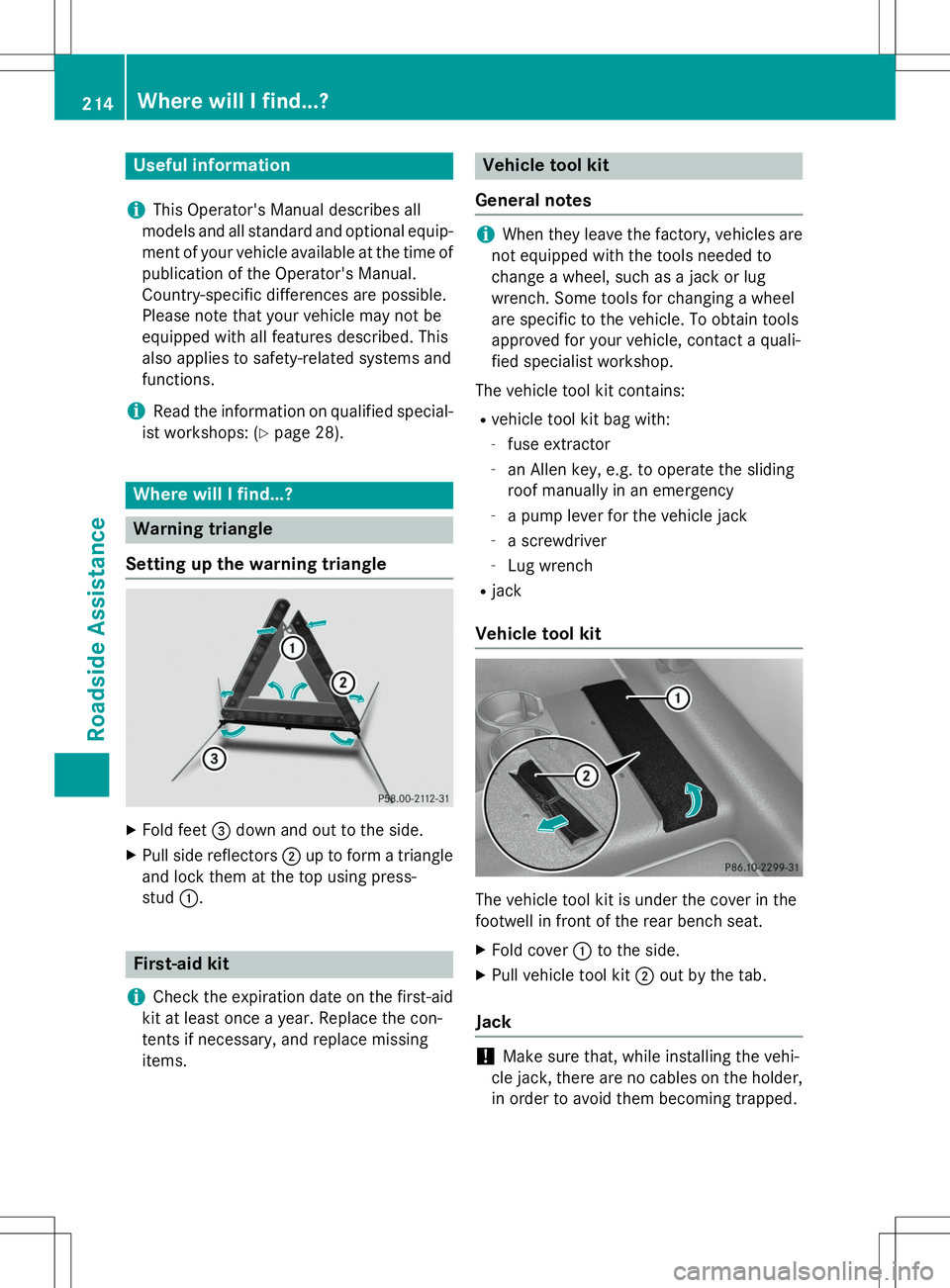
X Fold feet =down and out to the side.
X Pull side reflectors ;up to form a triangle
and lock them at the top using press- stud :.
First-aid kit
iCheck the expiration date on the first-aid
kit at least once a year. Replace the con-
tents if necessary, and replace missing
items.
Vehicle tool kit
General notes
iWhen they leave the factory, vehicles are
not equipped with the tools needed to
change a wheel, such as a jack or lug
wrench. Some tools for changing a wheel
are specific to the vehicle. To obtain tools
approved for your vehicle, contact a quali-
fied specialist workshop.
The vehicle tool kit contains: R vehicle tool kit bag with:
- fuse extractor
- an Allen key, e.g. to operate the sliding
roof manually in an emergency
- a pump lever for the vehicle jack
- a screwdriver
- Lug wrench
R jack
Vehicle tool kit
The vehicle tool kit is under the cover in the
footwell in front of the rear bench seat.
X Fold cover :to the side.
X Pull vehicle tool kit ;out by the tab.
Jack
!Make sure that, while installing the vehi-
cle jack, there are no cables on the holder, in order to avoid them becoming trapped.
214Where will I find...?
Roadside Assistance
Page 240 of 274

the multifunction display, the tire pressurein one or more tires has dropped suddenly
and the tires must be checked.
iIf the wheel positions on the vehicle are
rotated, the tire pressures may be dis-
played for the wrong positions for a short
time. This is rectified after a few minutes of driving, and the tire pressures are displayed
for the correct positions.
Restarting the tire pressure monitor
When you restart the tire pressure monitor, all existing warning messages are deleted and
the warning lamps go out. The monitor uses
the currently set tire pressures as the refer-
ence values for monitoring. In most cases, the
tire pressure monitor will automatically
detect the new reference values after you
have changed the tire pressure. However, you
can also define reference values manually as described here.
X Set the tire pressure to the value recom-
mended for the corresponding driving sit-
uation on the Tire and Loading Information
placard on the driver's side
B-pillar ( Ypage 232).
Additional tire pressure values for different loads can also be found on the tire pressure table on the inside of the fuel filler flap( Y page 232).
X Make sure that the tire pressure is correct
on all four wheels.
X Make sure that the SmartKey is in position
2 in the ignition lock ( Ypage 103).
X Press the =or; button on the steer-
ing wheel to select the
Serv.menu.
X Press the 9or: button to select
Tire Pressure.
X Press the abutton.
The multifunction display shows the cur-
rent tire pressure for the individual tires or
the
Tirepressurewillbedisplayed
after driving a few minutesmes-
sage.
X Press the :button.
The
Use Current Pressures as New
Reference Valuesmessage appears in
the multifunction display.
If you wish to confirm the restart:
X Press the abutton.
The
Tire Press. Monitor Restarted
message appears in the multifunction dis-
play.
After driving for a few minutes, the system
checks whether the current tire pressures
are within the specified range. The new tire
pressures are then accepted as reference
values and monitored.
If you wish to cancel the restart: X Press the %button.
The tire pressure values stored at the last
restart will continue to be monitored.
Loading the vehicle
Instruction labels for tires and loads
GWARNING
Overloaded tires can overheat, causing a
blowout. Overloaded tires can also impair the steering and driving characteristics and lead
to brake failure. There is a risk of accident.
Observe the load rating of the tires. The load
rating must be at least half of the GAWR of
your vehicle. Never overload the tires by
exceeding the maximum load.
238Loading the vehicle
Wheels and tires
Page 253 of 274

every 3,000 to 6,000 miles
(5,000 to 10,000 km), or earlier if tire wear
requires. Do not change the direction of
wheel rotation.
Clean the contact surfaces of the wheel and
the brake disc thoroughly every time a wheel
is rotated. Check the tire pressure and reac-
tivate the tire pressure monitor ( Ypage 235)
if necessary.
Direction of rotation
Tires with a specified direction of rotation
have additional benefits, e.g. if there is a risk
of hydroplaning. You will only gain these ben-
efits if the correct direction of rotation isobserved.
An arrow on the sidewall of the tire indicates
its correct direction of rotation.
You may mount the spare wheel against the
direction of rotation. Adhere to the time
restriction on use as well as the speed limi-
tation specified on the spare wheel.
Storing wheels
Store tires that are not being used in a cool,
dry and preferably dark place. Protect the
tires from oil, grease, gasoline and diesel.
Mounting a wheel
Preparing the vehicle
GWARNING
When you remove the spare wheel from the
spare wheel bracket, the vehicle’s weight dis- tribution changes. If the vehicle is already
raised, the jack could tip over. There is a risk
of injury.
Remove the spare wheel from the spare wheel
bracket before lifting the vehicle.
X Prepare the vehicle as described (Y page 216). X
Remove the vehicle tool kit and the jack(Y page 214).
X Secure the vehicle to prevent it from rolling
away.
X Remove the spare wheel from the spare
wheel bracket ( Ypage 215).
iVehicles without a spare wheel or emer-
gency spare wheel are not equipped with a tire-change tool kit at the factory. For more
information on which tools are required to
perform a wheel change on your vehicle
e.g. lug wrench or jack, consult an author-
ized Mercedes-Benz Center.
Securing the vehicle to prevent it from
rolling away
X On level ground: place chocks or other
suitable items under the front and rear of
the wheel that is diagonally opposite the
wheel you wish to change.
X On downhill gradients: place chocks or
other suitable items in front of the wheels
of the front and rear axle.
Raising the vehicle
GWARNING
If you do not position the jack correctly at the appropriate jacking point of the vehicle, the
jack could tip over with the vehicle raised.
There is a risk of injury.
Only position the jack at the appropriate jack-
ing point of the vehicle. The base of the jack
must be positioned vertically, directly under
the jacking point of the vehicle.
!The jack is designed exclusively for jack-
ing up the vehicle at the jacking points.
Otherwise, your vehicle could be damaged.
The following must be observed when raising
the vehicle:
R To raise the vehicle, only use the vehicle-
specific jack that has been tested and
approved by Mercedes-Benz. If used incor-
Changing a wheel251
Wheels and tires
Z
Page 254 of 274

rectly, the jack could tip over with the vehi-cle raised.
R The jack is designed only to raise and hold
the vehicle for a short time while a wheel
is being changed. It is not suited for per-
forming maintenance work under the vehi-
cle.
R Avoid changing the wheel on uphill and
downhill slopes.
R Before raising the vehicle, secure it from
rolling away by applying the parking brake
and inserting wheel chocks. Never disen-
gage the parking brake while the vehicle is
raised.
R The jack must be placed on a firm, flat and
non-slip surface. On a loose surface, a
large, load-bearing underlay must be used.
On a slippery surface, a non-slip underlay
must be used, e.g. rubber mats.
R Do not use wooden blocks or similar
objects as a jack underlay. Otherwise, the
jack will not be able to achieve its load-
bearing capacity due to the restricted
height.
R Make sure that the distance between the
underside of the tires and the ground does
not exceed 1.2 in (3 cm).
R Never place your hands and feet under the
raised vehicle.
R Never lie under the raised vehicle.
R Never start the engine when the vehicle is
raised.
R Never open or close a door or the tailgate
when the vehicle is raised.
R Make sure that no persons are present in
the vehicle when the vehicle is raised.
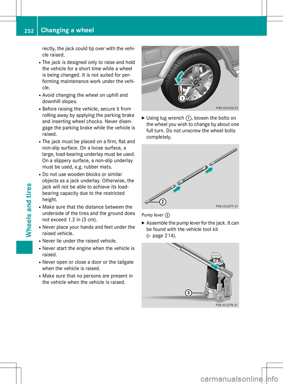
XUsing lug wrench :, loosen the bolts on
the wheel you wish to change by about one full turn. Do not unscrew the wheel bolts
completely.
Pump lever ;
X
Assemble the pump lever for the jack. It can
be found with the vehicle tool kit ( Y page 214).
252Changing a wheel
Wheels and tires