2015 MERCEDES-BENZ E-CLASS ESTATE rear view mirror
[x] Cancel search: rear view mirrorPage 141 of 497
harmful and causes irritation. It must not
come into contact with your skin, eyes, res-
piratory organs or clothing or be swallowed.
There is arisk of injury.
If you come into contact with electrolyte,
observe the following:
R immediately rinse off electrolyte from your
skin with water.
R immediately and thoroughly rinse electro-
lyte out of eyes using clean water.
R if electrolyte is swallowed, immediately
rinse out your mouth thoroughly. Do not
induce vomiting.
R if electrolyte comes into contact with skin
or eyes or is swallowed, seek medical atten-
tion immediately.
R immediately change out of clothing that has
been in contact with electrolyte.
R if an allergic reaction occurs, seek medical
attention immediately.
The rear-view mirror and the exterior mirror
on the driver's side automatically go into anti- dazzle mode if the following conditionsa re
met simultaneously:
R the ignition is switched on and
R incident light from headlamps strikes the
sensor in the rear-view mirror
The mirrors do not dip if reverse gear is
engaged or if the interior lighting is switched
on. Parking position of the exterior mirror
on the front-passenger side
Setting and storing the parking position Using reverse gear
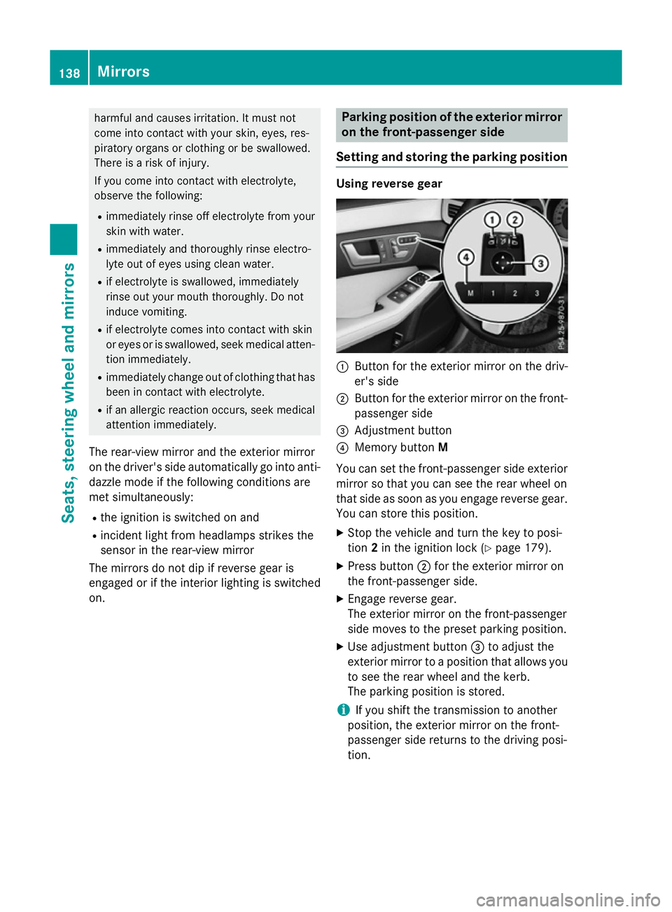
:
Button for the exterior mirror on the driv-
er's side
; Button for the exterior mirror on the front-
passenger side
= Adjustment button
? Memory button M
You can set the front-passenger side exterior
mirror so that you can see the rear wheel on
that side as soon as you engage reverse gear.
You can store this position.
X Stop the vehicle and turn the key to posi-
tion 2in the ignition lock (Y page 179).
X Press button ;for the exterior mirror on
the front-passenger side.
X Engage reverse gear.
The exterior mirror on the front-passenger
side moves to the preset parking position.
X Use adjustment button =to adjust the
exterior mirror to aposition that allowsy ou
to see the rear wheel and the kerb.
The parking position is stored.
i If you shift the transmission to another
position, the exterior mirror on the front-
passenger side returns to the driving posi-
tion. 138
MirrorsSeats, steering wheela
nd mirrors
Page 247 of 497
Once you have exited the parking space com-
pletely,t he steering wheel is moved to the
straight-ahead position. You hear atone and
the Park Assist switched off
Park Assist switched off message
appears in the multifunction display. You will
then have to steer and merge into traffic on
your own. PARKTRONIC is still available. You
can take over the steering before the vehicle has exited the parking space completely. This
is useful,f or example when you recognise
that it is already possibletop ull out of the
parking space.
Cancelling Active Parking Assist You can cancel Active Parking Assist at any
time.
X Stop the movement of the multifunction
steering wheel or steer yourself.
Active Parking Assist will be cancelled at
once. The Park Assist cancelled
Park Assist cancelled mes-
sage appears in the multifunction display
and you hear atone.
or X Press the PARKTRONIC button on the
centre console (Y page 237).
PARKTRONIC is switched off and Active
Parking Assist is immediately cancelled.
The Park Assist cancelled
Park Assist cancelled message
appears in the multifunction displaya nd
you hear atone.
Active Parking Assist is cancelled automati-
cally if:
R the transmission is shifted too early
R transmission position Pis selected
R parking using Active Parking Assist is no
longer possible
R you are driving faster than 10 km/h
R aw heel spins and ESP ®
intervenes or fails.
In such cases the ÷warning lamp lights
up in the instrument cluster.
Aw arning tone sounds. The parking symbol
disappears and the multifunction display
shows the Park Assist cancelled Park Assist cancelled mes-
sage. When Active Parking Assist is cancelled, you
must steer and brake againy
ourself.
Vehiclesw ith automatic transmission: if a
system malfunction occurs, the vehicle is
braked to astandstill. To drive on, depress the
accelerator pedal again.
Towing atrailer For vehicles with
atrailer tow hitch, the min-
imum length for parking spaces is slightly
increased.
If you have attached atrailer to your vehicle,
you should not use Active Parking Assist.
Once the electrical connection is established between your vehicle and the trailer, Active
Parking Assist is no longer available.
PARKTRONIC is deactivated for the rear area. Reversing camera
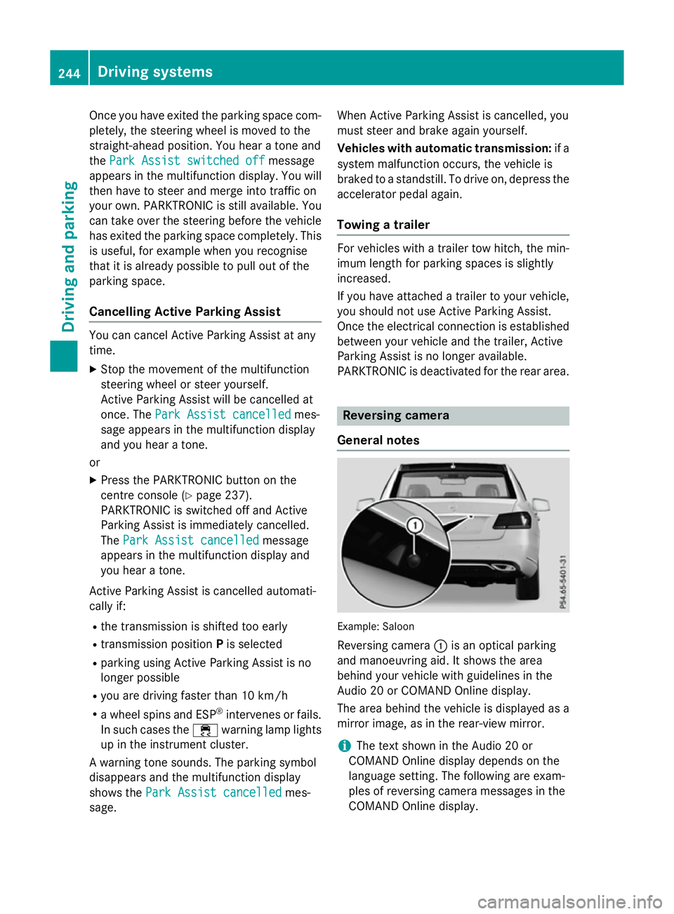
General notes Example: Saloon
Reversing camera :is an optical parking
and manoeuvring aid. It shows the area
behind your vehicle with guidelines in the
Audio 20 or COMAND Online display.
The area behind the vehicle is displayed as a
mirror image, as in the rear-view mirror.
i The text shown in the Audio 20 or
COMAND Online displayd epends on the
language setting. The following are exam-
ples of reversing camera messages in the
COMAND Online display. 244
Driving systemsDriving and parking
Page 252 of 497
X
Select symbol ?using the controller.
The "Coupling up atrailer" function is selec-
ted. The distance specifications now only
appl ytoo bjects tha tare at the same level
as the ball coupling.
X Revers ecarefully ,making sure tha ttrailer
drawbar locating aid ;points approx-
imatel yinthe direction of traile rdrawbar
=.
X Revers ecarefully unti ltraile rdrawbar =
reaches the red guid eline.
The distance between the traile rdrawbar
and the red guid elineisn ow approximately
0.30 m.
X Couple up the trailer (Y page 267).
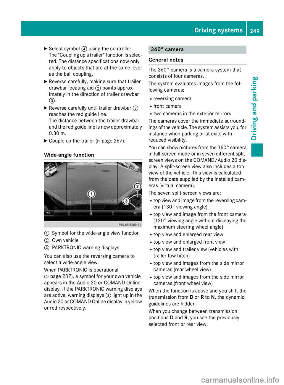
Wide-angle function :
Symbo lfor the wide-angle view function
; Ownvehicle
= PARKTRONI Cwarning displays
Yo uc an also us ethe reversing camera to
select awide- angle view.
When PARKTRONI Cisoperational
(Y page 237), asym bolfor your ow nvehicle
appear sinthe Audio 20 or COMAND Online
display. If the PARKTRONI Cwarning displays
ar ea ctive, warning displays =ligh tupint he
Audio 20 or COMAND Online displa yinyellow
or red respectively. 360° camera
General notes Th
e3 60° camera is acamera syste mthat
consists of fou rcameras.
Th es ysteme valuate simages fromt he fol-
lowing cameras:
R reversing camera
R front camera
R two camera sinthe exterior mirrors
Th ec amera scove rthe immediate surround-
ing soft he vehicle. Th esystema ssis ts you, for
instanc ewhenp arking or at exits with
reduced visibility.
Yo uc an sho wpictures fro mthe 360° camera
in full-screen mod eorinseven different split-
screen view sonthe COMAND/Audio 20 dis-
play .As plit-screen view also includes atop
view of the vehicle. This view is calculated
fro mt he data supplied by the installe dcam-
era s(virtual camera).
Th es even split-screen view sare:
R top view and imag efromt he reversing cam-
era (130° viewing angle)
R top view and imag efromt he front camera
(130° viewing angle without displaying the maximum steering whee langle)
R top view and enlarge drearv iew
R top view and enlarge dfront view
R top view and trailer view (vehicle swith
trailer tow hitch)
R top view and images fro mthe side mirror
camera s(rear whee lview)
R top view and images fro mthe side mirror
camera s(front whee lview)
When the functio nisa ctive and yo ushift the
transmission from Dor Rto N,t he dynamic
guideline sarehidden.
When yo uchange between transmission
positions Dand R,y ou seet he previously
selected front or rea rview. Driving systems
249Driving andparking Z
Page 254 of 497
X
Press the Øbutton in the centre con-
sole.
The vehicle menu appears.
X Select 360° camera
360° camera and press7to con-
firm.
The following appears depending on
whether transmission position Dor Ris
selected:
R as plit-screen with top view and the
image from the frontc amera or
R as plit-screen with top view and the
image from the reversin gcamera
Activating the 360° camera using
reverse gear You can show images from the 360° camera
automatically by engaging reverse gear.
X Make sure that the key is in position 2in the
ignition lock.
X Make sure that the ActivationbyR
Activatio nbyR
gear
gear function is selected in COMAND
Online/Audio 20 (see the separate
COMAND Online/Audio 20 operating
instructions).
X To show the 360° camera image: engage
reverse gear.
The area behind the vehicle is shown in the
COMAND/Audio 20 display in split-screen
mode. You see the top view of the vehicle
and the image from the reversin gcamera.
Selecting the split-screen and full
screen displays Switching between split screen views
X To switch to the line with the vehicle icons:
slide 5the controller.
X To select one of the vehicle icons: turn
3 the controller.
X To switch to 180° view
180° view: turn3 the
controller to select 180° view 180° viewand press
7 to confirm.
i The
180° view
180° view option is only availabl ein
the following views: R
Top view with image from the reversing
camera
R Top view with image from the frontc am-
era
Displays in the COMAND/Audio 20 dis-
play Important safety notes
The camera system may show
adistorted
view of obstacles or show them incorrectly or
not at all. Obstacles are not shown by the
system in the following locations:
R under the fronta nd rear bumpers
R very close to the fronta nd rear bumpers
R in the area immediately above the tailgate
handle/boot lid handle
R very close to the exterior mirrors
R in the transitional areas between the vari-
ous cameras in the virtual top view
! Objects not at ground level may appear to
be further away than they actually are, e.g.:
R the bumper of aparked vehicle
R the drawbar of atrailer
R the ball coupling of atrailer tow hitch
R the rear section of an HGV
R as lanted post
Use the guidelines only for orientation.
Approach object snofurther than the bot-
tom-most guideline. Driving systems
251Driving and parking Z
Page 255 of 497
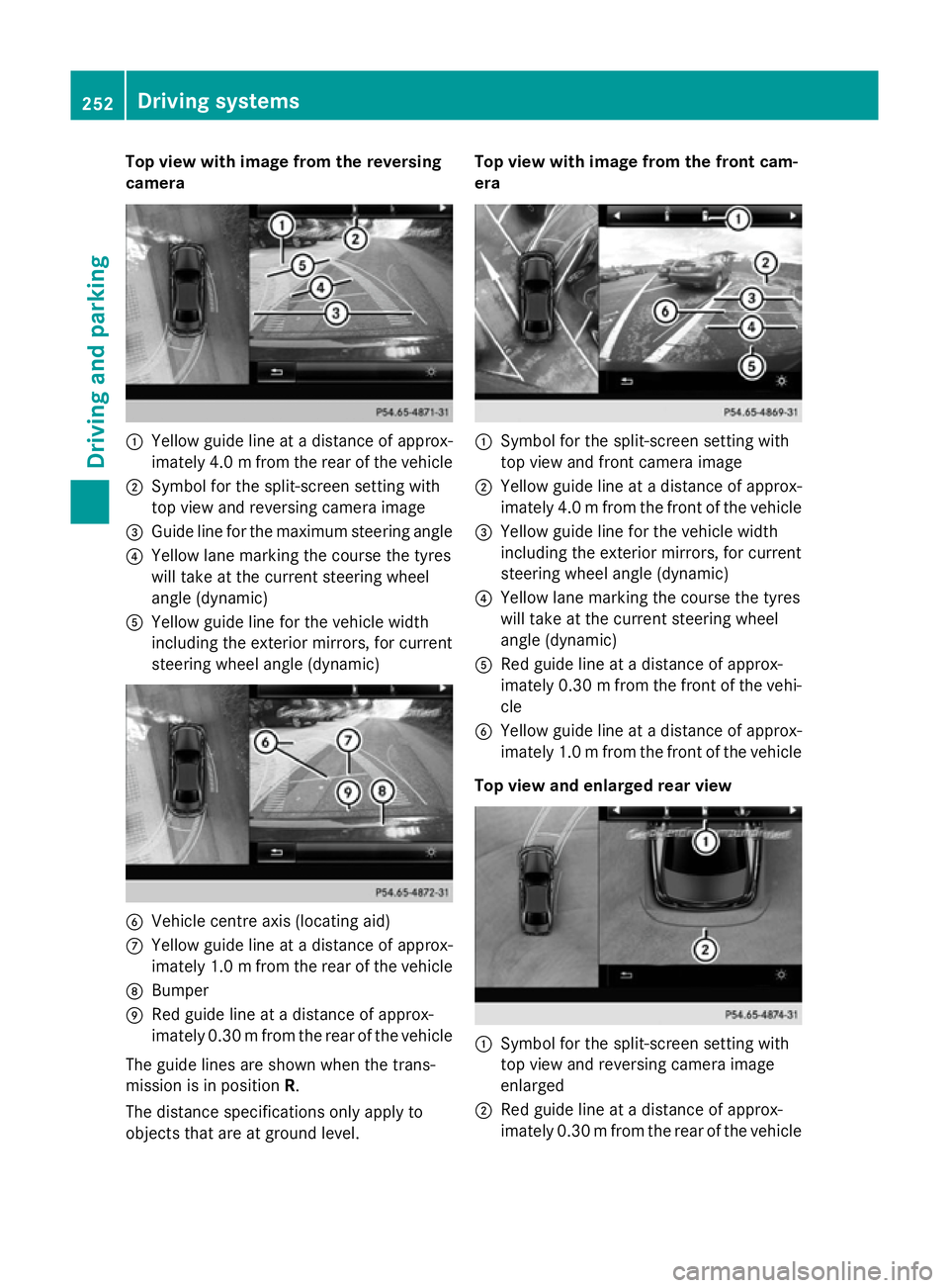
Top view with imag
efrom the reversing
camera :
Yellow guid elineatad istance of approx-
imatel y4.0mf rom the rear of the vehicle
; Symbol for the split-screen setting with
top view and reversing camera image
= Guide line for the maximu msteering angle
? Yellow lane marking the course the tyres
willt ake at the current steering wheel
angle (dynamic)
A Yellow guide line for the vehicl ewidth
including the exterior mirrors, for current
steering whee langle (dynamic) B
Vehicle centre axis (locating aid)
C Yellow guide line at adistance of approx-
imatel y1.0mf rom the rear of the vehicle
D Bumper
E Red guide line at adistance of approx-
imatel y0.30 mfrom the rear of the vehicle
The guide lines are show nwhen the trans-
mission is in position R.
The distance specifications only apply to
objects that are at ground level. Top vieww
ith image from the front cam-
era :
Symbol for the split-screen setting with
top view and front camera image
; Yellow guide line at adistance of approx-
imatel y4.0mf rom the front of the vehicle
= Yellow guide line for the vehicl ewidth
including the exterior mirrors, for current
steering whee langle (dynamic)
? Yellow lane marking the course the tyres
willt ake at the current steering wheel
angle (dynamic)
A Red guide line at adistance of approx-
imatel y0.30 mfrom the front of the vehi-
cle
B Yellow guide line at adistance of approx-
imatel y1.0mf rom the front of the vehicle
Top viewa nd enlarged rear view :
Symbol for the split-screen setting with
top view and reversing camera image
enlarged
; Red guide line at adistance of approx-
imatel y0.30 mfrom the rear of the vehicle 252
Driving systemsDriving and parking
Page 256 of 497
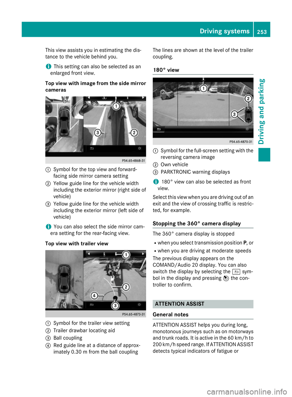
This view assists you in estimatin
gthe dis-
tancetot he vehicle behind you.
i This setting can also be selected as an
enlarged frontv iew.
Top view with image from the side mirror cameras :
Symbol for the top view and forward-
facing side mirror camera setting
; Yellow guide line for the vehicle width
including the exterior mirror (right side of vehicle)
= Yellow guide line for the vehicle width
including the exterior mirror (left side of
vehicle)
i You can also select the side mirror cam-
era setting for the rear-facing view.
Top view with trailer view :
Symbol for the trailer view setting
; Trailer drawbar locating aid
= Ball coupling
? Red guide line at adistanc eofapprox-
imately 0.30m from the ball coupling The lines are shown at the level of the trailer
coupling.
180° view :
Symbol for the full-screen setting with the
reversin gcamera image
; Own vehicle
= PARKTRONIC warning displays
i 180° view can also be selected as front
view.
Select this view when you are driving out of an
exit and the view of crossin gtraffic is restric-
ted, for example.
Stopping the 360° camera display The 360° camera display is stopped
R when you select transmission position P,or
R when you are driving at moderate speeds
The previous display appears on the
COMAND/Audio 20 display .You can also
switch the display by selectin gthe & sym-
bol in the display and pressing 7the con-
troller to confirm. ATTENTION ASSIST
General notes ATTENTION ASSIST helps you during long,
monotonous journeys such as on motorways
and trunk roads. It is active in the 60 km/hto
200 km/h spee drange .IfATTENTION ASSIST
detects typical indicators of fatigue or Driving systems
253Driving and parking Z
Page 366 of 497
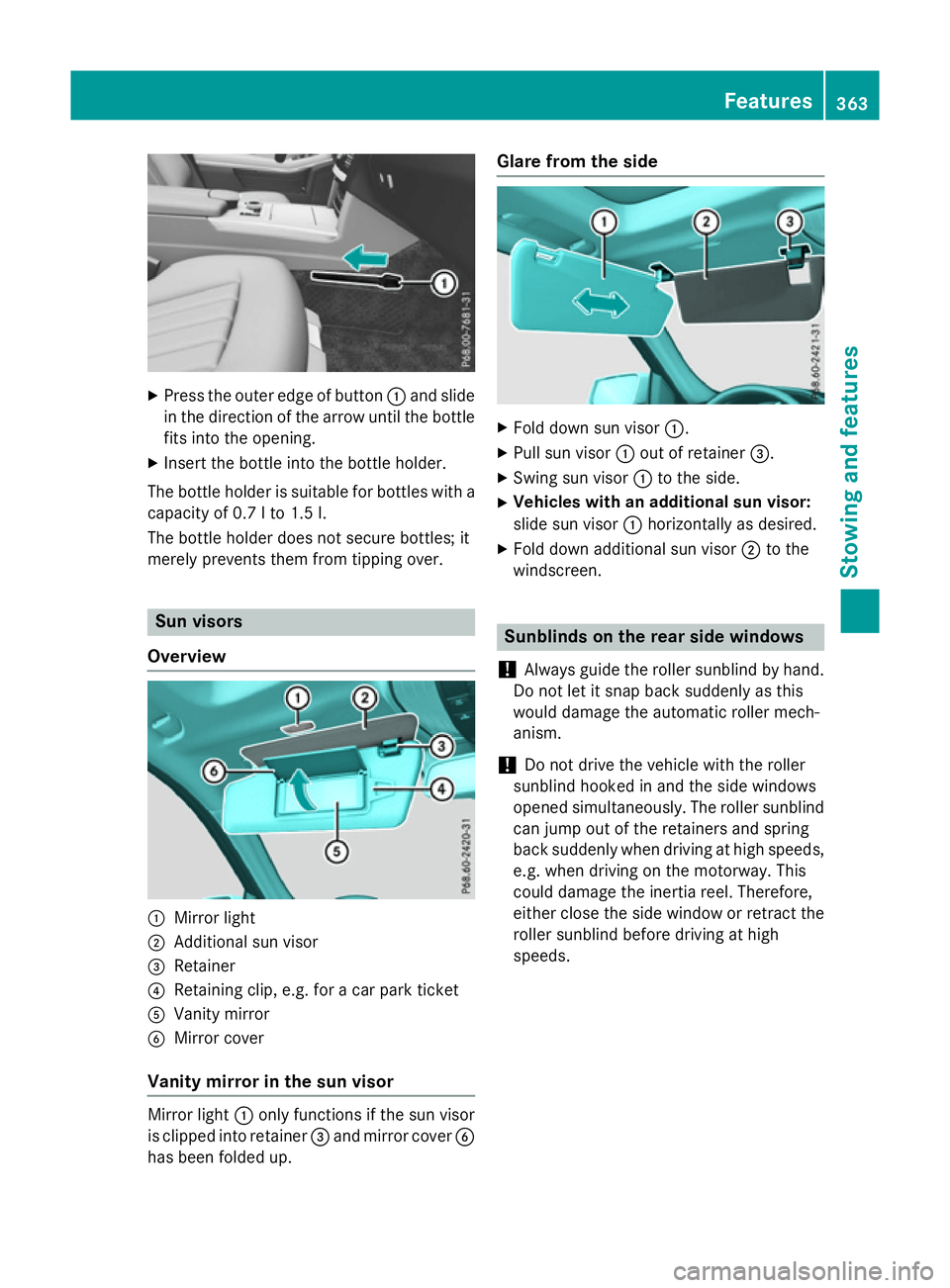
X
Press the outer edge of button :and slide
in the direction of the arrow until the bottle
fits into the opening.
X Inser tthe bottle into the bottle holder.
The bottle holder is suitable for bottles with a
capacity of 0.7 lto1 .5l.
The bottle holder does not secure bottles; it
merely prevent sthem from tipping over. Sun visors
Overview :
Mirror light
; Additional sun visor
= Retainer
? Retaining clip, e.g. for acar park ticket
A Vanity mirror
B Mirror cover
Vanit ymirror in the sun visor Mirror light
:only functions if the sun visor
is clipped into retainer =and mirror cover B
has been folded up. Glare from the side
X
Fold down sun visor :.
X Pull sun visor :out of retainer =.
X Swing sun visor :to the side.
X Vehicles with an additional sun visor:
slide sun visor :horizontally as desired.
X Fold down additional sun visor ;to the
windscreen. Sunblinds on the rear side windows
! Always guide the roller sunblind by hand.
Do not let it snap back suddenly as this
would damage the automatic roller mech-
anism.
! Do not drive the vehicle with the roller
sunblind hooked in and the side windows
opened simultaneously. The roller sunblind can jump out of the retainers and spring
back suddenly when driving at high speeds,
e.g. when driving on the motorway. This
could damage the inertia reel. Therefore,
either close the side window or retrac tthe
roller sunblind before driving at high
speeds. Features
363Stowing and features Z
Page 371 of 497
More information on suitable mobile phones,
mobile phone brackets and on connecting
Bluetooth ®
-capable mobile phones to
COMAND Online/Audio 20 can be obtained:
R at your Mercedes-Ben zService Centre
R on the Internet at http://www.mercedes-
benz.com/connect
The functions and services available when
you use the phone depend on your mobile
phone model and service provider.
Using amobile phone To connect
amobile phone to the exterior
aerial and charge it, insert it into the mobile
phone bracket.
X Open the telephone compartment
(Y page 344).
X Place the mobile phone bracket into the
pre-installed fitting; see the separate instal-
lation instructions for the mobile phone fit-
ting.
X Insert the mobile phone into the mobile
phone bracket; see the separate installa-
tion instructions for the mobile phone fit-
ting.
i The mobile phone can also be operated
without being in the bracket. However, the charging function and aerial function are
not available.
In order to use Bluetooth ®
(SAP profile) on
your telephone module, you must first insert
the telephone module into the pre-installed
fitting. This connects it to the exterior aerial.
If you wish to charge the mobile phone, then
you must connect it to aUSB port.
Further information on the telephone module
with Bluetooth ®
(SAP profile) can be found in
the Digital Owner's Manual.
Operating the mobile phone You can operate the telephone using the
6 and~ buttons on the multifunction
steering wheel. You can operate other mobile phone functions via the on-board computer
(Y page 284).
When you remove the key from the ignition
lock, the mobile phone is disconnected from
the hands-free system. Active calls will first
be transferred to the mobile phone directly.
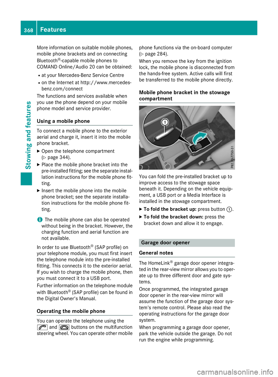
Mobile phone bracket in the stowage
compartment You can fold the pre-installed bracket up to
improve access to the stowage space
beneath it. Depending on the vehicle equip-
ment,aU
SB port or aMedia Interface is
installed in the stowage compartment.
X To fold the bracket up: press button:.
X To fold the bracket down: press the
bracket down and allow it to engage. Garage door opener
General notes The HomeLink
®
garage door opener integra-
ted in the rear-view mirror allowsy ou to oper-
ate up to three different door and gate sys-
tems.
Once programmed, the integrated garage
door opener in the rear-view mirror will
assume the function of the garage door sys-
tem's remote control. Please also read the
operating instructions for the garage door
system.
When programming agarage door opener,
park the vehicle outside the garage. Do not
run the engine while programming. 368
FeaturesStowing and features