2015 MERCEDES-BENZ CLA SHOOTING BRAKE ignition
[x] Cancel search: ignitionPage 223 of 421
Problems with PARKTRONIC
Problem
Possible causes/consequences and
M
MSolutions Only the red segments
in the PARKTRONIC
warning displays are lit.
You also hear a warning
tone for approximately
two seconds.
PARKTRONIC is then
deactivated and the
indicator lamp on the
PARKTRONIC button
lights up. PARKTRONIC has malfunctioned and has been deactivated.
X If problems persist, have PARKTRONIC checked at a qualified
specialist workshop. Only the red segments
in the PARKTRONIC
warning displays are lit.
PARKTRONIC is then
deactivated. The PARKTRONIC sensors are dirty or there is interference.
X Clean the PARKTRONIC sensors (Y page 344).
X Switch the ignition back on. The problem may be caused by an external source of radio or
ultrasound waves.
X See if PARKTRONIC functions in a different location. Active Parking Assist
General notes Active Parking Assist is an electronic parking
aid with ultrasound. It measures the road on
both sides of the vehicle. A parking symbol
indicates a suitable parking space. Active
steering intervention and brake application
can assist you during parking and when exit-
ing a parking space. You may also use
PARKTRONIC (Y page 216).
i The active braking application is only
available on vehicles with automatic trans-
mission.
Important safety notes Active Parking Assist is only an aid. It is not a
substitute for your attention to the immediate
surroundings. The responsibility for safe
manoeuvring and parking remains with you. Make sure that no persons, animals or
objects are in the manoeuvring range.
When PARKTRONIC is deactivated, Active
Parking Assist is also unavailable. G
WARNING
While parking or pulling out of a parking
space, the vehicle swings out and can drive
onto areas of the oncoming lane. This could
cause you to collide with other road users.
There is a risk of an accident.
Pay attention to other road users. Stop the
vehicle if necessary or cancel the Active Park- ing Assist parking procedure.
! If unavoidable, you should drive over
obstacles such as kerbs slowly and not at a
sharp angle. Otherwise, you may damage
the wheels or tyres. 220
Driving systemsDriving and parking
Page 229 of 421
Under the following circumstances, the
reversing camera will not function, or will
function in a limited manner:
R if the tailgate is open
R in heavy rain, snow or fog
R at night or in very dark places
R if the camera is exposed to very bright light
R if the area is lit by fluorescent bulbs or LED
lighting (the display may flicker)
R if there is a sudden change in temperature,
e.g. when driving into a heated garage in
winter
R if the camera lens is dirty or obstructed.
Observe the notes on cleaning
(Y page 344)
R if the rear of your vehicle is damaged. In this
case, have the camera position and setting
checked at a qualified specialist workshop.
The field of vision and other functions of the
reversing camera may be restricted due to
additional accessories on the rear of the vehi-
cle (e.g. licence plate holder, bicycle rack).
Activating/deactivating the reversing
camera X
To activate: make sure that the key is in
position 2in the ignition lock.
X Make sure that the Activation by R
Activation by R
gear
gear function is selected in Audio 20/ COMAND Online; see the Digital Owner's
Manual.
X Engage reverse gear.
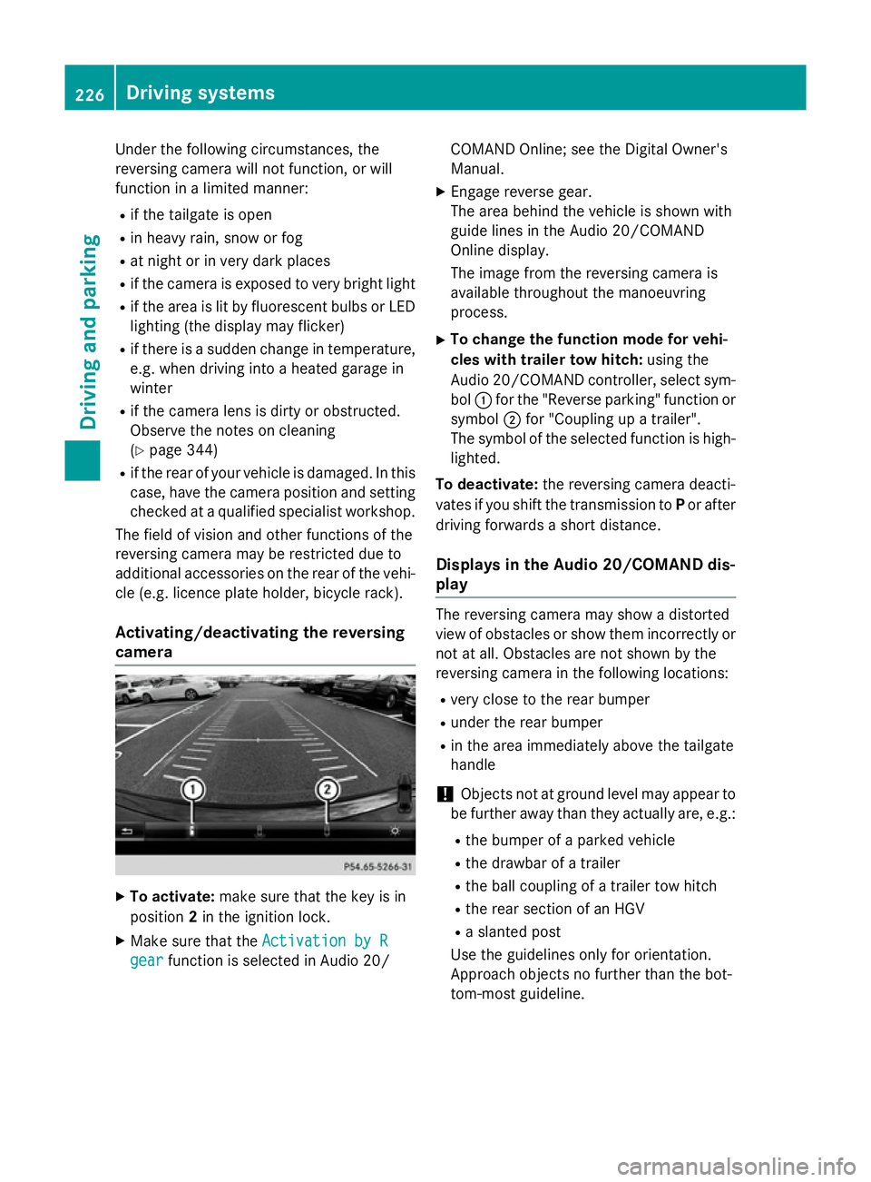
The area behind the vehicle is shown with
guide lines in the Audio 20/COMAND
Online display.
The image from the reversing camera is
available throughout the manoeuvring
process.
X To change the function mode for vehi-
cles with trailer tow hitch: using the
Audio 20/COMAND controller, select sym- bol :for the "Reverse parking" function or
symbol ;for "Coupling up a trailer".
The symbol of the selected function is high- lighted.
To deactivate: the reversing camera deacti-
vates if you shift the transmission to Por after
driving forwards a short distance.
Displays in the Audio 20/COMAND dis-
play The reversing camera may show a distorted
view of obstacles or show them incorrectly or
not at all. Obstacles are not shown by the
reversing camera in the following locations:
R very close to the rear bumper
R under the rear bumper
R in the area immediately above the tailgate
handle
! Objects not at ground level may appear to
be further away than they actually are, e.g.:
R the bumper of a parked vehicle
R the drawbar of a trailer
R the ball coupling of a trailer tow hitch
R the rear section of an HGV
R a slanted post
Use the guidelines only for orientation.
Approach objects no further than the bot-
tom-most guideline. 226
Driving systemsDriving and parking
Page 239 of 421
Activating Blind Spot Assist
X Make sure that Blind Spot Assist is activa-
ted in the on-board computer
(Y page 257).
X Turn the key to position 2in the ignition
lock.
Warning lamps :in the exterior mirrors
light up red for approximately 1.5 seconds
and then turn yellow.
Towing a trailer
If you couple up a trailer, make sure that you have correctly established the electrical con-
nection. This can be accomplished by check- ing the trailer lighting. Blind Spot Assist is
then deactivated. The indicator lamps in the
exterior mirrors light up yellow and the
Blind
Blind Spot SpotAssist
Assist not
notavailable
available when
when
towing a trailer See Owner's Manual
towing a trailer See Owner's Manual
message appears in the multifunction dis-
play.
i You can deactivate the indicator lamps in
the exterior mirrors.
To do so, you will need to deactivate Blind
Spot Assist if:
R the key is in position 2in the ignition lock
R the engine is not running
R the electrical connection to the trailer
has been established
Lane Keeping Assist General notes
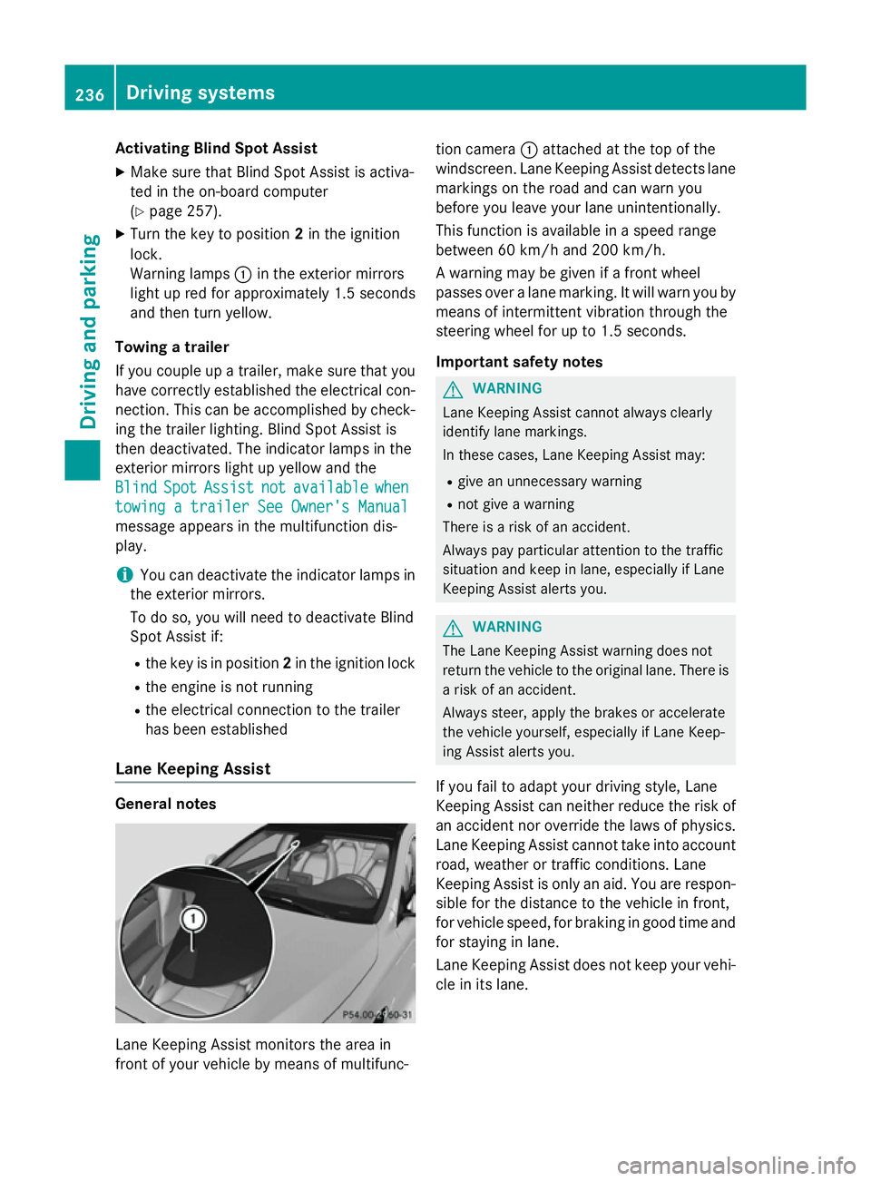
Lane Keeping Assist monitors the area in
front of your vehicle by means of multifunc- tion camera
:attached at the top of the
windscreen. Lane Keeping Assist detects lane markings on the road and can warn you
before you leave your lane unintentionally.
This function is available in a speed range
between 60 km/h and 200 km/h.
A warning may be given if a front wheel
passes over a lane marking. It will warn you by
means of intermittent vibration through the
steering wheel for up to 1.5 seconds.
Important safety notes G
WARNING
Lane Keeping Assist cannot always clearly
identify lane markings.
In these cases, Lane Keeping Assist may:
R give an unnecessary warning
R not give a warning
There is a risk of an accident.
Always pay particular attention to the traffic
situation and keep in lane, especially if Lane
Keeping Assist alerts you. G
WARNING
The Lane Keeping Assist warning does not
return the vehicle to the original lane. There is a risk of an accident.
Always steer, apply the brakes or accelerate
the vehicle yourself, especially if Lane Keep-
ing Assist alerts you.
If you fail to adapt your driving style, Lane
Keeping Assist can neither reduce the risk of
an accident nor override the laws of physics. Lane Keeping Assist cannot take into account
road, weather or traffic conditions. Lane
Keeping Assist is only an aid. You are respon- sible for the distance to the vehicle in front,
for vehicle speed, for braking in good time and
for staying in lane.
Lane Keeping Assist does not keep your vehi- cle in its lane. 236
Driving systemsDriving and pa
rking
Page 245 of 421
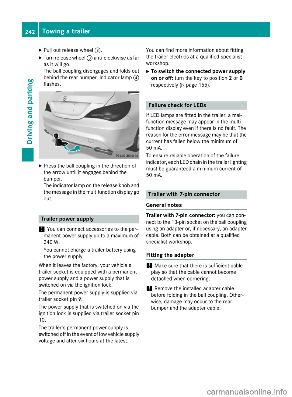
X
Pull out release wheel =.
X Turn release wheel =anti-clockwise as far
as it will go.
The ball coupling disengages and folds out
behind the rear bumper. Indicator lamp ?
flashes. X
Press the ball coupling in the direction of
the arrow until it engages behind the
bumper.
The indicator lamp on the release knob and
the message in the multifunction display go
out. Trailer power supply
! You can connect accessories to the per-
manent power supply up to a maximum of
240 W.
You cannot charge a trailer battery using
the power supply.
When it leaves the factory, your vehicle's
trailer socket is equipped with a permanent
power supply and a power supply that is
switched on via the ignition lock.
The permanent power supply is supplied via
trailer socket pin 9.
The power supply that is switched on via the
ignition lock is supplied via trailer socket pin
10.
The trailer's permanent power supply is
switched off in the event of low vehicle supply
voltage and after six hours at the latest. You can find more information about fitting
the trailer electrics at a qualified specialist
workshop.
X To switch the connected power supply
on or off: turn the key to position 2or 0
respectively (Y page 165). Failure check for LEDs
If LED lamps are fitted in the trailer, a mal-
function message may appear in the multi-
function display even if there is no fault. The
reason for the error message may be that the
current has fallen below the minimum of
50 mA.
To ensure reliable operation of the failure
indicator, each LED chain in the trailer lighting
must be guaranteed a minimum current of
50 mA. Trailer with 7-pin connector
General notes Trailer with 7-pin connector:
you can con-
nect to the 13-pin socket on the ball coupling
using an adapter or, if necessary, an adapter
cable. Both can be obtained at a qualified
specialist workshop.
Fitting the adapter !
Make sure that there is sufficient cable
play so that the cable cannot become
detached when cornering.
! Remove the installed adapter cable
before folding in the ball coupling. Other-
wise, damage may occur to the rear
bumper and the adapter cable. 242
Towing a trailerDriving and parking
Page 250 of 421

The segments between the speed of the
vehicle in front and the stored speed light
up. Rev counter
! Do not drive in the overrevving range.
Doing so will damage the engine.
The red band in the rev counter indicates the
engine's overrevving range.
The engine is limited within a range to protect the engine when the red band is reached. Outside temperature display
You should pay special attention to road con-
ditions when temperatures are around freez-
ing point.
Bear in mind that the outside temperature
display indicates the measured air tempera-
ture and not the road surface temperature.
The outside temperature display is in the mul- tifunction display (Y page 249).
There is a short delay before a change in out- side temperature appears in the multifunc-
tion display. Coolant temperature gauge
G
WARNING
If you open the bonnet while the engine is
overheating or while there is a fire in the
engine compartment, you could come into
contact with hot gases or other leaking ser-
vice products. There is a danger of injury.
Allow an overheating engine to cool down
before opening the bonnet. If there is a fire in the engine compartment, leave the bonnet
closed and notify the fire brigade.
The coolant temperature gauge is in the
instrument cluster on the right-hand side
(Y page 32). Under normal operating conditions and with
the specified coolant level, the coolant tem-
perature may rise to 120 †.
At high outside temperatures and when driv-
ing uphill, the coolant temperature may rise
to the end of the scale. Operating the on-board computer
Overview :
Multifunction display
; Right control panel
= Left control panel
X To activate the on-board computer: turn
the key to position 1in the ignition lock.
You can control the multifunction display and
the settings in the on-board computer using
the buttons on the multifunction steering
wheel. Displays and operation
247On-board computer and displays Z
Page 253 of 421
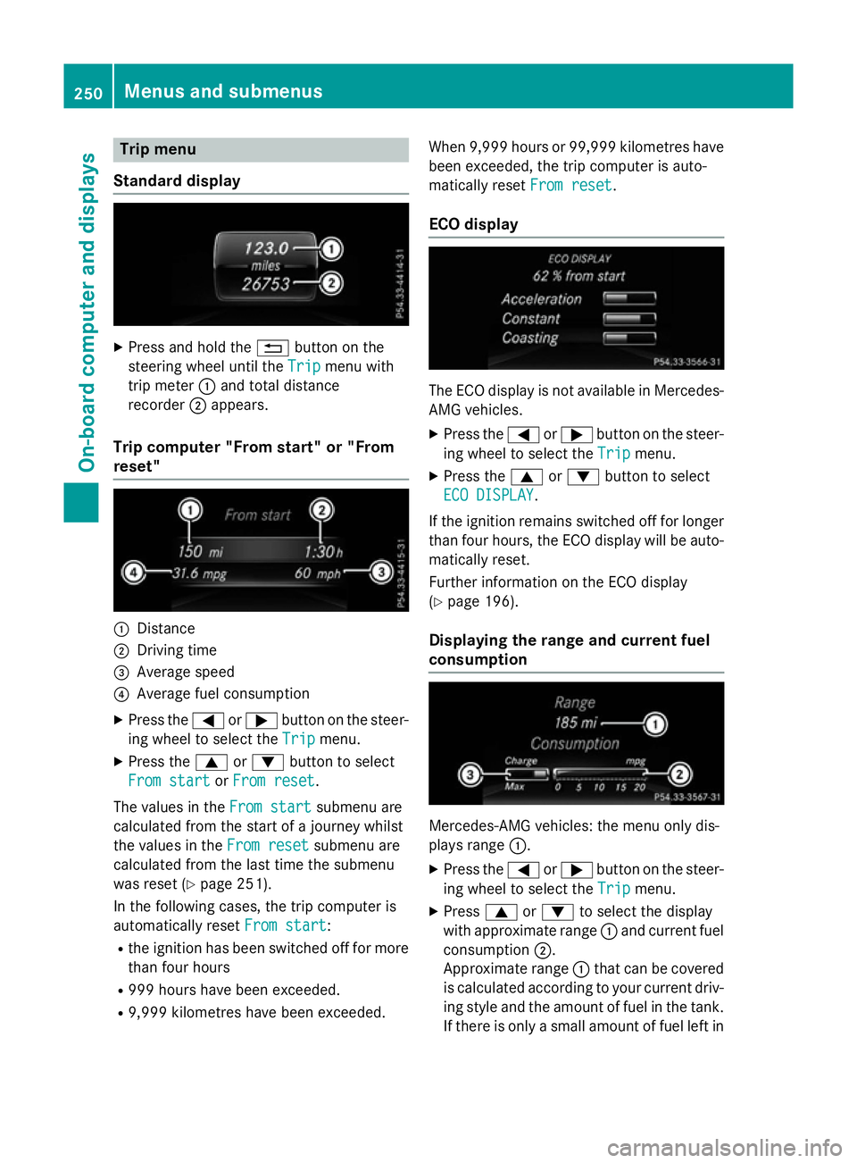
Trip menu
Standard display X
Press and hold the %button on the
steering wheel until the Trip
Tripmenu with
trip meter :and total distance
recorder ;appears.
Trip computer "From start" or "From
reset" :
Distance
; Driving time
= Average speed
? Average fuel consumption
X Press the =or; button on the steer-
ing wheel to select the Trip Tripmenu.
X Press the 9or: button to select
From start
From start orFrom reset
From reset.
The values in the From start
From startsubmenu are
calculated from the start of a journey whilst
the values in the From reset From resetsubmenu are
calculated from the last time the submenu
was reset (Y page 251).
In the following cases, the trip computer is
automatically reset From start
From start:
R the ignition has been switched off for more
than four hours
R 999 hours have been exceeded.
R 9,999 kilometres have been exceeded. When 9,999 hours or 99,999 kilometres have
been exceeded, the trip computer is auto-
matically reset From reset
From reset.
ECO display The ECO display is not available in Mercedes-
AMG vehicles.
X Press the =or; button on the steer-
ing wheel to select the Trip Tripmenu.
X Press the 9or: button to select
ECO DISPLAY
ECO DISPLAY.
If the ignition remains switched off for longer
than four hours, the ECO display will be auto- matically reset.
Further information on the ECO display
(Y page 196).
Displaying the range and current fuel
consumption Mercedes-AMG vehicles: the menu only dis-
plays range
:.
X Press the =or; button on the steer-
ing wheel to select the Trip Tripmenu.
X Press 9or: to select the display
with approximate range :and current fuel
consumption ;.
Approximate range :that can be covered
is calculated according to your current driv-
ing style and the amount of fuel in the tank. If there is only a small amount of fuel left in 250
Menus and submenusOn-board computer and displays
Page 266 of 421
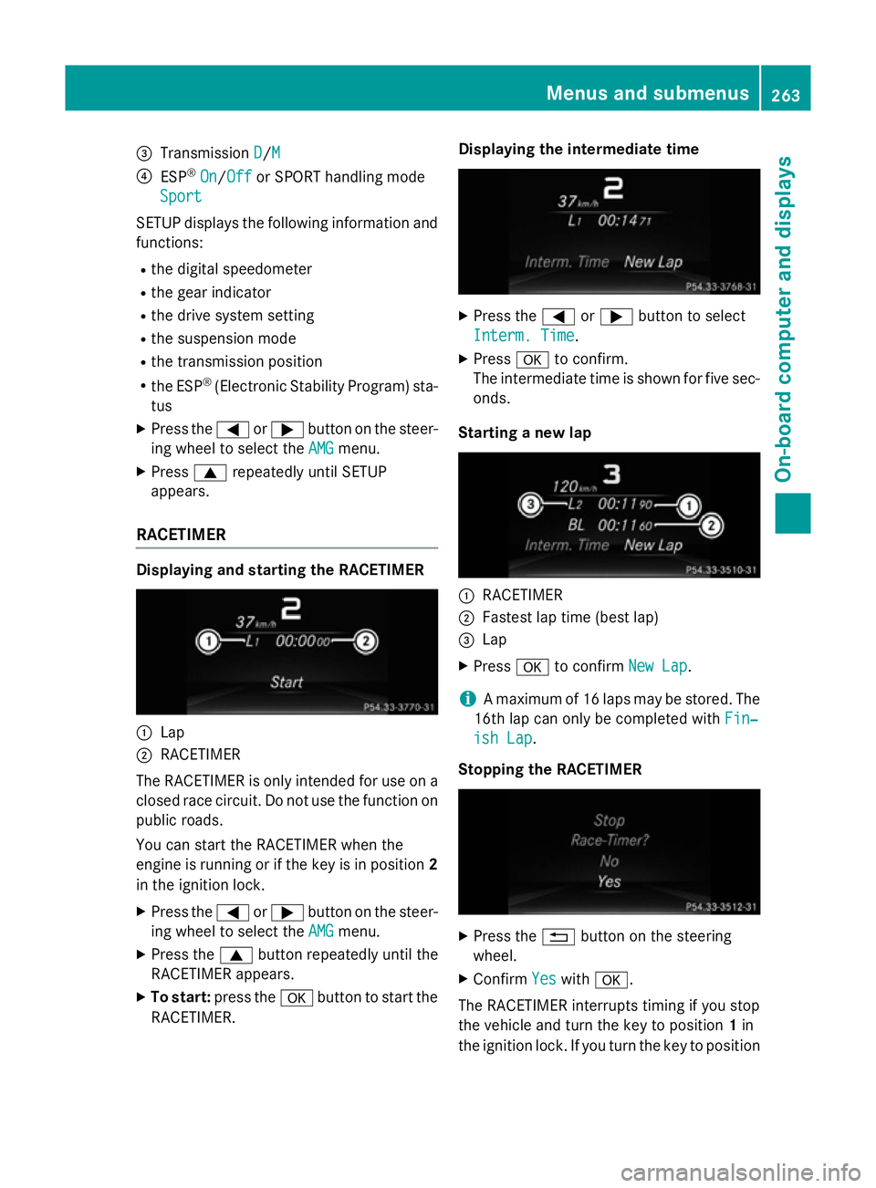
=
Transmission D
D/MM
? ESP ®
On
On/Off Off or SPORT handling mode
Sport
Sport
SETUP displays the following information and
functions:
R the digital speedometer
R the gear indicator
R the drive system setting
R the suspension mode
R the transmission position
R the ESP ®
(Electronic Stability Program) sta-
tus
X Press the =or; button on the steer-
ing wheel to select the AMG
AMGmenu.
X Press 9repeatedly until SETUP
appears.
RACETIMER Displaying and starting the RACETIMER
:
Lap
; RACETIMER
The RACETIMER is only intended for use on a closed race circuit. Do not use the function on
public roads.
You can start the RACETIMER when the
engine is running or if the key is in position 2
in the ignition lock.
X Press the =or; button on the steer-
ing wheel to select the AMG
AMG menu.
X Press the 9button repeatedly until the
RACETIMER appears.
X To start: press the abutton to start the
RACETIMER. Displaying the intermediate time
X
Press the =or; button to select
Interm. Time Interm. Time.
X Press ato confirm.
The intermediate time is shown for five sec-
onds.
Starting a new lap :
RACETIMER
; Fastest lap time (best lap)
= Lap
X Press ato confirm New Lap
New Lap.
i A maximum of 16 laps may be stored. The
16th lap can only be completed with Fin‐
Fin‐
ish Lap
ish Lap.
Stopping the RACETIMER X
Press the %button on the steering
wheel.
X Confirm Yes
Yeswith a.
The RACETIMER interrupts timing if you stop
the vehicle and turn the key to position 1in
the ignition lock. If you turn the key to position Menus and submenus
263On-board computer and displays Z
Page 268 of 421
Display messages
Introduction
General notes Display messages appear in the multifunction display.
Display messages with graphic symbols are simplified in the Owner's Manual and may differ
from the symbols in the multifunction display.
Please respond in accordance with the display messages and follow the additional notes in this Owner's Manual.
Certain display messages are accompanied by an audible warning tone or a continuous tone.
When the ignition is switched off, all display messages are deleted apart from some high-
priority display messages. Once the causes of the high-priority display messages have been
rectified, these display messages are deleted as well.
When you stop and park the vehicle, please observe the notes on:
R HOLD function (Y page 211)
R Parking (Y page 192)
Hiding display messages X
Press the aor% button on the steering wheel.
The multifunction display hides the display message.
The multifunction display shows high-priority display messages in red. Some high-priority dis- play messages cannot be hidden.
The multifunction display shows these messages continuously until the causes for the mes-
sages have been remedied.
Message memory The on-board computer saves certain display messages in the
message memory. You can call
up the display messages:
X Press the =or; button on the steering wheel to select the Service Servicemenu.
If there are display messages, the multifunction display shows 2 messages
2 messages, for example.
X Press the 9or: button to select the entry, e.g. 2 messages
2 messages.
X Press ato confirm.
X Press the 9or: button to scroll through the display messages. Display
messages
265On-board computer and displays Z