2015 MERCEDES-BENZ B-Class ELECTRIC transmission
[x] Cancel search: transmissionPage 265 of 338
gramming of additional remote controls",
before carrying out the following steps.
Your vehicle must be within reach of the
garage door or gate opener drive. Make sure
that neither your vehicle nor any persons/
objects are present within the sweep of the
door or gate.
X Turn the SmartKey to position 2in the igni-
tion lock (Y page 131).
X Get out of the vehicle.
X Press the programming button on the door
drive unit.
Usually, you now have 30 seconds to ini-
tiate the next step.
X Get into the vehicle.
X Press previously programmed button ;,
= or? on the integrated garage door
opener until the door closes.
The rolling code synchronization is then
complete.
Notes on programming the remote con-
trol
Canadian radio frequency laws require a
"break" (or interruption) of the transmission
signals after broadcasting for a few seconds. Therefore, these signals may not last long
enough for the integrated garage door
opener. The signal is not recognized during
programming. Comparable with Canadian
law, some U.S. garage door openers also fea-
ture a "break".
Proceed as follows:
R if you live in Canada
R if you have difficulties programming the
garage door opener (regardless of where
you live) when using the programming
steps
X Press and hold one of buttons ;to? on
the integrated garage door opener.
After a short time, indicator lamp :lights
up yellow.
X Release the button.
Indicator lamp :flashes yellow. X
Press button Bof garage door remote
control Afor two seconds, then release it
for two seconds.
X Press button Bagain for two seconds.
X Repeat this sequence on button Bof
remote control Auntil indicator lamp :
lights up green.
When indicator lamp :lights up green:
programming is finished.
When indicator lamp :flashes green: pro-
gramming was successful. The next step is to synchronize the rolling code.
X Release button Bof remote control Aof
the garage door drive.
If indicator lamp :lights up red: repeat the
programming process for the correspond-
ing button on the rear-view mirror. When
doing so, vary the distance between remote
control Aand the rear-view mirror.
The required distance between remote
control Aand the integrated garage door
opener depends on the garage door drive
system. Several attempts might be neces-
sary. You should test every position for at
least 25 seconds before trying another
position.
Problems when programming
If you are experiencing problems programing
the integrated garage door opener on the
rear-view mirror, take note of the following
instructions:
R Check the transmitter frequency used by
garage door drive remote control Aand
whether it is supported. The transmitter
frequency can usually be found on the back
of the garage door drive remote control.
The integrated garage door opener is com-
patible with devices that have units which
operate in the frequency range of 280 to
433 MHz.
R Replace the batteries in garage door
remote control A. This increases the like-
lihood that garage door remote control A
will transmit a strong and precise signal to the integrated garage door opener. Features
263Stowage and features Z
Page 266 of 338
R
When programming, hold remote control
A at varying distances and angles from the
button which you are programming. Try var- ious angles at a distance between 2and
12 inches (5to 30 cm) or at the same angle
but at varying distances.
R If another remote control is available for the
same garage door drive, repeat the same
programming steps with this remote con-
trol. Before performing these steps, make
sure that new batteries have been installed in garage door drive remote control A.
R Note that some remote controls only trans-
mit for a limited amount of time (the indi-
cator lamp on the remote control goes out). Press button Bon remote control Aagain
before transmission ends.
R Align the antenna cable of the garage door
opener unit. This can improve signal recep- tion/transmission.
Opening/closing the garage door After it has been programmed, the integrated
garage door opener performs the function of
the garage door system remote control.
Please also read the operating instructions
for the garage door system.
X Turn the SmartKey to position 2in the igni-
tion lock (Y page 131).
X Press button ;,=or? which you have
programmed to operate the garage door.
Garage door system with a fixed code: indi-
cator lamp :lights up green.
Garage door system with a rolling code:
indicator lamp :flashes green.
The transmitter will transmit a signal as
long as the button is pressed. The trans-
mission is halted after a maximum of ten
seconds and indicator lamp :lights up
yellow.
X Press button ;,=or? again if neces-
sary. Clearing the memory Make sure that you clear the memory of the
integrated garage door opener before selling
the vehicle.
X Turn the SmartKey to position 2in the igni-
tion lock (Y page 131).
X Press and hold buttons ;and ?.
The indicator lamp initially lights up yellow
and then green.
X Release buttons ;and ?.
The memory of the integrated garage door
opener in the rear-view mirror is cleared. Compass
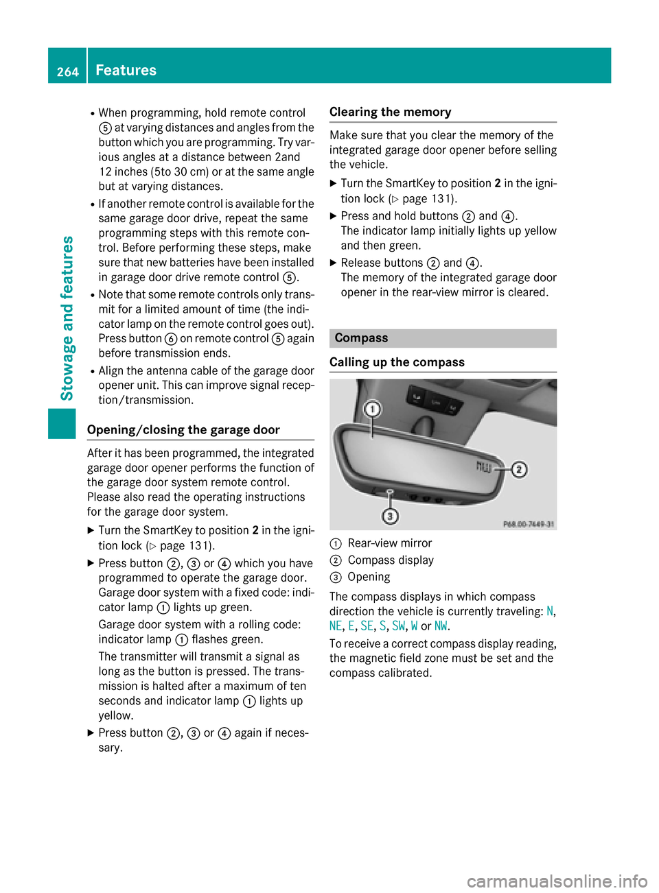
Calling up the compass :
Rear-view mirror
; Compass display
= Opening
The compass displays in which compass
direction the vehicle is currently traveling: N N,
NE
NE, E
E,SE
SE, S
S,SW
SW, W
Wor NW
NW.
To receive a correct compass display reading, the magnetic field zone must be set and the
compass calibrated. 264
FeaturesStowage and features
Page 267 of 338
Setting the compass
X
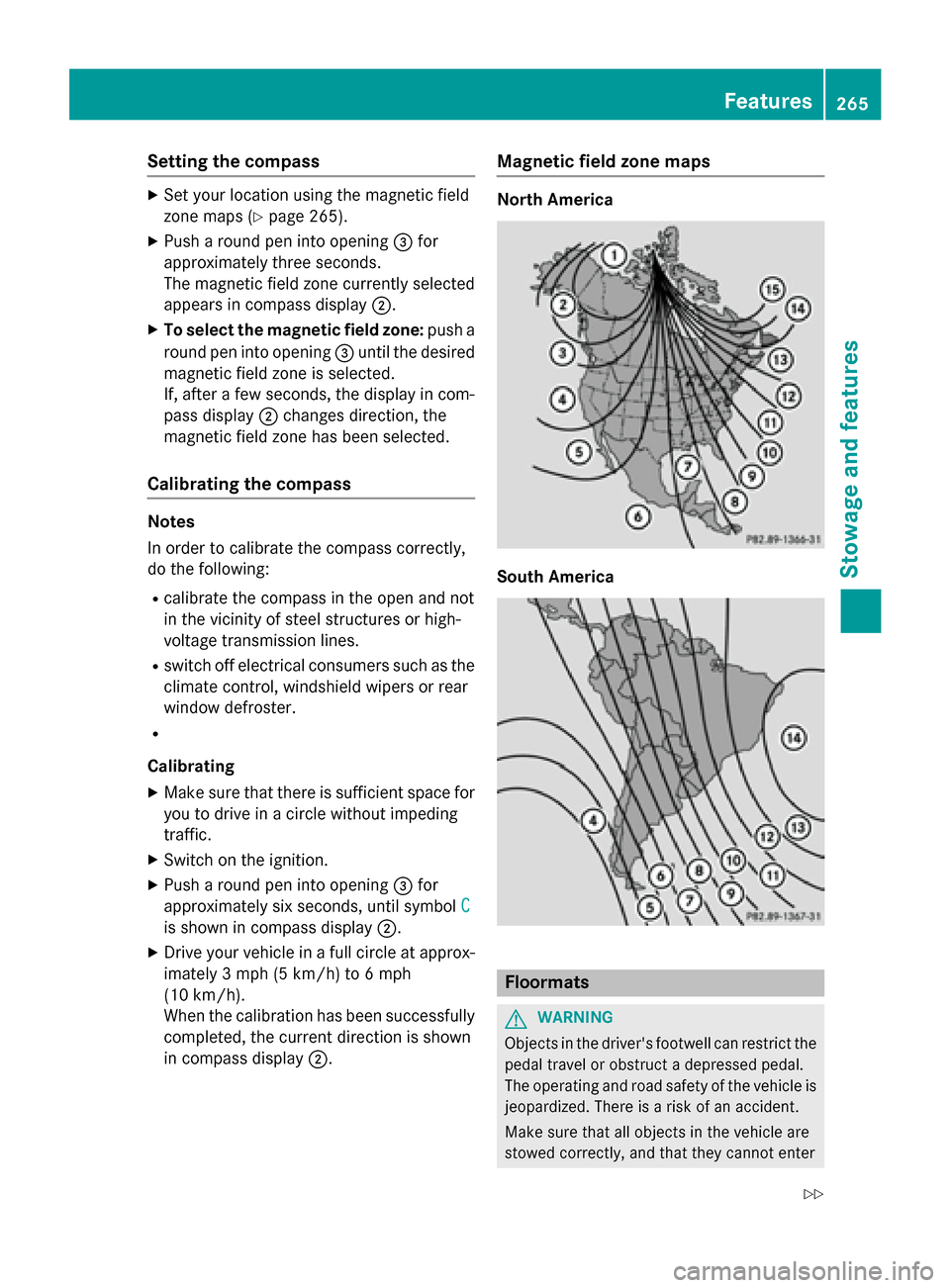
Set your location using the magnetic field
zone maps (Y page 265).
X Push a round pen into opening =for
approximately three seconds.
The magnetic field zone currently selected
appears in compass display ;.
X To select the magnetic field zone: push a
round pen into opening =until the desired
magnetic field zone is selected.
If, after a few seconds, the display in com-
pass display ;changes direction, the
magnetic field zone has been selected.
Calibrating the compass Notes
In order to calibrate the compass correctly,
do the following:
R calibrate the compass in the open and not
in the vicinity of steel structures or high-
voltage transmission lines.
R switch off electrical consumers such as the
climate control, windshield wipers or rear
window defroster.
R
Calibrating
X Make sure that there is sufficient space for
you to drive in a circle without impeding
traffic.
X Switch on the ignition.
X Push a round pen into opening =for
approximately six seconds, until symbol C
C
is shown in compass display ;.
X Drive your vehicle in a full circle at approx-
imately 3 mph (5 km/h) to 6 mph
(10 km/h).
When the calibration has been successfully completed, the current direction is shown
in compass display ;. Magnetic field zone maps North America
South America
Floormats
G
WARNING
Objects in the driver's footwell can restrict the pedal travel or obstruct a depressed pedal.
The operating and road safety of the vehicle is
jeopardized. There is a risk of an accident.
Make sure that all objects in the vehicle are
stowed correctly, and that they cannot enter Features
265Stowage and features
Z
Page 293 of 338
The drive system cannot be started if the 12 V battery is discharged. This is not dependent on
whether the high-voltage battery is charged or not. The vehicle cannot be jump-started if the
high-voltage battery is discharged. The high-voltage battery must be charged first.
The drive system can be started using another vehicle. R Only use batteries with an equal nominal voltage (12 volts).
R Make sure that the battery of the donor vehicle does not have a significantly lower capacity
than the discharged battery.
R Use jumper cables with a sufficient cross-section and insulated terminal clamps from a
qualified specialist workshop, e.g. an authorized Mercedes-Benz Center.
R Make sure that the two vehicles do not touch.
R Route the jumper cables so that they cannot be caught by rotating components in the engine
compartment.
R Do not disconnect the discharged battery from the vehicle's electrical system. X
Switch off the engine of both vehicles.
X Shift the transmission to position P.
X Switch off all electrical consumers.
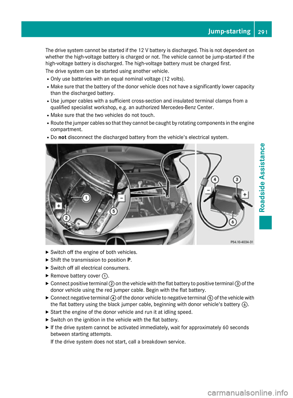
X Remove battery cover :.
X Connect positive terminal ;on the vehicle with the flat battery to positive terminal =of the
donor vehicle using the red jumper cable. Begin with the flat battery.
X Connect negative terminal ?of the donor vehicle to negative terminal Aof the vehicle with
the flat battery using the black jumper cable, beginning with donor vehicle's battery B.
X Start the engine of the donor vehicle and run it at idling speed.
X Switch on the ignition in the vehicle with the flat battery.
X If the drive system cannot be activated immediately, wait for approximately 60 seconds
between starting attempts.
If the drive system does not start, call a breakdown service. Jump-starting
291Roadside Assistance Z
Page 295 of 338
!
When towing, pull away slowly and
smoothly. If the tractive power is too high,
the vehicles could be damaged.
! The vehicle can be towed a maximum of
30 miles (50km). The towing speed of
30 mph (50km/h) must not be exceeded.
If the vehicle has to be towed more than
30 miles (50km), the front axle must be
raised or the entire vehicle raised and
transported.
! Do not tow with sling-type equipment.
This could damage the vehicle.
! To tow vehicles with KEYLESS-GO, use
the SmartKey instead of the Start/Stop
button. The transmission may otherwise
shift to position Pwhen you open the driv-
er's or front-passenger door, which could
damage the transmission.
Observe the legal requirements for the rele-
vant countries when towing away.
Make sure that no charging cable is plugged
in. The parking lock cannot be released if a
charging cable is plugged in.
It is better to have the vehicle transported
than to have it towed away.
If the vehicle can no longer be driven because
of an accident or breakdown, you have the
following options:
R transporting the vehicle
As a rule, you should have the vehicle trans-
ported.
R towing the vehicle with a tow rope or tow
bar
Only tow the vehicle in exceptional cases.
Observe the following notes.
The vehicle may not be towed and must
always be transported if:
R the multifunction display is not working
R one of more of the following warning lamps
is lit up:
- Drive system
- 12 V battery R
one or both of the following display mes-
sages have appeared:
- Stop Switch Engine Off
Stop Switch Engine Off
- Service Required Do Not Shift Service Required Do Not Shift
Gears Visit Dealer Gears Visit Dealer
R the brake pedal begins to pulsate as the
towing procedure commences.
R you have to tow the vehicle over a longer
distance than 30 miles (50 km)
When towing a vehicle, the transmission must be in position N.
The battery must be connected and charged.
Otherwise, you:
R cannot turn the SmartKey to position 2in
the ignition lock
R cannot release the electric parking brake
R cannot shift the transmission to position N
i The function of the electric parking brake
and the parking lock is dependent on the
on-board voltage.
If the on-board voltage is low or there is a
system malfunction, it is possible that:
R the electric parking brake may not be
applied in certain circumstances, or
R the transmission may not be shifted to P
i Switch off non-essential consumers, e.g.
the radio.
i Disarm the automatic locking feature
(Y page 198). You could otherwise be
locked out when pushing or towing the
vehicle. Towing
293Roadside Assistance Z
Page 296 of 338
Installing/removing the towing eye
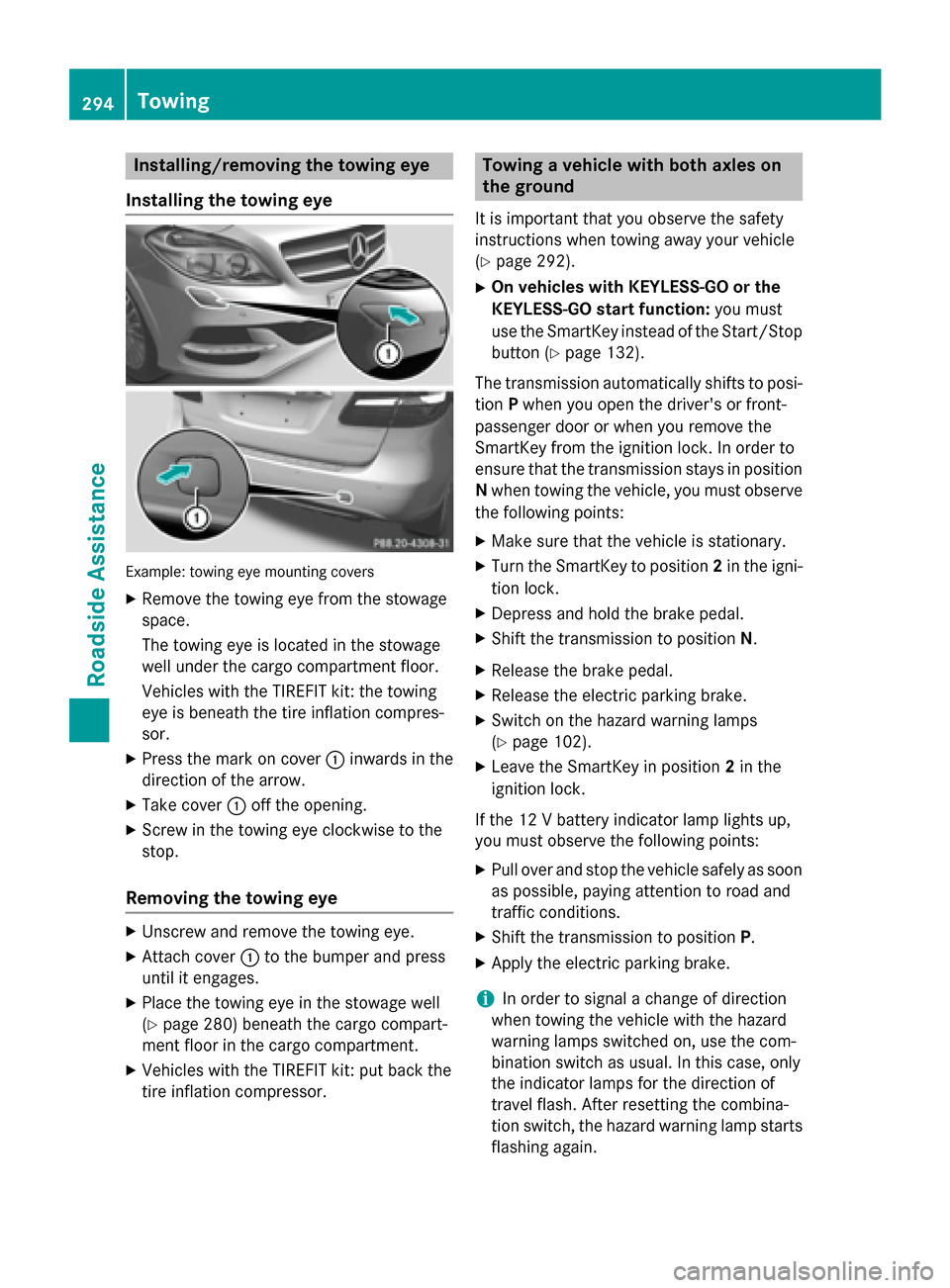
Installing the towing eye Example: towing eye mounting covers
X Remove the towing eye from the stowage
space.
The towing eye is located in the stowage
well under the cargo compartment floor.
Vehicles with the TIREFIT kit: the towing
eye is beneath the tire inflation compres-
sor.
X Press the mark on cover :inwards in the
direction of the arrow.
X Take cover :off the opening.
X Screw in the towing eye clockwise to the
stop.
Removing the towing eye X
Unscrew and remove the towing eye.
X Attach cover :to the bumper and press
until it engages.
X Place the towing eye in the stowage well
(Y page 280) beneath the cargo compart-
ment floor in the cargo compartment.
X Vehicles with the TIREFIT kit: put back the
tire inflation compressor. Towing a vehicle with both axles on
the ground
It is important that you observe the safety
instructions when towing away your vehicle
(Y page 292).
X On vehicles with KEYLESS-GO or the
KEYLESS-GO start function: you must
use the SmartKey instead of the Start/Stop
button (Y page 132).
The transmission automatically shifts to posi- tion Pwhen you open the driver's or front-
passenger door or when you remove the
SmartKey from the ignition lock. In order to
ensure that the transmission stays in position N when towing the vehicle, you must observe
the following points:
X Make sure that the vehicle is stationary.
X Turn the SmartKey to position 2in the igni-
tion lock.
X Depress and hold the brake pedal.
X Shift the transmission to position N.
X Release the brake pedal.
X Release the electric parking brake.
X Switch on the hazard warning lamps
(Y page 102).
X Leave the SmartKey in position 2in the
ignition lock.
If the 12 V battery indicator lamp lights up,
you must observe the following points:
X Pull over and stop the vehicle safely as soon
as possible, paying attention to road and
traffic conditions.
X Shift the transmission to position P.
X Apply the electric parking brake.
i In order to signal a change of direction
when towing the vehicle with the hazard
warning lamps switched on, use the com-
bination switch as usual. In this case, only
the indicator lamps for the direction of
travel flash. After resetting the combina-
tion switch, the hazard warning lamp starts
flashing again. 294
TowingRoadside Assistance
Page 297 of 338
Towing the vehicle with the front axle
raised
When towing your vehicle with the rear axle
raised, it is important that you observe the
safety instructions (Y page 292).
! The ignition must be switched off if the
vehicle is being towed with the front axle
raised. Otherwise, ESP ®
may intervene and
damage the brake system.
X On vehicles with KEYLESS-GO or the
KEYLESS-GO start function: you must
use the SmartKey instead of the Start/Stop button (Y page 132).
X Make sure that the vehicle is stationary.
X Turn the SmartKey to position 2in the igni-
tion lock.
X When the vehicle is stationary, depress the
brake pedal and keep it depressed.
X Shift the transmission to position P.
X Release the brake pedal.
X Release the electric parking brake.
X Switch off the automatic locking
(Y page 198).
X Switch on the hazard warning lamps
(Y page 102).
X Turn the SmartKey in the ignition lock to
position 0and leave the SmartKey in the
ignition lock. Towing the vehicle with the rear axle
raised
When towing your vehicle with the rear axle
raised, it is important that you observe the
safety instructions (Y page 292).
! The ignition must be switched off if you
are towing the vehicle with the rear axle
raised. Intervention by ESP ®
could other-
wise damage the brake system. The transmission automatically shifts to posi-
tion Pwhen you open the driver's or front-
passenger door or when you remove the
SmartKey from the ignition lock. In order to
ensure that the transmission stays in position N when towing the vehicle, you must observe
the following points:
X On vehicles with KEYLESS-GO or the
KEYLESS-GO start function: you must
use the SmartKey instead of the Start/Stop
button (Y page 132).
X Make sure that the vehicle is stationary.
X Turn the SmartKey to position 2in the igni-
tion lock.
X Depress and hold the brake pedal.
X Shift the transmission to position N.
X Release the brake pedal.
X Apply the electric parking brake.
X Switch off the automatic locking
(Y page 198).
X Bring the front wheels into the straight-
ahead position.
X Switch on the hazard warning lamps
(Y page 102).
X Turn the SmartKey in the ignition lock to
position 0and leave the SmartKey in the
ignition lock. Transporting the vehicle
! You may only secure the vehicle by the
wheels, not by parts of the vehicle such as
axle or steering components. Otherwise,
the vehicle could be damaged.
X Turn the SmartKey to position 2in the igni-
tion lock (Y page 131).
X Shift the transmission to position N.
As soon as the vehicle has been loaded:
X Prevent the vehicle from rolling away by
applying the electric parking brake.
X Shift the transmission to position P. Towing
295Roadside Assistance Z
Page 323 of 338

Occupant distribution
The distribution of occupants in a vehicle at
their designated seating positions.
Total load limit
Nominal load and luggage load plus 68 kg
(150 lbs) multiplied by the number of seats in the vehicle. Changing a wheel
Flat tire
The "Breakdown assistance" section
(Y page 280) contains information and notes
on how to deal with a flat tire. Information on driving with MOExtended tires in the event of
a flat tire can be found under "MOExtended
tires (tires with run-flat characteristics"
(Y page 281). Rotating the wheels
G
WARNING
Interchanging the front and rear wheels may
severely impair the driving characteristics if
the wheels or tires have different dimensions. The wheel brakes or suspension components
may also be damaged. There is a risk of acci-
dent.
Rotate front and rear wheels only if the wheels and tires are of the same dimensions.
! On vehicles equipped with a tire pressure
monitor, electronic components are loca-
ted in the wheel.
Tire-mounting tools should not be used
near the valve. This could damage the elec- tronic components.
Only have tires changed at a qualified spe-cialist workshop.
Observe the instructions and safety notes in
the "Changing a wheel" section (Y page 321).
The wear patterns on the front and rear tires
differ, depending on the operating conditions. Rotate the wheels before a clear wear pattern has formed on the tires. Front tires typically
wear more on the shoulders and the rear tires
in the center.
If your vehicle's tire configuration allows, you can rotate the wheels according to the inter-
vals in the tire manufacturer's warranty book
in your vehicle documents. If no warranty
book is available, the tires should be rotated
every 3,000 to 6,000 miles (5,000 to
10,000 km), or earlier if tire wear requires.
Ensure the direction of rotation is maintained.
Clean the contact surfaces of the wheel and
the brake disc thoroughly every time a wheel
is rotated. Check the tire pressure and reac-
tivate the tire pressure monitor if necessary. Direction of rotation
Tires with a specified direction of rotation
have additional benefits, e.g. if there is a risk
of hydroplaning. These advantages can only
be gained if the tires are installed correspond- ing to the direction of rotation.
An arrow on the sidewall of the tire indicates
its correct direction of rotation. Storing wheels
Store wheels that are not being used in a cool, dry and preferably dark place. Protect the
tires against oil and grease. Mounting a wheel
Preparing the vehicle X
Stop the vehicle on solid, non-slippery and
level ground.
X Apply the electric parking brake manually.
X Bring the front wheels into the straight-
ahead position.
X Shift the transmission to position P.
X Switch off the engine.
X Vehicles without KEYLESS-GO: remove
the SmartKey from the ignition lock. Changing a wheel
321Wheels and tires Z