Page 321 of 407

Maintenance
58
7
LIGHT BULBS
Use only the bulbs of the specified
wattage.
If you don’t have necessary tools, the correct bulbs and the expertise,
consult an authorized Kia dealer. In
many cases, it is difficult to replace
vehicle light bulbs because other
parts of the vehicle must be
removed before you can get to the
bulb. This is especially true if you
have to remove the headlight
assembly to get to the bulb(s).
Removing/installing the headlight
assembly can result in damage to
the vehicle.
Do not install additional bulb or LED. If you install that, the lamp
may not be operated properly and
fuse box or electric wiring system
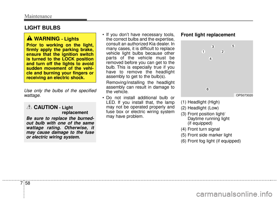
may have problem.Front light replacement
(1) Headlight (High)
(2) Headlight (Low)
(3) Front position light/ Daytime running light
(if equipped)
(4) Front turn signal
(5) Front side marker light
(6) Front fog light (if equipped)
WARNING - Lights
Prior to working on the light,
firmly apply the parking brake,
ensure that the ignition switch
is turned to the LOCK position
and turn off the lights to avoid
sudden movement of the vehi-
cle and burning your fingers or
receiving an electric shock.
CAUTION- Light replacement
Be sure to replace the burned-out bulb with one of the samewattage rating. Otherwise, itmay cause damage to the fuseor electric wiring system.
OPS073020
Page 325 of 407

Maintenance
62
7
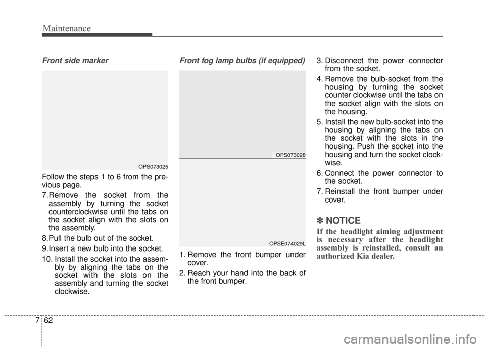
Front side marker
Follow the steps 1 to 6 from the pre-
vious page.
7.Remove the socket from the
assembly by turning the socket
counterclockwise until the tabs on
the socket align with the slots on
the assembly.
8.Pull the bulb out of the socket.
9.Insert a new bulb into the socket.
10. Install the socket into the assem- bly by aligning the tabs on the
socket with the slots on the
assembly and turning the socket
clockwise.
Front fog lamp bulbs (if equipped)
1. Remove the front bumper undercover.
2. Reach your hand into the back of the front bumper. 3. Disconnect the power connector
from the socket.
4. Remove the bulb-socket from the housing by turning the socket
counter clockwise until the tabs on
the socket align with the slots on
the housing.
5. Install the new bulb-socket into the housing by aligning the tabs on
the socket with the slots in the
housing. Push the socket into the
housing and turn the socket clock-
wise.
6. Connect the power connector to the socket.
7. Reinstall the front bumper under cover.
✽ ✽NOTICE
If the headlight aiming adjustment
is necessary after the headlight
assembly is reinstalled, consult an
authorized Kia dealer.
OPS073028
OPSE074029L
OPS073025
Page 341 of 407
Specifications & Consumer information
48
BULB WATTAGE
Light BulbWattageBulb type
Front Headlamps (High)
55H7LL
Headlamps (Low) 55H7LL
Front turn signal lamps LEDLED
Front position lamps LEDLED
Front fog lamps* 559006
Front day time running lamps*LEDLED
Front side marker 5W5W
Side Repeater lamps (Outside Mirror) LEDLED
Rear Rear tail,stop lamps and side marker
LEDLED
Rear tail lamps and side marker LEDLED
Rear turn signal lamps 27PY27W
Back-up lamps 16W16W
High mounted stop lamps LEDLED
License plate lamps 5W5W
Interior Map lamps
8FESTOON
Room lamps 8FESTOON
Vanity mirror lamps 5FESTOON
Glove box lamps 5FESTOON
Luggage lamp 8FESTOON
*: If equipped
Page 404 of 407

I5
Index
LCD Modes . . . . . . . . . . . . . . . . . . . . . . . . . . . . . . . 4-40
Service Mode . . . . . . . . . . . . . . . . . . . . . . . . . . . . . . 4-42
User Settings Mode . . . . . . . . . . . . . . . . . . . . . . . . . 4-43
Warning Messages . . . . . . . . . . . . . . . . . . . . . . . . . . 4-46
Light bulbs . . . . . . . . . . . . . . . . . . . . . . . . . . . . . . . . . . 7-58\
Front light replacement . . . . . . . . . . . . . . . . . . . . . . 7-58
High mounted stop light bulb replacement . . . . . . . 7-65
Interior light bulb replacement. . . . . . . . . . . . . . . . . 7-67
License plate light bulb replacement . . . . . . . . . . . . 7-66
Rear combination light bulb replacement . . . . . . . . 7-63
Side repeater light bulb replacement . . . . . . . . . . . . 7-63
Lighting. . . . . . . . . . . . . . . . . . . . . . . . . . . . . . . . . . . . \
. 4-75 Abnormal lamp operation . . . . . . . . . . . . . . . . . . . . 4-76
Abnormal lamp operation due to stabilization ofelectric control system . . . . . . . . . . . . . . . . . . . . . . 4-76
Battery saver function . . . . . . . . . . . . . . . . . . . . . . . 4-75
Daytime running light . . . . . . . . . . . . . . . . . . . . . . . 4-75
Front fog light . . . . . . . . . . . . . . . . . . . . . . . . . . . . . 4-80
Headlamp escort . . . . . . . . . . . . . . . . . . . . . . . . . . . . 4-75
High beam operation . . . . . . . . . . . . . . . . . . . . . . . . 4-78
Lighting control . . . . . . . . . . . . . . . . . . . . . . . . . . . . 4-76
Turn signals and lane change signals . . . . . . . . . . . . 4-79
Luggage volume . . . . . . . . . . . . . . . . . . . . . . . . . . . . . . . 8-3 Maintenance services . . . . . . . . . . . . . . . . . . . . . . . . . . . 7-3
Owner maintenance precautions . . . . . . . . . . . . . . . . 7-4
Owner’s responsibility . . . . . . . . . . . . . . . . . . . . . . . . 7-3
Mirrors . . . . . . . . . . . . . . . . . . . . . . . . . . . . . . . . . . . . \
. 4-29 Inside rearview mirror . . . . . . . . . . . . . . . . . . . . . . . 4-29
Outside rearview mirror . . . . . . . . . . . . . . . . . . . . . . 4-30
Motor number . . . . . . . . . . . . . . . . . . . . . . . . . . . . . . . . . 8-8
Motor room compartment. . . . . . . . . . . . . . . . . . . . . . . . 2-6
Owner maintenance . . . . . . . . . . . . . . . . . . . . . . . . . . . . 7-5 Owner maintenance schedule. . . . . . . . . . . . . . . . . . . 7-6
Parking assist system . . . . . . . . . . . . . . . . . . . . . . . . . . 4-70 Non-operational conditions of parking assist system . . 4-72
Operation of the parking assist system . . . . . . . . . . 4-70
Self-diagnosis . . . . . . . . . . . . . . . . . . . . . . . . . . . . . . 4-73
POWER button . . . . . . . . . . . . . . . . . . . . . . . . . . . . . . . . 5-5 Illuminated POWER button . . . . . . . . . . . . . . . . . . . . 5-5
Pedestrian Warning System . . . . . . . . . . . . . . . . . . . . 5-8
POWER button position . . . . . . . . . . . . . . . . . . . . . . . 5-5
Starting the vehicle. . . . . . . . . . . . . . . . . . . . . . . . . . . 5-7
Turing off the Vehicle. . . . . . . . . . . . . . . . . . . . . . . . . 5-9
Power electric specifications . . . . . . . . . . . . . . . . . . . . . 8-2M
O
P