2015 KIA PICANTO cooling
[x] Cancel search: coolingPage 390 of 846

Maintenance
58
7
SymbolFuse ratingProtected Component
MULTI FUSE80AEPS Control Module
125AAlternator, PCB Fuse & Relay Box
FUSE
50AI/P Junction Box (Power Connector Fuse : F1 10A / F2 20A,
Fuse : F24 10A / F25 10A / F26 10A / F27 15A, Tail Lamp Relay)
40AProjection Type : E/R Sub Fuse Box (Fuse : F1 10A / F2 20A / F4 15A / F5 10A / F7 10A )
50AI/P Junction Box (Fuse : F8 20A / F9 25A / F10 15A / F16 15A / F17 25A / F18 15A / F19 10A
/ F35 10A, Power Window Relay)
40AE/R Junction Box (Fuse : F11 15A), Ignition Switch, PDM Relay Box (ESCL Relay)
40AABS Control Relay, ESC Control Relay
30AABS Control Relay, ESC Control Relay
40ARear Defogger Relay
10AInstrument Cluster, Head Lamp RH, PCB Fuse & Relay Box (Head Lamp (HI) Relay)
15APCB Fuse & Relay Box (Fuel Pump #2 Relay)
40APCB Fuse & Relay Box (Start Relay), Ignition Switch, PDM Relay Box (ESCL Relay)
30APCB Fuse & Relay Box (Engine Control Relay, Fuse : F23 10A)
40APCB Fuse & Relay Box (Blower Relay)
40APCB Fuse & Relay Box (Cooling Fan Relay)
Engine compartment main fuse panel
Page 391 of 846

759
Maintenance
SymbolFuse ratingProtected Component
FUSE
(General head lamp type)
15APCB Fuse & Relay Box (Fuel Pump #1 Relay)
20APCB Fuse & Relay Box (Head Lamp (HI) Relay)
20APCB Fuse & Relay Box (Head Lamp (LO) Relay)
10APCB Fuse & Relay Box (Horn Relay, Burglar Alarm Horn Relay)
10APCB Fuse & Relay Box (A/C Relay)
10APCM (B3LA)
10ATCM (F3LA/F4LA/F3LA), PCM (B3LA)
10ATransaxle Range Switch, TCM/PCM, ESC Control Module, Rear Bumper Lamp,
Instrument Cluster, BCM, Back-Up Lamp LH/RH, Back-Up Lamp Switch
10AECM/PCM, Front Wiper Motor, Multifunction Switch
15ATCM/PCM, Injector #1/#2/#3, Injector #4 (G4LA), Jumper Wire 1, Crash Pad Switch (B4LA),
Fuel Pump #2 Relay (B3LA)
10AHead Lamp LH
10A
G3LA/G4LA/F3LA : TCM/ECM, Camshaft Position Sensor #1/#2, Oxygen Sensor (UP)/(DOWN),
Canister Purge Solenoid Valve, Oil Control Valve #1/#2, PCB Fuse & Relay Box (A/C Relay,
Cooling Fan Relay, Start Relay), B3LA : PCM, Camshaft Position Sensor #1/#2,
PCB Fuse & Relay Box (A/C Relay, Cooling Fan Relay), Oxygen Sensor (UP)/(DOWN),
Canister Purge Solenoid Valve, Oil Control Valve #1/#2, Variable Intake Solenoid Valve
10AHead Lamp RH
20AIgnition coil, condensor
Page 392 of 846

Maintenance
60
7
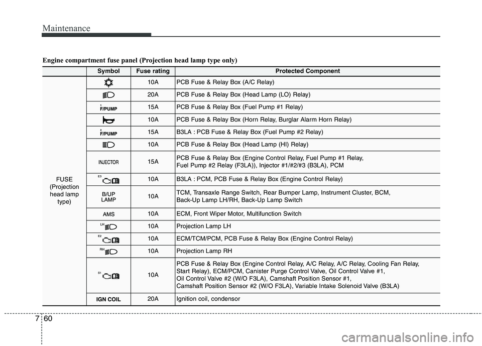
Engine compartment fuse panel (Projection head lamp type only)
SymbolFuse ratingProtected Component
FUSE
(Projection head lamp type)
10APCB Fuse & Relay Box (A/C Relay)
20APCB Fuse & Relay Box (Head Lamp (LO) Relay)
15APCB Fuse & Relay Box (Fuel Pump #1 Relay)
10APCB Fuse & Relay Box (Horn Relay, Burglar Alarm Horn Relay)
15AB3LA : PCB Fuse & Relay Box (Fuel Pump #2 Relay)
10APCB Fuse & Relay Box (Head Lamp (HI) Relay)
15APCB Fuse & Relay Box (Engine Control Relay, Fuel Pump #1 Relay,
Fuel Pump #2 Relay (F3LA)), Injector #1/#2/#3 (B3LA), PCM
10AB3LA : PCM, PCB Fuse & Relay Box (Engine Control Relay)
10ATCM, Transaxle Range Switch, Rear Bumper Lamp, Instrument Cluster, BCM,
Back-Up Lamp LH/RH, Back-Up Lamp Switch
10AECM, Front Wiper Motor, Multifunction Switch
10AProjection Lamp LH
10AECM/TCM/PCM, PCB Fuse & Relay Box (Engine Control Relay)
10AProjection Lamp RH
10A
PCB Fuse & Relay Box (Engine Control Relay, A/C Relay, A/C Relay, Cooling Fan Relay,
Start Relay), ECM/PCM, Canister Purge Control Valve, Oil Control Valve #1,
Oil Control Valve #2 (W/O F3LA), Camshaft Position Sensor #1,
Camshaft Position Sensor #2 (W/O F3LA), Variable Intake Solenoid Valve (B3LA)
20AIgnition coil, condensor
Page 420 of 846

I3
Index
Cargo weight ..................................................................5-56
Central door lock switch ................................................4-17
Changing tires ..................................................................6-9Chains
Tire chains ................................................................5-45
Checking tire inflation pressure ......................................7-41
Child restraint system ....................................................3-28 Lap belt......................................................................3-31
Lap/shoulder belt ......................................................3-30
Child-protector rear door lock ........................................4-18
Climate control system (Automatic) ..............................4-92 Air conditioning ........................................................4-97
Automatic heating and air conditioning....................4-93
Manual heating and air conditioning ........................4-94
Climate control system (Manual) ..................................4-83 Air conditioning ........................................................4-88
Climate control air filter............................................4-90
Heating and air conditioning ....................................4-84
Cigarette lighter ............................................................4-103
Climate control air filter ........................................4-90, 7-32
Clock (Digital) ..............................................................4-106
Clothes hanger ..............................................................4-108
Combined instrument, see instrument cluster ................4-42
Coolant ............................................................................7-23
Cooling fluid, see engine coolant ..................................7-23
Crankcase emission control system ................................7-75
Cup holder ....................................................................4-104
Curtain air bag ................................................................3-52 Dashboard, see instrument cluster ..................................4-42
Daytime running light ....................................................4-69
Declaration of conformity ................................................8-8
Defogging (Windshield) ................................................4-99
Defogging logic (Windshield) ......................................4-101
Defroster (Rear window) ................................................4-82
Defrosting (Windshield) ................................................4-99
Digital clock..................................................................4-106
Dimensions ......................................................................8-2
Displays, see instrument cluster ....................................4-42
Door locks ......................................................................4-15
Central door lock switch ..........................................4-17
Child-protector rear door lock ..................................4-18
Drink holders, see cup holders ....................................4-104
Driver's air bag ................................................................3-46
Driving at night ..............................................................5-41
Driving in flooded areas ................................................5-43
Driving in the rain ..........................................................5-42D
Page 581 of 846

Features of your vehicle
82
4
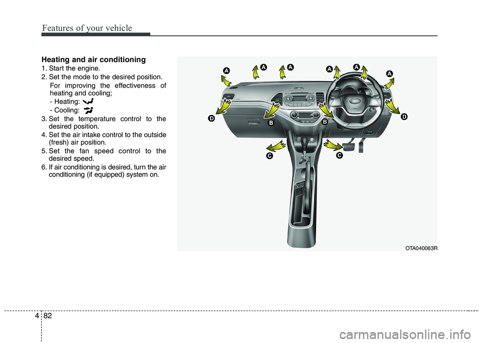
Heating and air conditioning
1. Start the engine.
2. Set the mode to the desired position.
For improving the effectiveness of heating and cooling;- Heating: - Cooling:
3. Set the temperature control to the desired position.
4. Set the air intake control to the outside (fresh) air position.
5. Set the fan speed control to the desired speed.
6. If air conditioning is desired, turn the air conditioning (if equipped) system on.
OTA040063R
Page 586 of 846

487
Features of your vehicle
System operation
Ventilation
1. Set the mode to the position.
2. Set the air intake control to the outside(fresh) air position.
3. Set the temperature control to the desired position.
4. Set the fan speed control to the desired speed.
Heating
1. Set the mode to the position.
2. Set the air intake control to the outside(fresh) air position.
3. Set the temperature control to the desired position.
4. Set the fan speed control to the desired speed.
5. If dehumidified heating is desired, turn the air conditioning system (if equipped) on.
If the windscreen fogs up, set the mode to the or
position. Operation Tips
To keep dust or unpleasant fumes from
entering the vehicle through the venti-
lation system, temporarily set the air
intake control to the recirculated air
position. Be sure to return the control
to the fresh air position when the irrita-
tion has passed to keep fresh air in the
vehicle. This will help keep the driver
alert and comfortable.
Air for the heating/cooling system is drawn in through the grilles just ahead
of the windscreen. Care should be
taken that these are not blocked by
leaves, snow, ice or other obstructions.
To prevent interior fog on the wind- screen, set the air intake control to the
fresh air position and fan speed to the
desired position, turn on the air condi-tioning system, and adjust the temper-
ature control to desired temperature.
Air conditioning
Kia Air Conditioning Systems are filled
with environmentally friendly R-134a
refrigerant.
1. Start the engine. Press the air condi- tioning button.
2. Set the mode to the position.
3. Set the air intake control to the outside air or recirculated air position.
4. Adjust the fan speed control and tem- perature control to maintain maximum
comfort.
When maximum cooling is desired, set the temperature control to the extreme
left position, then set the fan speedcontrol to the highest speed.
Page 587 of 846

Features of your vehicle
88
4
✽✽
NOTICE
When using the air conditioning sys- tem, monitor the temperature gauge
closely whilst driving up hills or in
heavy traffic when outside tempera-
tures are high. Air conditioning sys-
tem operation may cause engine over-
heating. Continue to use the blower
fan but turn the air conditioning sys-
tem off if the temperature gauge indi-
cates engine overheating.
When opening the windows in humid weather air conditioning may create
water droplets inside the vehicle.
Since excessive water droplets may
cause damage to electrical equipment,
air conditioning should only be used
with the windows closed.Air conditioning system operation tips
If the vehicle has been parked in direct
sunlight during hot weather, open the
windows for a short time to let the hot
air inside the vehicle escape.
To help reduce moisture inside of the windows on rainy or humid days,
decrease the humidity inside the vehi-
cle by operating the air conditioningsystem.
During air conditioning system opera- tion, you may occasionally notice aslight change in engine speed as the
air conditioning compressor cycles.
This is a normal system operation
characteristic.
Use the air conditioning system every month only for a few minutes to ensure
maximum system performance. When using the air conditioning sys-
tem, you may notice clear water drip-
ping (or even puddling) on the ground
under the passenger side of the vehi-
cle. This is a normal system operation
characteristic.
Operating the air conditioning system in the recirculated air position provides
maximum cooling, however, continual
operation in this mode may cause the
air inside the vehicle to become stale.
During cooling operation, you may occasionally notice a misty air flow
because of rapid cooling and humid air
intake. This is a normal system opera-
tion characteristic.
If you operate air conditioner exces- sively, the difference between the tem-
perature of the outside air and that ofthe windscreen could cause the outer
surface of the windscreen to fog up,
causing loss of visibility. In this case,
set the mode selection knob or button
to the position and fan speed con-
trol to the lower speed.
Page 591 of 846

Features of your vehicle
92
4
✽✽
NOTICE
Never place anything over the sensor
located on the instrument panel to
ensure better control of the heating and
cooling system.
Manual heating and air condition- ing The heating and cooling system can be
controlled manually by pushing buttons
other than the AUTO button. In this case,
the system works sequentially according
to the order of buttons selected.
When pressing any button (or turning any
knob) except the AUTO button whilst using
automatic operation, the functions not
selected will be controlled automatically.
1. Start the engine.
2. Set the mode to the desired position.
To improve the effectiveness of heat-ing and cooling:
- Heating:- Cooling:
3. Set the temperature control to the desired position.
4. Set the air intake control to the outside (fresh) air position.
5. Set the fan speed control to the desired speed.
6. If air conditioning is desired, turn the air conditioning system on.
Press the AUTO button in order to convert to full automatic control of the system.
Mode selection
The mode selection button controls the
direction of the air flow through the venti-lation system.
The air flow outlet port is converted as
follows:
Refer to the illustration in the “Manual cli- mate control system”.
OTA040072ROTA040071/H