2015 KIA PICANTO ECO mode
[x] Cancel search: ECO modePage 135 of 846

Features of your vehicle
62
4
ESC indicator (Electronic
Stability Control) (if equipped)
The ESC indicator will illuminate when
the ignition switch is turned ON, but
should go off after approximately 3 sec-
onds. When the ESC is on, it monitors
the driving conditions. Under normal driv-
ing conditions, the ESC indicator will
remain off. When a slippery or low trac-tion condition is encountered, the ESC
will operate, and the ESC indicator will
blink to indicate the ESC is operating. But, if the ESC system malfunctions the
indicator illuminates and stays on. In this
case, we recommend that you have the
vehicle inspected by an authorized Kia
dealer.
ESC OFF indicator
(if equipped)
The ESC OFF indicator will illuminate
when the ignition switch is turned ON,
but should go off after approximately 3
seconds. To switch to ESC OFF mode,
press the ESC OFF button. The ESCOFF indicator will illuminate indicating
the ESC is deactivated.
KEY OUT indicator (if equipped)
When the ENGINE START/STOP button
is in the ACC or ON position, if any door
is open, the system checks for the smart
key. If the smart key is not in the vehicle,
the indicator will blink, and if all doors are
closed, the chime will also sound for
about 5 seconds. The indicator will go off
while the vehicle is moving. Keep the
smart key in the vehicle.
Key reminder warning chime (if equipped)
Without smart key system
If the driver’s door is opened while the
ignition key is left in the ignition switch
(ACC or LOCK position), the key
reminder warning chime will sound. This
is to prevent you from locking your keys
in the vehicle. The chime sounds until the
key is removed from the ignition switch or
the driver’s door is closed.
With smart key system
If the driver’s door is opened while the
smart key is in the vehicle with the
engine start/stop button in ACC, the key
reminder warning chime will sound.
The chime sounds until the driver’s door is closed.
KEY
OUT
Page 137 of 846

Features of your vehicle
64
4
Auto stop indicator
(if equipped)
This indicator will illuminate when the engine enters the Idle Stop mode of theISG (Idle Stop and Go) system.
When the automatic starting occurs, the auto stop indicator on the cluster will
blink for 5 seconds.
For more details, refer to the ISG (Idle Stop and Go) system in chapter 5.
✽✽ NOTICE
When the engine automatically starts by
the ISG system, some warning lights
(ABS, ESC, ESC OFF, EPS or Parking
brake warning light) may turn on for a
few seconds.
This happens because of the low battery
voltage. It does not mean the system is
malfunctioning.
Low tire pressure indicator / TPMS malfunction indica-tor (if equipped)
The low tire pressure telltale comes on
for 3 seconds after the ignition switch is
turned to the "ON" position.
The low tire pressure telltale illuminates
when one or more of your tires is signifi-
cantly underinflated.
The low tire pressure telltale will illumi-
nate after it blinks for approximately one
minute when there is a problem with the
Tire Pressure Monitoring System.
In this case, we recommend that you
have the vehicle inspected by an author-
ized Kia dealer as soon as possible.
If the warning light illuminates while driv-
ing, reduce vehicle speed immediately
and stop the vehicle. Avoid hard braking
and overcorrecting at the steering wheel.Inflate the tires to the proper pressure as
indicated on the vehicle’s tire informationplacard.
WARNING - Low tire pres-
sure
Significantly low tire pressure
makes the vehicle unstable and can
contribute to loss of vehicle controland increased braking distances.
Continued driving on low pressure
tires will cause the tires to overheatand fail.
WARNING - Safe stopping
The TPMS cannot alert you to severe and sudden tire damage
caused by external factors.
If you feel any vehicle instability, immediately take your foot off the
accelerator, apply the brakes
gradually and with light force,
and slowly move to a safe posi-
tion off the road.
Page 158 of 846
485
Features of your vehicle
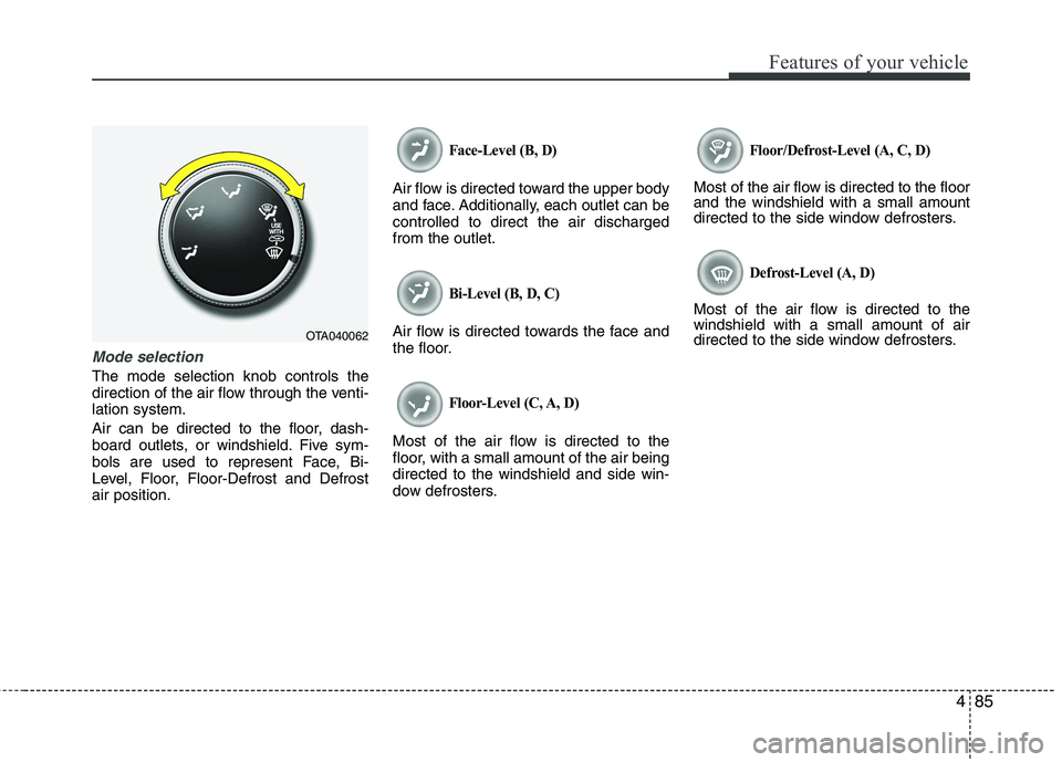
Mode selection
The mode selection knob controls the
direction of the air flow through the venti-lation system.
Air can be directed to the floor, dash-
board outlets, or windshield. Five sym-
bols are used to represent Face, Bi-
Level, Floor, Floor-Defrost and Defrostair position.
Face-Level (B, D)
Air flow is directed toward the upper body
and face. Additionally, each outlet can becontrolled to direct the air dischargedfrom the outlet.
Bi-Level (B, D, C)
Air flow is directed towards the face and
the floor.
Floor-Level (C, A, D)
Most of the air flow is directed to the
floor, with a small amount of the air beingdirected to the windshield and side win-
dow defrosters.
Floor/Defrost-Level (A, C, D)
Most of the air flow is directed to the floor and the windshield with a small amount
directed to the side window defrosters.
Defrost-Level (A, D)
Most of the air flow is directed to thewindshield with a small amount of air
directed to the side window defrosters.
OTA040062
Page 163 of 846
Features of your vehicle
90
4
Air conditioning system operation tips
If the vehicle has been parked in direct
sunlight during hot weather, open the
windows for a short time to let the hot
air inside the vehicle escape.
To help reduce moisture inside of the windows on rainy or humid days,
decrease the humidity inside the vehi-
cle by operating the air conditioningsystem.
During air conditioning system opera- tion, you may occasionally notice aslight change in engine speed as the
air conditioning compressor cycles.
This is a normal system operation
characteristic.
Use the air conditioning system every month only for a few minutes to ensure
maximum system performance. When using the air conditioning sys-
tem, you may notice clear water drip-
ping (or even puddling) on the ground
under the passenger side of the vehi-
cle. This is a normal system operation
characteristic.
Operating the air conditioning system in the recirculated air position provides
maximum cooling, however, continual
operation in this mode may cause the
air inside the vehicle to become stale.
During cooling operation, you may occasionally notice a misty air flow
because of rapid cooling and humid air
intake. This is a normal system opera-
tion characteristic.
If you operate air conditioner exces- sively, the difference between the tem-
perature of the outside air and that ofthe windshield could cause the outer
surface of the windshield to fog up,
causing loss of visibility. In this case,
set the mode selection knob or button
to the position and fan speed con-
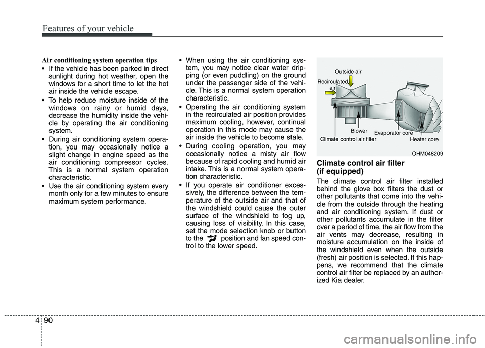
trol to the lower speed. Climate control air filter (if equipped) The climate control air filter installed
behind the glove box filters the dust or
other pollutants that come into the vehi-cle from the outside through the heating
and air conditioning system. If dust or
other pollutants accumulate in the filter
over a period of time, the air flow from the
air vents may decrease, resulting in
moisture accumulation on the inside of
the windshield even when the outside
(fresh) air position is selected. If this hap-
pens, we recommend that the climate
control air filter be replaced by an author-
ized Kia dealer.
OHM048209
Outside air
Recirculated air
Climate control air filter Blower
Evaporator core
Heater core
Page 167 of 846
Features of your vehicle
94
4
Manual heating and air condition- ing The heating and cooling system can be
controlled manually by pushing buttons
other than the AUTO button. In this case,
the system works sequentially according
to the order of buttons selected.
When pressing any button (or turning
any knob) except the AUTO button while
using automatic operation, the functionsnot selected will be controlled automati-
cally.
1. Start the engine.
2. Set the mode to the desired position.
To improve the effectiveness of heat-ing and cooling:
- Heating:- Cooling:
3. Set the temperature control to the desired position.
4. Set the air intake control to the outside (fresh) air position.
5. Set the fan speed control to the desired speed.
6. If air conditioning is desired, turn the air conditioning system on.
Press the AUTO button in order to con-
vert to full automatic control of the sys-tem.
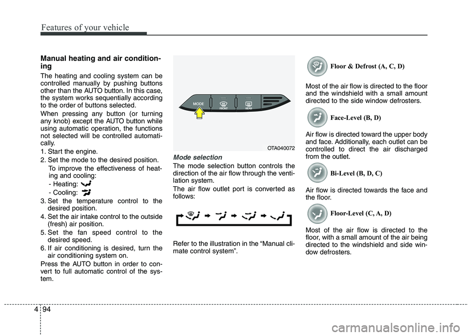
Mode selection
The mode selection button controls the
direction of the air flow through the venti-lation system.
The air flow outlet port is converted as
follows:
Refer to the illustration in the “Manual cli- mate control system”. Floor & Defrost (A, C, D)
Most of the air flow is directed to the floorand the windshield with a small amount
directed to the side window defrosters. Face-Level (B, D)
Air flow is directed toward the upper body
and face. Additionally, each outlet can becontrolled to direct the air dischargedfrom the outlet. Bi-Level (B, D, C)
Air flow is directed towards the face and
the floor. Floor-Level (C, A, D)
Most of the air flow is directed to the
floor, with a small amount of the air beingdirected to the windshield and side win-
dow defrosters.
OTA040072
Page 169 of 846
Features of your vehicle
96
4
Temperature conversion
You can switch the temperature mode
between Centigrade to Fahrenheit as fol-
lows:
While pressing the OFF button, press the
AUTO button for 4 seconds or more.
The display will change from Centigrade
to Fahrenheit, or from Fahrenheit to
Centigrade.
If the battery has been discharged or dis-
connected, the temperature mode dis-
play will reset to Centigrade.
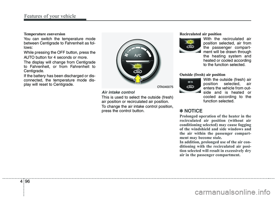
Air intake control
This is used to select the outside (fresh) air position or recirculated air position.
To change the air intake control position,
press the control button. Recirculated air position
With the recirculated airposition selected, air from
the passenger compart-
ment will be drawn throughthe heating system andheated or cooled according
to the function selected.
Outside (fresh) air position With the outside (fresh) airposition selected, air
enters the vehicle from out-side and is heated or
cooled according to thefunction selected.
✽✽ NOTICE
Prolonged operation of the heater in the
recirculated air position (without air
conditioning selected) may cause fogging
of the windshield and side windows and
the air within the passenger compart-
ment may become stale.
In addition, prolonged use of the air con-
ditioning with the recirculated air posi-
tion selected will result in excessively dry
air in the passenger compartment.
OTA040075
Page 183 of 846
Features of your vehicle
110
4
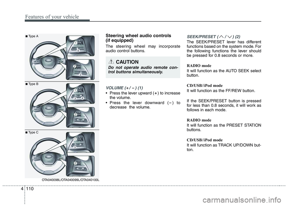
Steering wheel audio controls (if equipped)
The steering wheel may incorporate
audio control buttons.
VOLUME ( / ) (1)
• Press the lever upward ( ) to increase
the volume.
Press the lever downward ( ) to decrease the volume.
SEEK/PRESET ( / ) (2)
The SEEK/PRESET lever has different
functions based on the system mode. For
the following functions the lever should
be pressed for 0.8 seconds or more.
RADIO mode
It will function as the AUTO SEEK select
button.
CD/USB / i Pod mode
It will function as the FF/REW button.
If the SEEK/PRESET button is pressed
for less than 0.8 seconds, it will work as
follows in each mode.
RADIO mode
It will function as the PRESET STATION
buttons.
CD/USB / i Pod mode
It will function as TRACK UP/DOWN but- ton.
CAUTION
Do not operate audio remote con-
trol buttons simultaneously.
■ Type A
■Type B
■Type C
OTA040098L/OTA040099L/OTA040100L
Page 184 of 846
4111
Features of your vehicle
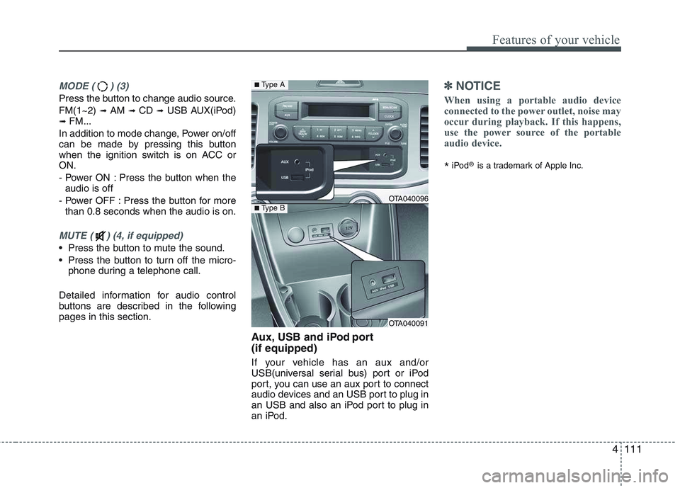
MODE ( ) (3)
Press the button to change audio source. FM(1~2) ➟ AM ➟ CD ➟ USB AUX(iPod)
➟ FM...
In addition to mode change, Power on/off
can be made by pressing this button
when the ignition switch is on ACC orON.
- Power ON : Press the button when the audio is off
- Power OFF : Press the button for more than 0.8 seconds when the audio is on.
MUTE ( ) (4, if equipped)
Press the button to mute the sound.
Press the button to turn off the micro- phone during a telephone call.
Detailed information for audio control
buttons are described in the followingpages in this section. Aux, USB and iPod port (if equipped)
If your vehicle has an aux and/or
USB(universal serial bus) port or iPod
port, you can use an aux port to connect
audio devices and an USB port to plug in
an USB and also an iPod port to plug in
an iPod.
✽✽NOTICE
When using a portable audio device
connected to the power outlet, noise may
occur during playback. If this happens,
use the power source of the portable
audio device.
* iPod
®
is a trademark of Apple Inc.
OTA040096
OTA040091
■Type A
■Type B