Page 165 of 420
Features of your vehicle
92 4
✽
✽
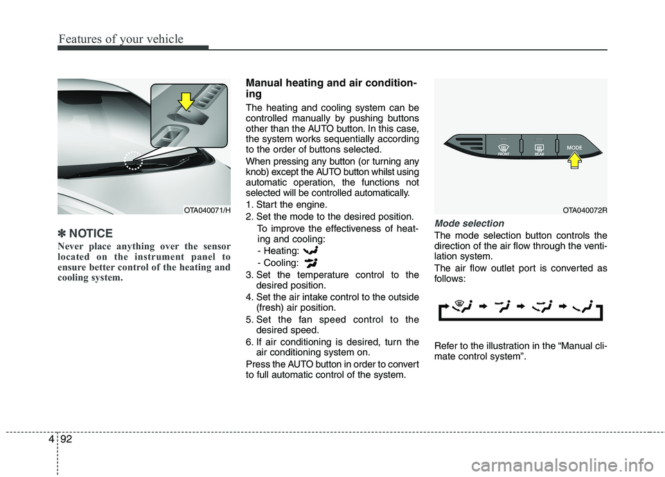
NOTICE
Never place anything over the sensor
located on the instrument panel to
ensure better control of the heating and
cooling system.
Manual heating and air condition-
ing
The heating and cooling system can be
controlled manually by pushing buttons
other than the AUTO button. In this case,
the system works sequentially according
to the order of buttons selected.
When pressing any button (or turning any
knob) except the AUTO button whilst using
automatic operation, the functions not
selected will be controlled automatically.
1. Start the engine.
2. Set the mode to the desired position.
To improve the effectiveness of heat-
ing and cooling:
- Heating:
- Cooling:
3. Set the temperature control to the
desired position.
4. Set the air intake control to the outside
(fresh) air position.
5. Set the fan speed control to the
desired speed.
6. If air conditioning is desired, turn the
air conditioning system on.
Press the AUTO button in order to convert
to full automatic control of the system.
Mode selection
The mode selection button controls the
direction of the air flow through the venti-
lation system.
The air flow outlet port is converted as
follows:
Refer to the illustration in the “Manual cli-
mate control system”.
OTA040072ROTA040071/H
Page 166 of 420
493
Features of your vehicle
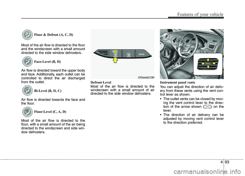
Floor & Defrost (A, C, D)
Most of the air flow is directed to the floor
and the windscreen with a small amount
directed to the side window defrosters.
Face-Level (B, D)
Air flow is directed toward the upper body
and face. Additionally, each outlet can be
controlled to direct the air discharged
from the outlet.
Bi-Level (B, D, C)
Air flow is directed towards the face and
the floor.
Floor-Level (C, A, D)
Most of the air flow is directed to the
floor, with a small amount of the air being
directed to the windscreen and side win-
dow defrosters.Defrost-Level
Most of the air flow is directed to the
windscreen with a small amount of air
directed to the side window defrosters.Instrument panel vents
You can adjust the direction of air deliv-
ery from these vents using the vent con-
trol lever as shown.
The outlet vents can be closed by mov-
ing the vent control lever to the direc-
tion of the arrow shown ( ) on the
lever.
The direction of air delivery can be
adjusted by moving vent control lever
to the direction preferred.
OTA040073ROTA040064R
Page 291 of 420
Driving your vehicle
50 5
Following distance
Stay at least twice as far behind the vehi-
cle ahead as you would when driving
your vehicle without a trailer. This can
help you avoid situations that require
heavy braking and sudden turns.
Passing
You’ll need more passing distance up
ahead when you’re towing a trailer. And,
because of the increased vehicle length,
you’ll need to go much farther beyond the
passed vehicle before you can return to
your lane.
Backing up
Hold the bottom of the steering wheel
with one hand. Then, to move the trailer
to the left, just move your hand to the left.
To move the trailer to the right, move your
hand to the right. Always back up slowly
and, if possible, have someone guide
you.
Making turns
When you’re turning with a trailer, make
wider turns than normal. Do this so your
trailer won’t strike soft shoulders, kerbs,
road signs, trees, or other objects. Avoid
jerky or sudden manoeuvres. Signal well
in advance.
Turn signals when towing a trailer
When you tow a trailer, your vehicle has
to have a different turn signal flasher and
extra wiring. The green arrows on your
instrument panel will flash whenever you
signal a turn or lane change. Properly
connected, the trailer lights will also flash
to alert other drivers you’re about to turn,
change lanes, or stop.
When towing a trailer, the green arrows
on your instrument panel will flash for
turns even if the bulbs on the trailer are
burned out. Thus, you may think drivers
behind you are seeing your signals
when, in fact, they are not. It’s important
to check occasionally to be sure the trail-
er bulbs are still working. You must also
check the lights every time you discon-
nect and then reconnect the wires.
Do not connect a trailer lighting system
directly to your vehicle’s lighting system.
Use only an approved trailer wiring har-
ness.
An authorised Kia dealer can assist you
in installing the wiring harness.
Driving on grades
Reduce the speed and shift to a lower
gear before you start down a long or
steep downgrade. If you don’t shift down,
you might have to use your brakes so
much that they would get hot and no
longer operate efficiently.
On a long uphill grade, shift down and
reduce your speed to around 45 mph (70
km/h) to reduce the possibility of engine
and transaxle overheating.
If your trailer weighs more than the max-
imum trailer weight without trailer brakes
and you have an automatic transaxle,
you should drive in D (Drive) when tow-
ing a trailer.
Operating your vehicle in D (Drive) when
towing a trailer will minimise heat build up
and extend the life of your transaxle.
WARNING
Failure to use an approved trailer
wiring harness could result in dam-
age to the vehicle electrical system
and/or personal injury.
Page 378 of 420
751
Maintenance
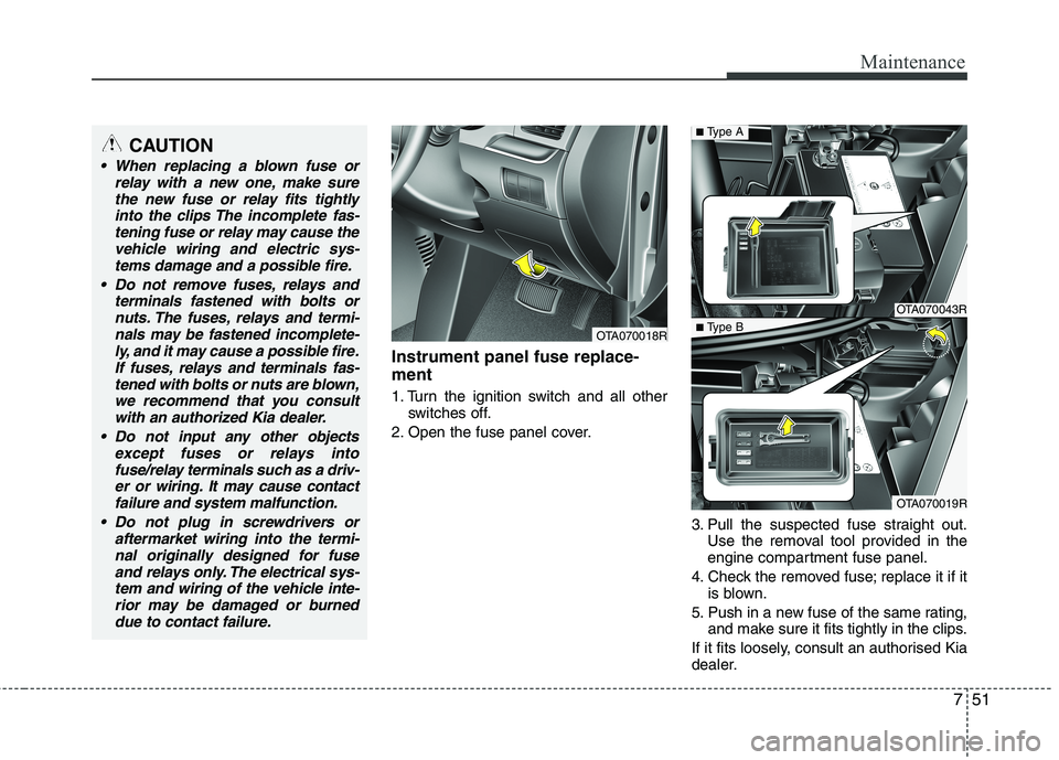
Instrument panel fuse replace-
ment
1. Turn the ignition switch and all other
switches off.
2. Open the fuse panel cover.
3. Pull the suspected fuse straight out.
Use the removal tool provided in the
engine compartment fuse panel.
4. Check the removed fuse; replace it if it
is blown.
5. Push in a new fuse of the same rating,
and make sure it fits tightly in the clips.
If it fits loosely, consult an authorised Kia
dealer.
OTA070018R
OTA070043R
OTA070019R
■Type A
■Type B
CAUTION
When replacing a blown fuse or
relay with a new one, make sure
the new fuse or relay fits tightly
into the clips The incomplete fas-
tening fuse or relay may cause the
vehicle wiring and electric sys-
tems damage and a possible fire.
Do not remove fuses, relays and
terminals fastened with bolts or
nuts. The fuses, relays and termi-
nals may be fastened incomplete-
ly, and it may cause a possible fire.
If fuses, relays and terminals fas-
tened with bolts or nuts are blown,
we recommend that you consult
with an authorized Kia dealer.
Do not input any other objects
except fuses or relays into
fuse/relay terminals such as a driv-
er or wiring. It may cause contact
failure and system malfunction.
Do not plug in screwdrivers or
aftermarket wiring into the termi-
nal originally designed for fuse
and relays only. The electrical sys-
tem and wiring of the vehicle inte-
rior may be damaged or burned
due to contact failure.
Page 381 of 420
Maintenance
54 7
✽
✽
NOTICE
Not all fuse panel descriptions in this
manual may be applicable to your vehi-
cle. It is accurate at the time of printing.
When you inspect the fuse panel in your
vehicle, refer to the fuse panel label.
Fuse/relay panel description
Inside the fuse/relay panel covers, you can find the fuse/relay label describing fuse/relay name and capacity.
Engine compartment fuse panel
OTA070023R/OTA070024R/OTA070041R
Instrument panel fuse panel
Engine compartment fuse panel
(Projection head lamp type only)
Page 382 of 420
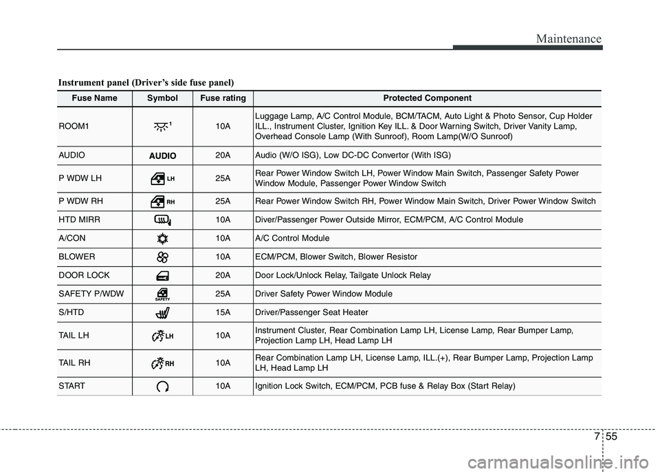
755
Maintenance
Fuse NameSymbolFuse ratingProtected Component
ROOM110ALuggage Lamp, A/C Control Module, BCM/TACM, Auto Light & Photo Sensor, Cup Holder
ILL., Instrument Cluster, Ignition Key ILL. & Door Warning Switch, Driver Vanity Lamp,
Overhead Console Lamp (With Sunroof), Room Lamp(W/O Sunroof)
AUDIO20AAudio (W/O ISG), Low DC-DC Convertor (With ISG)
P WDW LH25ARear Power Window Switch LH, Power Window Main Switch, Passenger Safety Power
Window Module, Passenger Power Window Switch
P WDW RH25ARear Power Window Switch RH, Power Window Main Switch, Driver Power Window Switch
HTD MIRR10ADiver/Passenger Power Outside Mirror, ECM/PCM, A/C Control Module
A/CON10AA/C Control Module
BLOWER10AECM/PCM, Blower Switch, Blower Resistor
DOOR LOCK20ADoor Lock/Unlock Relay, Tailgate Unlock Relay
SAFETY P/WDW25ADriver Safety Power Window Module
S/HTD15ADriver/Passenger Seat Heater
TAIL LH10AInstrument Cluster, Rear Combination Lamp LH, License Lamp, Rear Bumper Lamp,
Projection Lamp LH, Head Lamp LH
TAIL RH10ARear Combination Lamp LH, License Lamp, ILL.(+), Rear Bumper Lamp, Projection Lamp
LH, Head Lamp LH
START10AIgnition Lock Switch, ECM/PCM, PCB fuse & Relay Box (Start Relay)
Instrument panel (Driver’s side fuse panel)
Page 385 of 420

Maintenance
58 7
SymbolFuse ratingProtected Component
MULTI FUSE80AEPS Control Module
125AAlternator, PCB Fuse & Relay Box
FUSE
50AI/P Junction Box (Power Connector Fuse : F1 10A / F2 20A, Fuse : F24 10A / F25 10A / F26
10A / F27 15A, Tail Lamp Relay)
40AProjection Type : E/R Sub Fuse Box (Fuse : F1 10A / F2 20A / F4 15A / F5 10A / F7 10A )
50AI/P Junction Box (Fuse : F8 20A / F9 25A / F10 15A / F16 15A / F17 25A / F18 15A / F19 10A
/ F35 10A, Power Window Relay)
40AE/R Junction Box (Fuse : F11 15A), Ignition Switch, PDM Relay Box (ESCL Relay)
40AABS Control Relay, ESC Control Relay
30AABS Control Relay, ESC Control Relay
40ARear Defogger Relay
10AInstrument Cluster, Head Lamp RH, PCB Fuse & Relay Box (Head Lamp (HI) Relay)
15APCB Fuse & Relay Box (Fuel Pump #2 Relay)
40APCB Fuse & Relay Box (Start Relay), Ignition Switch, PDM Relay Box (ESCL Relay)
30APCB Fuse & Relay Box (Engine Control Relay, Fuse : F23 10A)
40APCB Fuse & Relay Box (Blower Relay)
40APCB Fuse & Relay Box (Cooling Fan Relay)
Engine compartment main fuse panel
Page 387 of 420

Maintenance
60 7
Engine compartment fuse panel (Projection head lamp type only)
SymbolFuse ratingProtected Component
FUSE
(Projection
head lamp
type)
10APCB Fuse & Relay Box (A/C Relay)
20APCB Fuse & Relay Box (Head Lamp (LO) Relay)
15APCB Fuse & Relay Box (Fuel Pump #1 Relay)
10APCB Fuse & Relay Box (Horn Relay, Burglar Alarm Horn Relay)
15AB3LA : PCB Fuse & Relay Box (Fuel Pump #2 Relay)
10APCB Fuse & Relay Box (Head Lamp (HI) Relay)
15APCB Fuse & Relay Box (Engine Control Relay, Fuel Pump #1 Relay,
Fuel Pump #2 Relay (F3LA)), Injector #1/#2/#3 (B3LA), PCM
10AB3LA : PCM, PCB Fuse & Relay Box (Engine Control Relay)
10ATCM, Transaxle Range Switch, Rear Bumper Lamp, Instrument Cluster, BCM,
Back-Up Lamp LH/RH, Back-Up Lamp Switch
10AECM, Front Wiper Motor, Multifunction Switch
10AProjection Lamp LH
10AECM/TCM/PCM, PCB Fuse & Relay Box (Engine Control Relay)
10AProjection Lamp RH
10A
PCB Fuse & Relay Box (Engine Control Relay, A/C Relay, A/C Relay, Cooling Fan Relay, Start
Relay), ECM/PCM, Canister Purge Control Valve, Oil Control Valve #1, Oil Control Valve #2
(W/O F3LA), Camshaft Position Sensor #1, Camshaft Position Sensor #2 (W/O F3LA),
Variable Intake Solenoid Valve (B3LA)
20AIGN COIL, Condensor