Page 3 of 452

ii
1
2
3
4
5
6
7
8I
IntroductionHow to use this manual / Fuel requirements / Vehicle break-in process
Your vehicle at a glance
Exterior overview / Interior overview / Instrument panel overview / Engi\
ne compartment
Safety features of your vehicle
Seats / Seat belts / Child restraint system / Air bag
Features of your vehicleKeys / Door locks / Tailgate / Windows / Hood / Fuel filler lid / Panoramic sunroof / Steering wheel / Mirrors/ Instrument cluster / Lighting / Wipers & Washers / Climate control system / Audio system / Etc.
Driving your vehicleBefore driving / Engine start/stop button / Transaxle / Brake system / Cruise control system /
Active ECO system / Winter driving / Vehicle load limit / Etc.
What to do in an emergencyRoad warning / Emergency while driving / Emergency starting / Engine overheat / Flat tire / Towing / Etc.
MaintenanceEngine compartment / Maintenance service / Engine oil / Engine coolant /\
Brake fluid / Washer fluid /
Parking brake / Air cleaner / Wiper blades / Battery / Tire and wheels / Fuses / Etc.
Specifications & Consumer information
Index
table of contents
Page 15 of 452
Your vehicle at a glance
62
ENGINE COMPARTMENT
OYDNMC2041/OYDNMC2067
■
■1.8 / 2.0 Gasoline engine
❈The actual engine compartment in the vehicle may differ from the illustration.
■
■1.6 Turbo GDI engine
1. Engine oil filler cap ...........................7-29
2. Engine oil dipstick .............................7-29
3. Brake/clutch fluid reservoir ...............7-34
4. Air cleaner.........................................7-36
5. Fuse box ...........................................7-58
6. Positive battery terminal ...................7-41
7. Negative battery terminal..................7-41
8. Windshield washer fluid reservoir .....7-35
9. Radiator cap .....................................7-32
10. Engine coolant reservoir .................7-31
Page 55 of 452

Safety features of your vehicle
40
3
✽
✽
NOTICE
Before you replace a fuse or discon-
nect a battery terminal, turn the igni-
tion switch to the LOCK position
and remove the ignition key. Never
remove or replace the air bag related
fuse(s) when the ignition switch is in
the ON position. Failure to heed this
warning will cause the SRS air bag
warning light to illuminate.
Occupant detection system
Your vehicle is equipped with an occu-
pant detection system in the front
passenger's seat.
The occupant detection system is
designed to detect the presence of a
properly-seated front passenger and
determine if the passenger's front air
bag should be enabled (may inflate)
or not. The driver's front air bag is not
affected or controlled by the occu-
pant detection system.
B240B05L
Passenger’s front air bag
WARNING - Air bag
obstructions
Do not install or place any
accessories on the steering
wheel, instrument panel, or on
the front passenger's panel
above the glove box in a vehicle
Such objects may become dan-
gerous projectiles if the air bag
deploys.
OYDNSA2037
Page 111 of 452

Features of your vehicle
40
4
Resetting the sunroof
Whenever the vehicle battery is dis-
connected or discharged, or related
fuse is blown, you must reset your
sunroof system as follows:
1. Turn the ignition switch to the ON
position or start the engine. We
recommend resetting the sunroof
while the engine is running.
2. Push and release the control lever forward in the direction of close
repeatedly until the sunroof does
not move. Sunroof will stop at the
close position or the tilt position
depends on the sunroof condition.
3. Release the control lever when sunroof does not move. 4. Push the control lever forward in the
direction of close about 10 seconds.
- When the sunroof is in the close position :
Glass will tilt up then will move up
and down slightly.
- When the sunroof is in the tilt position:
Glass will move up and down
slightly.
5. Within 3 seconds, push the sun- roof control lever forward in the
direction of close until the sunroof
operates as follows:
Tilt down → Slide Open →
Slide Close.
✽ ✽ NOTICE
Do not release the lever until the
operation is completed.
If you release the lever during oper-
ation, try again from step 2.
6. Release the sunroof control lever
after all operation has completed.
(The sunroof system has been
reset.)
❈ For more detailed information,
contact an authorized Kia dealer.
✽ ✽
NOTICE
If the sunroof is not reset when the
vehicle battery is disconnected or
discharged, or related fuse is blown,
the sunroof may operate improperly.
Page 133 of 452

Features of your vehicle
62
4
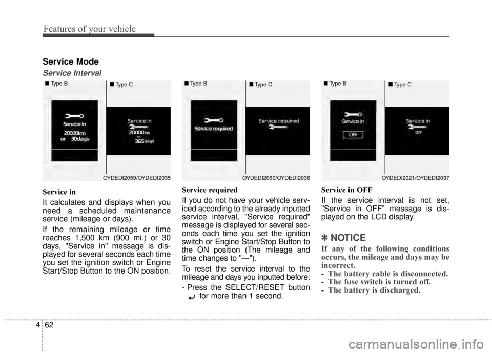
Service Mode
Service Interval
Service in
It calculates and displays when you
need a scheduled maintenance
service (mileage or days).
If the remaining mileage or time
reaches 1,500 km (900 mi.) or 30
days, "Service in" message is dis-
played for several seconds each time
you set the ignition switch or Engine
Start/Stop Button to the ON position. Service required
If you do not have your vehicle serv-
iced according to the already inputted
service interval, "Service required"
message is displayed for several sec-
onds each time you set the ignition
switch or Engine Start/Stop Button to
the ON position (The mileage and
time changes to "---").
To reset the service interval to the
mileage and days you inputted before:
- Press the SELECT/RESET button
for more than 1 second. Service in OFF
If the service interval is not set,
"Service in OFF" message is dis-
played on the LCD display.
✽ ✽
NOTICE
If any of the following conditions
occurs, the mileage and days may be
incorrect.
- The battery cable is disconnected.
- The fuse switch is turned off.
- The battery is discharged.
OYDEDI2059/OYDEDI2035
■
Type B
■Type COYDEDI2060/OYDEDI2036
■
Type B
■Type COYDEDI2021/OYDEDI2037
■
Type B
■Type C
Page 215 of 452
Features of your vehicle
144
4
LCD monitor
(clock and outside temperature)Whenever the battery terminals or
related fuses are disconnected, you
must reset the time.
When the ignition switch is in the
ACC or ON position, the clock but-
tons operate as follows:
Pressing the 'H" button will advance
the time display by one hour.
Pressing the "M" button will advance
the time display by one minute.
- Clock
To change the 12 hour format to
the 24 hour format, press the "H"
and "M" button at the same time for
more than 4 seconds.
For example, if the time is 10:15
p.m., the display will change to
22:15.
- Outside thermometer
To change the temperature unit F
to C (or C to F) press the "H" and
"M" button at the same time for 1 to
3 seconds.
WARNING
Do not adjust the clock while
driving. You may lose your steer-
ing control.
OYDECO2062
Page 285 of 452
Driving your vehicle
12
5
If the battery is weak or the smart
key does not work correctly, you
can start the engine by pressing
the engine start/stop button with
the smart key.
When the stop lamp fuse is blown, you can not start the engine nor-
mally. Replace the fuse with a new
one. If it is not possible, you can
start the engine by pressing the
ENGINE START/STOP button for
10 seconds while it is in the ACC
position. The engine can start with-
out depressing the brake pedal.
But for your safety always depress
the brake pedal before starting the
engine. Do not press the ENGINE START/
STOP button for more than 10 sec-
onds except when the stop lamp fuse
is blown.
OYDDDR3006
Page 356 of 452

Fuses . . . . . . . . . . . . . . . . . . . . . . . . . . . . . . . . . . . . \
7-58
• Instrument panel fuse replacement . . . . . . . . . . . . . . 7-59
• Engine compartment fuse replacement. . . . . . . . . . . 7-61
• Fuse/relay panel description. . . . . . . . . . . . . . . . . . . . 7-63
• Engine compartment fuse panel . . . . . . . . . . . . . . . . 7-64
• Engine room (Battery terminal cover) . . . . . . . . . . . 7-65
Appearance care . . . . . . . . . . . . . . . . . . . . . . . . . . . 7-71
• Exterior care . . . . . . . . . . . . . . . . . . . . . . . . . . . . . . . . 7-71
• Interior care . . . . . . . . . . . . . . . . . . . . . . . . . . . . . . . . . 7-76
Emission control system . . . . . . . . . . . . . . . . . . . . 7-78
• Crankcase emission control system . . . . . . . . . . . . . . 7-78
• Evaporative emission control
(including ORVR: Onboard Refueling Vapor
Recovery) system . . . . . . . . . . . . . . . . . . . . . . . . . . . 7-78
• Exhaust emission control system . . . . . . . . . . . . . . . . 7-79
7