Page 176 of 695
When a door is open and the interior lights are on,
rotating the dimmer control to the extreme bottom posi-
tion will cause all the interior lights to turn off. This is
also known as the “Party” mode because it allows the
doors to stay open for extended periods of time without
discharging the vehicle’s battery.
WINDSHIELD WIPERS AND WASHERS
The windshield wiper/washer control lever is located on
the right side of the steering column. The front wipers are
operated by rotating a switch, located at the end of the
lever. For information on using the rear window wiper/
washer, refer to “Rear Window Features” in “Under-
standing The Features Of Your Vehicle”.
Rear Cargo Light
174 UNDERSTANDING THE FEATURES OF YOUR VEHICLE
Page 308 of 695

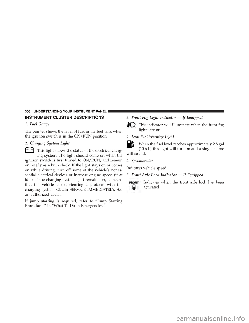
INSTRUMENT CLUSTER DESCRIPTIONS
1. Fuel Gauge
The pointer shows the level of fuel in the fuel tank when
the ignition switch is in the ON/RUN position.
2. Charging System Light
This light shows the status of the electrical charg-
ing system. The light should come on when the
ignition switch is first turned to ON/RUN, and remain
on briefly as a bulb check. If the light stays on or comes
on while driving, turn off some of the vehicle’s nones-
sential electrical devices or increase engine speed (if at
idle). If the charging system light remains on, it means
that the vehicle is experiencing a problem with the
charging system. Obtain SERVICE IMMEDIATELY. See
an authorized dealer.
If jump starting is required, refer to “Jump Starting
Procedures” in “What To Do In Emergencies”.
3. Front Fog Light Indicator — If Equipped
This indicator will illuminate when the front fog
lights are on.
4. Low Fuel Warning Light
When the fuel level reaches approximately 2.8 gal
(10.6 L) this light will turn on and a single chime
will sound.
5. Speedometer
Indicates vehicle speed.
6. Front Axle Lock Indicator — If Equipped
Indicates when the front axle lock has been
activated.
306 UNDERSTANDING YOUR INSTRUMENT PANEL
Page 392 of 695

external USB device may take a few minutes to connect),
the audio device starts charging and is ready for use by
pushing radio switches, as described below.
NOTE:If the audio device battery is completely dis-
charged, it may not communicate with the iPod®/USB/
MP3 control system until a minimum charge is attained.
Leaving the audio device connected to the iPod®/USB/
MP3 control system may charge it to the required level.
Using This Feature
By using an iPod® cable, or an external USB device to
connect to the USB port:
•The audio device can be played on the vehicle’s sound
system, providing metadata (artist, track title, album,
etc.) information on the radio display.
•The audio device can be controlled using the radio
buttons to Play, Browse, and List the iPod® contents.
•The audio device battery charges when plugged into
the USB/AUX connector (if supported by the specific
audio device).
Controlling The iPod® Or External USB Device
Using Radio Buttons
To get into the iPod®/USB/MP3 control mode and
access a connected audio device, either push the “AUX”
button on the radio faceplate or push the VR button and
say#USB#or#Switch to USB.#Once in the iPod®/USB/
MP3 control mode, audio tracks (if available from audio
device) start playing over the vehicle’s audio system.
Play Mode
When switched to iPod®/USB/MP3 control mode, the
iPod® or external USB device automatically starts Play
390 UNDERSTANDING YOUR INSTRUMENT PANEL
Page 574 of 695

3. If using another vehicle to jump-start the battery, park
the vehicle within the jumper cables reach, set the
parking brake and make sure the ignition is OFF.
WARNING!
Do not allow vehicles to touch each other as this
could establish a ground connection and personal
injury could result.
Jump-Starting Procedure
WARNING!
Failure to follow this jump-starting procedure could
result in personal injury or property damage due to
battery explosion.
CAUTION!
Failure to follow these procedures could result in
damage to the charging system of the booster vehicle
or the discharged vehicle.
Connecting The Jumper Cables
1. Connect the positive(+)end of the jumper cable to the
positive(+)post of the discharged vehicle.
2. Connect the opposite end of the positive(+)jumper
cable to the positive(+)post of the booster battery.
3. Connect the negative(-)end of the jumper cable to the
negative(-)post of the booster battery.
4. Connect the opposite end of the negative(-)jumper
cable to a good engine ground (exposed metal part of
the discharged vehicle’s engine) away from the battery
and the fuel injection system.
572 WHAT TO DO IN EMERGENCIES
Page 575 of 695

WARNING!
Do not connect the jumper cable to the negative (-) post
of the discharged battery. The resulting electrical spark
could cause the battery to explode and could result in
personal injury. Only use the specific ground point, do
not use any other exposed metal parts.
5. Start the engine in the vehicle that has the booster
battery, let the engine idle a few minutes, and then
start the engine in the vehicle with the discharged
battery.
6. Once the engine is started, remove the jumper cables
in the reverse sequence:
Disconnecting The Jumper Cables
1. Disconnect the negative(-)end of the jumper cable
from the engine ground of the vehicle with the dis-
charged battery.
2. Disconnect the opposite end of the negative(-)jumper
cable from the negative(-)post of the booster battery.
3. Disconnect the positive(+)end of the jumper cable
from the positive(+)post of the booster battery.
4. Disconnect the opposite end of the positive(+)jumper
cable from the positive(+)post of the vehicle with the
discharged battery.
If frequent jump-starting is required to start your vehicle
you should have the battery and charging system in-
spected at your authorized dealer.
CAUTION!
Accessories plugged into the vehicle power outlets
draw power from the vehicle’s battery, even when not
in use (i.e., cellular phones, etc.). Eventually, if
plugged in long enough without engine operation,
(Continued)
6
WHAT TO DO IN EMERGENCIES 573