Page 390 of 695

SETUP Button
Pushing the SETUP button allows you to select the
following items:
•Display Sirius ID number — Push the AUDIO/
SELECT button to display the Sirius ID number. This
number is used to activate, deactivate, or change the
Sirius subscription.
SET Button — To Set The Pushbutton Memory
When you are receiving a channel that you wish to
commit to pushbutton memory, push the SET button. The
symbol SET 1 will now show in the display window.
Select the button (1-6) you wish to lock onto this channel
and push and release that button. If a button is not
selected within five seconds after pushing the SET but-
ton, the channel will continue to play but will not be
stored into pushbutton memory.
You may add a second channel to each pushbutton by
repeating the above procedure with this exception: Push
the SET button twice and SET 2 will show in the display
window. Each button can be set for SET 1 and SET 2. This
allows a total of 12 Satellite channels to be stored into
pushbutton memory. The channels stored in SET 2
memory can be selected by pushing the pushbutton
twice.
Every time a preset button is used, a corresponding
button number will display.
Buttons1-6
These buttons tune the radio to the channels that you
commit to pushbutton memory (12 Satellite stations).
Operating Instructions (Uconnect® Phone) — If
Equipped
Refer to “Uconnect® Phone” in “Understanding The
Features Of Your Vehicle”.
388 UNDERSTANDING YOUR INSTRUMENT PANEL
Page 391 of 695

iPod®/USB/MP3 CONTROL — IF EQUIPPED
This feature allows an iPod® or external USB device to be
plugged into the USB port, located in the center console.
iPod® control supports Mini, 4G, Photo, Nano, 5G iPod®
and iPhone® devices. Some iPod® software versions
may not fully support the iPod® control features. Please
visit Apple’s website for software updates.
NOTE:
•If the radio has a USB port, refer to the appropriate
Uconnect® Supplement Manual for iPod® or external
USB device support capability.
•Connecting an iPod® or consumer electronic audio
device to the AUX port located in the radio faceplate,
plays media, but does not use the iPod®/MP3 control
feature to control the connected device.
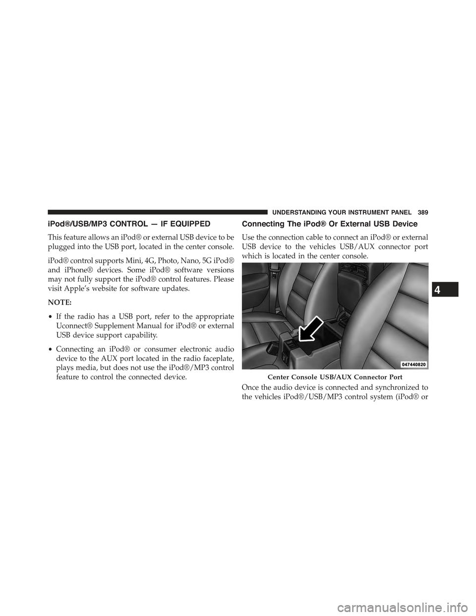
Connecting The iPod® Or External USB Device
Use the connection cable to connect an iPod® or external
USB device to the vehicles USB/AUX connector port
which is located in the center console.
Once the audio device is connected and synchronized to
the vehicles iPod®/USB/MP3 control system (iPod® or
Center Console USB/AUX Connector Port
4
UNDERSTANDING YOUR INSTRUMENT PANEL 389
Page 396 of 695
CAUTION!
•Leaving the iPod® or external USB device (or any
supported device) anywhere in the vehicle in ex-
treme heat or cold can alter the operation or dam-
age the device. Follow the device manufacturer ’s
guidelines.
•Placing items on the iPod® or external USB device,
or connections to the iPod® or external USB device
in the vehicle, can cause damage to the device
and/or to the connectors.
WARNING!
Do not plug in or remove the iPod® or external USB
device while driving. Failure to follow this warning
could result in an accident.
Bluetooth® Streaming Audio (BTSA)
Music can be streamed from your cellular phone to the
Uconnect® phone system.
Refer to the Uconnect® Radio Supplement for further
information on Bluetooth® connectivity.
Controlling BTSA Using Radio Buttons
To enter BTSA mode, push either “AUX” button on the
radio or push the VR button and say “Bluetooth Stream-
ing Audio.”
394 UNDERSTANDING YOUR INSTRUMENT PANEL
Page 397 of 695

Play Mode
When switched to BTSA mode, some audio devices can
start playing music over the vehicle’s audio system, but
some devices require the music to be initiated on the
device first, then it will get streamed to the Uconnect®
phone system. Seven devices can be paired to the
Uconnect® phone system, but just one can be selected
and played.
Selecting A Different Audio Device
1. Push the PHONE button to begin.
2. After the#Ready#prompt and following the beep, say
#Setup#, then say#Select Audio Devices.#
3. Say the name of the audio device or ask the
Uconnect® phone system to list the audio devices.
Next Track
Use the SEEK UP button, or push the VR button on the
radio and say “Next Track,” to jump to the next music
track on your cellular phone.
Previous Track
Use the SEEK DOWN button, or push the VR button on
the radio and say “Previous Track,” to jump to the
previous music track on your cellular phone.
Browse
Browsing is not available on a Bluetooth® Streaming
Audio (BTSA) device. Only the current song that is
playing will display info.
4
UNDERSTANDING YOUR INSTRUMENT PANEL 395
Page 400 of 695

6. Do not expose the disc to direct sunlight.
7. Do not store the disc where temperatures may become
too high.
NOTE:If you experience difficulty in playing a particular
disc, it may be damaged (e.g., scratched, reflective coat-
ing removed, a hair, moisture or dew on the disc)
oversized, or have protection encoding. Try a known
good disc before considering disc player service.
RADIO OPERATION AND MOBILE PHONES
Under certain conditions, the mobile phone being on in
your vehicle can cause erratic or noisy performance from
your radio. This condition may be lessened or eliminated
by relocating the mobile phone antenna. This condition is
not harmful to the radio. If your radio performance does
not satisfactorily “clear” by the repositioning of the an-
tenna, it is recommended that the radio volume be turned
down or off during mobile phone operation when not
using Uconnect® (if equipped).
Regulatory And Safety Information
USA/CANADA
Exposure to Radio Frequency Radiation
The radiated output power of the internal wireless radio
is far below the FCC radio frequency exposure limits.
Nevertheless, the wireless radio shall be used in such a
manner that the radio is 20 cm or further from the human
body.
The internal wireless radio operates within guidelines
found in radio frequency safety standards and recom-
mendations, which reflect the consensus of the scientific
community.
398 UNDERSTANDING YOUR INSTRUMENT PANEL
Page 401 of 695

The radio manufacturer believes the internal wireless
radio is safe for use by consumers. The level of energy
emitted is far less than the electromagnetic energy emit-
ted by wireless devices such as mobile phones. However,
the use of wireless radios may be restricted in some
situations or environments, such as aboard airplanes. If
you are unsure of restrictions, you are encouraged to ask
for authorization before turning on the wireless radio.
This device complies with Part 15 of the FCC Rules and
with Industry Canada license-exempt RSS standard(s).
Operation is subject to the following two conditions:
1. this device may not cause harmful interference, and
2. this device must accept any interference received,
including interference that may cause undesired op-
eration.
Le présent appareil est conforme aux CNR d’Industrie
Canada applicables aux appareils radio exempts de li-
cence. L’exploitation est autorisée aux deux conditions
suivantes: (1) l’appareil ne doit pas produire de brouil-
lage, et (2) l’utilisateur de l’appareil doit accepter tout
brouillage radioélectrique subi, même si le brouillage est
susceptible d’en compromettre le fonctionnement.
NOTE:
•This equipment has been tested and found to comply
with the limits for a Class B digital device, pursuant to
Part 15 of the FCC Rules. These limits are designed to
provide reasonable protection against harmful inter-
ference in a residential installation. This equipment
generates, uses and can radiate radio frequency energy
and, if not installed and used in accordance with the
instructions, may cause harmful interference to radio
communications. However, there is no guarantee that
interference will not occur in a particular installation.
•If this equipment does cause harmful interference to
radio or television reception, which can be determined
4
UNDERSTANDING YOUR INSTRUMENT PANEL 399
Page 473 of 695

CAUTION!
The Anti-Lock Brake System is subject to possible
detrimental effects of electronic interference caused
by improperly installed aftermarket radios or tele-
phones.
NOTE:During severe braking conditions, a pulsing sen-
sation may occur and a clicking noise will be heard. This
is normal, indicating that the Anti-Lock Brake System is
functioning.
Traction Control System (TCS)
This system monitors the amount of wheel spin of each of
the driven wheels. If wheel spin is detected, brake
pressure is applied to the slipping wheel(s) and engine
power is reduced to provide enhanced acceleration and
stability.
A feature of the TCS system, Brake Limited Differential
(BLD), functions similar to a limited slip differential and
controls the wheel spin across a driven axle. If one wheel
on a driven axle is spinning faster than the other, the
system will apply the brake of the spinning wheel. This
will allow more engine torque to be applied to the wheel
that is not spinning. This feature remains active even if
TCS and ESC are in either the “Partial Off” or “Full Off”
modes. Refer to “Electronic Stability Control (ESC)” in
this section for further information.
Brake Assist System (BAS)
The BAS is designed to optimize the vehicle’s braking
capability during emergency braking maneuvers. The
system detects an emergency braking situation by sens-
ing the rate and amount of brake application and then
applies optimum pressure to the brakes. This can help
reduce braking distances. The BAS complements the
anti-lock brake system (ABS). Applying the brakes very
5
STARTING AND OPERATING 471
Page 575 of 695

WARNING!
Do not connect the jumper cable to the negative (-) post
of the discharged battery. The resulting electrical spark
could cause the battery to explode and could result in
personal injury. Only use the specific ground point, do
not use any other exposed metal parts.
5. Start the engine in the vehicle that has the booster
battery, let the engine idle a few minutes, and then
start the engine in the vehicle with the discharged
battery.
6. Once the engine is started, remove the jumper cables
in the reverse sequence:
Disconnecting The Jumper Cables
1. Disconnect the negative(-)end of the jumper cable
from the engine ground of the vehicle with the dis-
charged battery.
2. Disconnect the opposite end of the negative(-)jumper
cable from the negative(-)post of the booster battery.
3. Disconnect the positive(+)end of the jumper cable
from the positive(+)post of the booster battery.
4. Disconnect the opposite end of the positive(+)jumper
cable from the positive(+)post of the vehicle with the
discharged battery.
If frequent jump-starting is required to start your vehicle
you should have the battery and charging system in-
spected at your authorized dealer.
CAUTION!
Accessories plugged into the vehicle power outlets
draw power from the vehicle’s battery, even when not
in use (i.e., cellular phones, etc.). Eventually, if
plugged in long enough without engine operation,
(Continued)
6
WHAT TO DO IN EMERGENCIES 573