2015 JEEP PATRIOT instrument cluster
[x] Cancel search: instrument clusterPage 3 of 132

INTRODUCTION/WELCOME
WELCOME FROM CHRYSLERGROUP LLC.................. 3
CONTROLS AT A GLANCE
DRIVER COCKPIT.............. 6INSTRUMENT CLUSTER.......... 8
GETTING STARTED
KEY FOB . . . . . . . . . . . . . . . . . . . 10REMOTE START............... 11VEHICLE SECURITY ALARM....... 12SEAT BELT SYSTEMS........... 13SUPPLEMENTAL RESTRAINT SYSTEM(SRS) — AIR BAGS............ 14CHILD RESTRAINTS............ 17HEAD RESTRAINTS............. 21FRONT SEATS................ 22REAR SEATS................ 24HEATED SEATS . . . . . . . . . . . . . . . 25TILT STEERING COLUMN......... 26
OPERATING YOUR VEHICLE
ENGINE BREAK-INRECOMMENDATIONS........... 27TURN SIGNAL/LIGHTS LEVER...... 28WIPER/WASHER LEVER.......... 29ELECTRONIC SPEED CONTROL..... 30CONTINUOUSLY VARIABLE AUTOMATICTRANSMISSION (CVT)........... 32SIX-SPEED AUTOMATICTRANSMISSION............... 32MANUAL CLIMATE CONTROLS...... 32AUTOMATIC TEMPERATURE CONTROLS(ATC) . . . . . . . . . . . . . . . . . . . . . 33POWER SUNROOF............. 34WIND BUFFETING............. 35
ELECTRONICS
YOUR VEHICLE'S SOUND SYSTEM . . . 36Uconnect®130 . . . . . . . . . . . . . . . 38Uconnect®130 WITH SiriusXM SATELLITERADIO..................... 40Uconnect®230 . . . . . . . . . . . . . . . 43Uconnect®430/430N........... 46SiriusXM SATELLITE RADIO/TRAVELLINK . . . . . . . . . . . . . . . . . . . . . . 57STEERING WHEEL AUDIO CONTROLS.. 62iPod®/USB/MP3 CONTROL........ 62Uconnect®PHONE............. 63Uconnect®VOICE COMMAND....... 66Bluetooth®STREAMING AUDIO..... 68ELECTRONIC VEHICLE INFORMATIONCENTER (EVIC)............... 69
PROGRAMMABLE FEATURES....... 70UNIVERSAL GARAGE DOOR OPENER(HomeLink®).................72POWER INVERTER............. 75POWER OUTLET.............. 76
OFF-ROAD CAPABILITIES
FOUR-WHEEL DRIVE OPERATION . . . 77
UTILITY
TRAILER TOWING WEIGHTS (MAXIMUMTRAILER WEIGHT RATINGS)....... 79RECREATIONAL TOWING (BEHINDMOTORHOME, ETC.)............ 80
WHAT TO DO IN EMERGENCIES
ROADSIDE ASSISTANCE.......... 81INSTRUMENT CLUSTER WARNINGLIGHTS.................... 81INSTRUMENT CLUSTER INDICATORLIGHTS.................... 86IF YOUR ENGINE OVERHEATS...... 87AUTOMATIC TRANSMISSIONOVERHEATING............... 88JACKING AND TIRE CHANGING..... 88JUMP-STARTING PROCEDURES..... 95SHIFT LEVER OVERRIDE......... 98TOWING A DISABLED VEHICLE..... 99FREEING A STUCK VEHICLE....... 99EVENT DATA RECORDER (EDR).... 100
MAINTAINING YOUR VEHICLE
OPENING THE HOOD.......... 101ENGINE COMPARTMENT........ 102FLUID CAPACITIES............ 106FLUIDS, LUBRICANTS AND GENUINEPA RT S . . . . . . . . . . . . . . . . . . . . 1 0 6MAINTENANCE PROCEDURES..... 108MAINTENANCE SCHEDULE...... 108FUSES.................... 113TIRE PRESSURES............. 115SPARE TIRES — IF EQUIPPED..... 116WHEEL AND WHEEL TRIM CARE . . . 117REPLACEMENT BULBS......... 118
CUSTOMER ASSISTANCE
CHRYSLER GROUP LLC CUSTOMERCENTER.................. 119CHRYSLER CANADA INC. CUSTOMERCENTER.................. 119ASSISTANCE FOR THE HEARINGIMPAIRED . . . . . . . . . . . . . . . . . 119PUBLICATIONS ORDERING....... 119REPORTING SAFETY DEFECTS IN THEUNITED STATES . . . . . . . . . . . . . . 120
TABLE OF CONTENTS
Page 8 of 132

DRIVER COCKPIT
1. Electronic Vehicle Information Center (EVIC) Controls pg. 69
2. Turn Signal/Lights Lever (behind steering wheel) pg. 28
3. Electronic Vehicle Information Center (EVIC) Display
4. Instrument Cluster pg. 8
5. Speed Control pg. 30
6. Ignition Switch (behind steering wheel)
7. Wiper/Washer Lever pg. 29
8. Audio System pg. 36
9. Climate Controls pg. 32
10. Storage
CONTROLS AT A GLANCE
6
Page 10 of 132

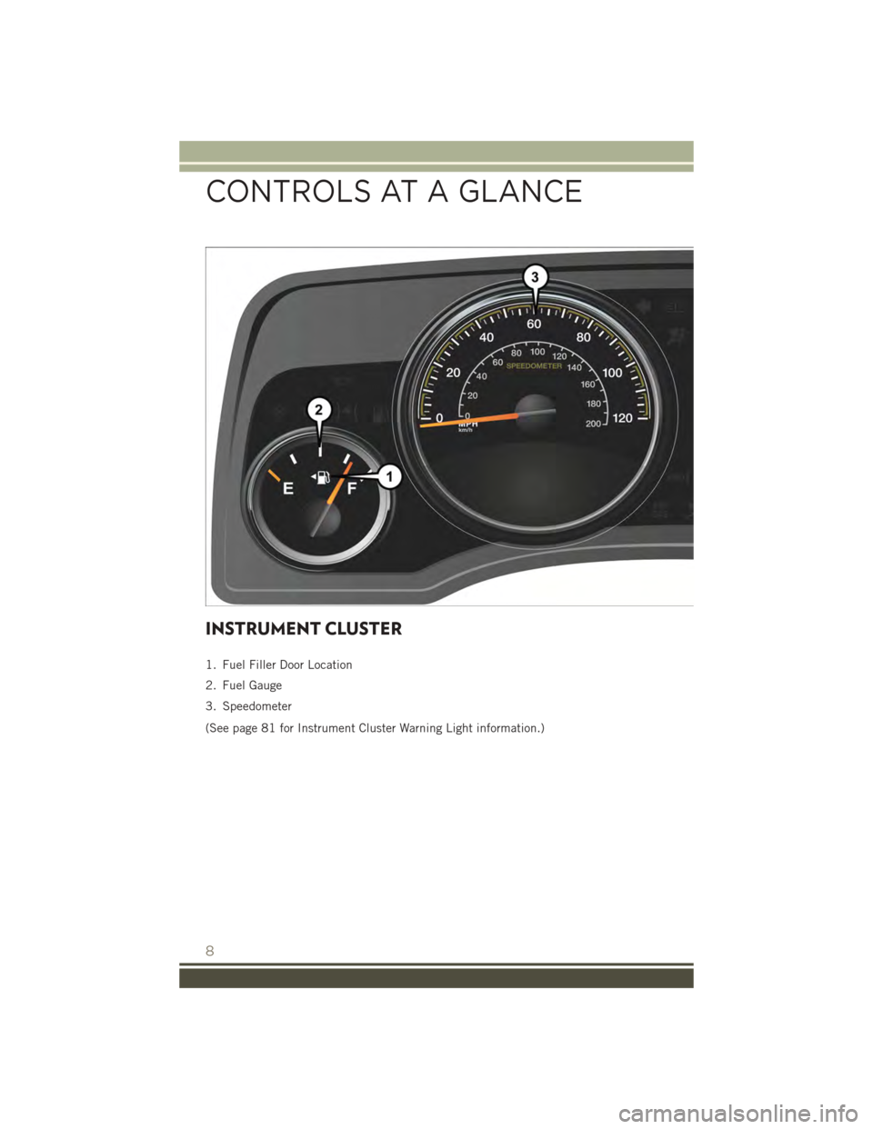
INSTRUMENT CLUSTER
1. Fuel Filler Door Location
2. Fuel Gauge
3. Speedometer
(See page 81 for Instrument Cluster Warning Light information.)
CONTROLS AT A GLANCE
8
Page 11 of 132

4. Tachometer
5. Engine Temperature Gauge
6. Gear Selection Display
(See page 86 for Instrument Cluster Indicator Light information.)
CONTROLS AT A GLANCE
9
Page 14 of 132

WARNING!
• Do not start or run an engine in a closed garage or confined area. Exhaust gas
contains Carbon Monoxide (CO) which is odorless and colorless. Carbon
Monoxide is poisonous and can cause serious injury or death when inhaled.
•Keep Key Fob transmitters away from children. Operation of the Remote Start
System, windows, door locks or other controls could cause serious injury or death.
VEHICLE SECURITY ALARM
The Vehicle Security Alarm monitors the vehicle doors for unauthorized entry and the
ENGINE START/STOP button for unauthorized operation. While the Vehicle Security
Alarm is armed, interior switches for door locks and decklid release are disabled. If
something triggers the alarm, the Vehicle Security Alarm will provide the following
audible and visible signals: the horn will pulse, the park lamps and/or turn signals
will flash, and the Vehicle Security Light in the instrument cluster will flash.
To A r m :
Lock the door using either the power door lock switch (one door must be open) or the
LOCK button on the Remote Keyless Entry (RKE) transmitter (doors can be open or
closed), and close all doors.
The Vehicle Security Light in the instrument cluster will flash for 16 seconds. This
shows that the Vehicle Security Alarm is arming. During this period, if a door is
opened, the ignition is cycled to ON/RUN, or the power door locks are unlocked in any
manner, the Vehicle Security Alarm will automatically disarm.
NOTE:
• The Vehicle Security Alarm will not arm if you lock the doors with the manual door
lock plungers.
• Once armed, the Vehicle Security Alarm disables the unlock switch on the driver
door trim panel and passenger door trim panel.
To D i s a r m T h e S y s t e m :
Push the Key Fob UNLOCK button or cycle the ignition to the ON/RUN position.
The Vehicle Security Alarm is designed to protect your vehicle. However, you can
create conditions where the Vehicle Security Alarm will give you a false alarm. If one
of the previously described arming sequences has occurred, the Vehicle Security
Alarm will arm regardless of whether you are in the vehicle or not. If you remain in the
vehicle and open a door, the alarm will sound. If this occurs, disarm the Vehicle
Security Alarm.
GETTING STARTED
12
Page 32 of 132

ELECTRONIC SPEED CONTROL
The Electronic Speed Control switches are located on the steering wheel.
Cruise ON/OFF
• Push the ON/OFF button to activate
the Speed Control.
NOTE:
CRUISEwill appear on the instru-
ment cluster to indicate the Speed Con-
trol is on.
• Push the ON/OFF button a second
time to turn the system off.
SET
With the Speed Control on, push and
release the SET – button to set a desired
speed.
Accel/Decel
To Increase Speed
• When the Electronic Speed Control is
set, you can increase speed by pushing
the RES+button.
The drivers preferred units can be selected through the instrument panel settings if
equipped. Refer to “ Understanding Your Instrument Panel” on the Owners Manual
DVD for more information. The speed increment shown is dependant on the chosen
speed unit of U.S. (mph) or Metric (km/h):
U.S. Speed (mph)
• Pushing the RES+button once will result in a 1 mph increase in set speed. Each
subsequent tap of the button results in an increase of 1 mph.
• If the button is continually pushed, the set speed will continue to increase until
the button is released, then the new set speed will be established.
Metric Speed (km/h)
• Pushing the RES+button once will result in a 1 km/h increase in set speed. Each
subsequent tap of the button results in an increase of 1 km/h.
• If the button is continually pushed, the set speed will continue to increase until
the button is released, then the new set speed will be established.
Electronic Speed Control Switches
1 — Push On/Off2 — Push Resume/Accel3 — Push Set/Decel4 — Push Cancel
OPERATING YOUR VEHICLE
30
Page 34 of 132

CONTINUOUSLY VARIABLE AUTOMATIC
TRANSMISSION (CVT)
While conventional automatic transmissions typically have 4, 5 or 6 speeds, the
Continuously Variable Transmission (CVT) has an infinite number of speeds. This allows
it to adjust to exactly the right ratio to optimize performance and fuel economy.
Under hard acceleration, you may hear more engine noise than with a conventional
transmission. The CVT may also occasionally feel like it is “shifting.” These
characteristics are perfectly normal and contribute to the CVT's efficiency.
SIX-SPEED AUTOMATIC TRANSMISSION
This electronically-controlled transmission provides a precise shift schedule. The
transmission electronics are self-calibrating; therefore, the first few shifts on a new
vehicle may be somewhat abrupt. This is a normal condition, and precision shifts will
develop within a few hundred miles (kilometers).
The transmission shift lever has only PARK, REVERSE, NEUTRAL, and DRIVE shift
positions. Manual shifts can be made using the Autostick®shift control. Moving the shift
lever to the left or right (-/+) while in the DRIVE position will manually select the
transmission gear, and will display the current gear in the instrument cluster as 6, 5, 4,
3, 2, 1.
Refer to your Owner’s Manual on the DVD for further information.
MANUAL CLIMATE CONTROLS
Manual Climate Controls
1 — Rotate Blower Control2 — Push Air Recirculation Button3 — Rotate Temperature Control
4 — Push A/C Button5 — Rotate Mode Control6 — Push Rear Window Defroster
OPERATING YOUR VEHICLE
32
Page 71 of 132

ELECTRONIC VEHICLE INFORMATION CENTER
(EVIC)
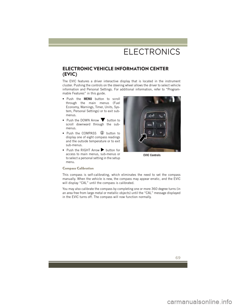
The EVIC features a driver interactive display that is located in the instrument
cluster. Pushing the controls on the steering wheel allows the driver to select vehicle
information and Personal Settings. For additional information, refer to “Program-
mable Features” in this guide.
• Push theMENUbutton to scroll
through the main menus (Fuel
Economy, Warnings, Timer, Units, Sys-
tem, Personal Settings) or to exit sub-
menus.
• Push the DOWN Arrowbutton to
scroll downward through the sub-
menus.
• Push the COMPASSbutton to
display one of eight compass readings
and the outside temperature or to exit
sub-menus.
• Push the RIGHT Arrowbutton for
access to main menus, sub-menus or
to select a personal setting in the setup
menu.
Compass Calibration
This compass is self-calibrating, which eliminates the need to set the compass
manually. When the vehicle is new, the compass may appear erratic, and the EVIC
will display “CAL” until the compass is calibrated.
You may also calibrate the compass by completing one or more 360 degree turns (in
an area free from large metal or metallic objects) until the “CAL” message displayed
in the EVIC turns off. The compass will now function normally.
EVIC Controls
ELECTRONICS
69