2015 JEEP GRAND CHEROKEE wiring
[x] Cancel search: wiringPage 80 of 636

Enhanced Accident Response System
In the event of an impact, if the communication network
remains intact, and the power remains intact, depending
on the nature of the event, the ORC will determine
whether to have the Enhanced Accident Response Sys-
tem perform the following functions:
•Cut off fuel to the engine.
•Flash hazard lights as long as the battery has power or
until the ignition is placed in the “OFF” position.
•Turn on the interior lights, which remain on as long as
the battery has power or until the ignition is placed in
the “OFF” position.
•Unlock the doors automatically.
System Reset Procedure
In order to reset the Enhanced Accident Response System
functions after an event, the ignition switch must be
changed from ignition START or ON/RUN to ignition
OFF.
Air Bag Warning Light
The air bags must be ready to inflate for your
protection in a collision. The Occupant Re-
straint Controller (ORC) monitors the internal
circuits and interconnecting wiring associated
with air bag system electrical components.
The ORC monitors the readiness of the electronic parts of
the air bag system whenever the ignition is in the START
or ON/RUN position. If the ignition is in the OFF
position or in the ACC position, the air bag system is not
on and the air bags will not inflate.
78 THINGS TO KNOW BEFORE STARTING YOUR VEHICLE
Page 82 of 636

WARNING!
Ignoring the Air Bag Warning Light in your instru-
ment panel could mean you won’t have the air bags
to protect you in a collision. If the light does not come
on as a bulb check when the ignition is first placed in
the on position, and stays on after you start the
vehicle, or if it comes on as you drive, have an
authorized dealer service the air bag system immedi-
ately.
Maintaining Your Air Bag System
WARNING!
•Modifications to any part of the air bag system
could cause it to fail when you need it. You could
be injured if the air bag system is not there to
(Continued)
WARNING!(Continued)
protect you. Do not modify the components or
wiring, including adding any kind of badges or
stickers to the steering wheel hub trim cover or the
upper right side of the instrument panel. Do not
modify the front bumper, vehicle body structure, or
add aftermarket side steps or running boards.
•It is dangerous to try to repair any part of the air
bag system yourself. Be sure to tell anyone who
works on your vehicle that it has an air bag system.
•Do not attempt to modify any part of your air bag
system. The air bag may inflate accidentally or may
not function properly if modifications are made.
Take your vehicle to an authorized dealer for any
air bag system service. If your seat, including your
trim cover and cushion, needs to be serviced in any
way (including removal or loosening/tightening of
(Continued)
80 THINGS TO KNOW BEFORE STARTING YOUR VEHICLE
Page 494 of 636

WARNING!(Continued)
•Total weight must be distributed between the tow
vehicle and the trailer such that the following four
ratings are not exceeded:
1. GVWR
2. GTW
3. GAWR
4. Tongue weight rating for the trailer hitch uti-
lized.
Towing Requirements — Trailer Lights And Wiring
Whenever you pull a trailer, regardless of the trailer size,
stoplights and turn signals on the trailer are required for
motoring safety.
The Trailer Tow Package may include a four- and seven-
pin wiring harness. Use a factory approved trailer har-
ness and connector.
NOTE:Do not cut or splice wiring into the vehicles
wiring harness.
The electrical connections are all complete to the vehicle
but you must mate the harness to a trailer connector.
Refer to the following illustrations.
492 STARTING AND OPERATING
Page 589 of 636

Front Turn Signal
1. Open the hood.
2. Turn the turn signal bulb one–quarter turn counter-
clockwise to remove from housing.
3. Disconnect the electrical connector and replace the
bulb.
CAUTION!
Do not touch the new bulb with your fingers. Oil
contamination will severely shorten bulb life. If the
bulb comes in contact with any oily surface, clean the
bulb with rubbing alcohol.
Front Fog Lamps
1. Reach through the cutout in the splash shield and
disconnect the wiring harness from the fog lamp
connector.2. Firmly grasp the bulb by the two latches and squeeze
them together to unlock the bulb from the back of the
front fog lamp housing.
3. Pull the bulb straight out from the keyed opening in
the housing.
CAUTION!
•Do not touch the new bulb with your fingers. Oil
contamination will severely shorten bulb life. If
the bulb comes in contact with any oily surface,
clean the bulb with rubbing alcohol.
•Always use the correct bulb size and type for
replacement. An incorrect bulb size or type may
overheat and cause damage to the lamp, the socket
or the lamp wiring.
7
MAINTAINING YOUR VEHICLE 587
Page 590 of 636

4. Align the index tabs of the front fog lamp bulb with
the slots in the collar of the bulb opening on the back
of the front fog lamp housing.
5. Insert the bulb into the housing until the index tabs are
engaged in the slots of the collar.
6. Firmly and evenly push the bulb straight into the lamp
housing until both tabs snap firmly into place and are
fully engaged.
7. Connect the wiring harness to the front fog lamp
connector.
Rear Tail, Stop, Turn Signal, And Backup Lamps
1. Raise the liftgate.
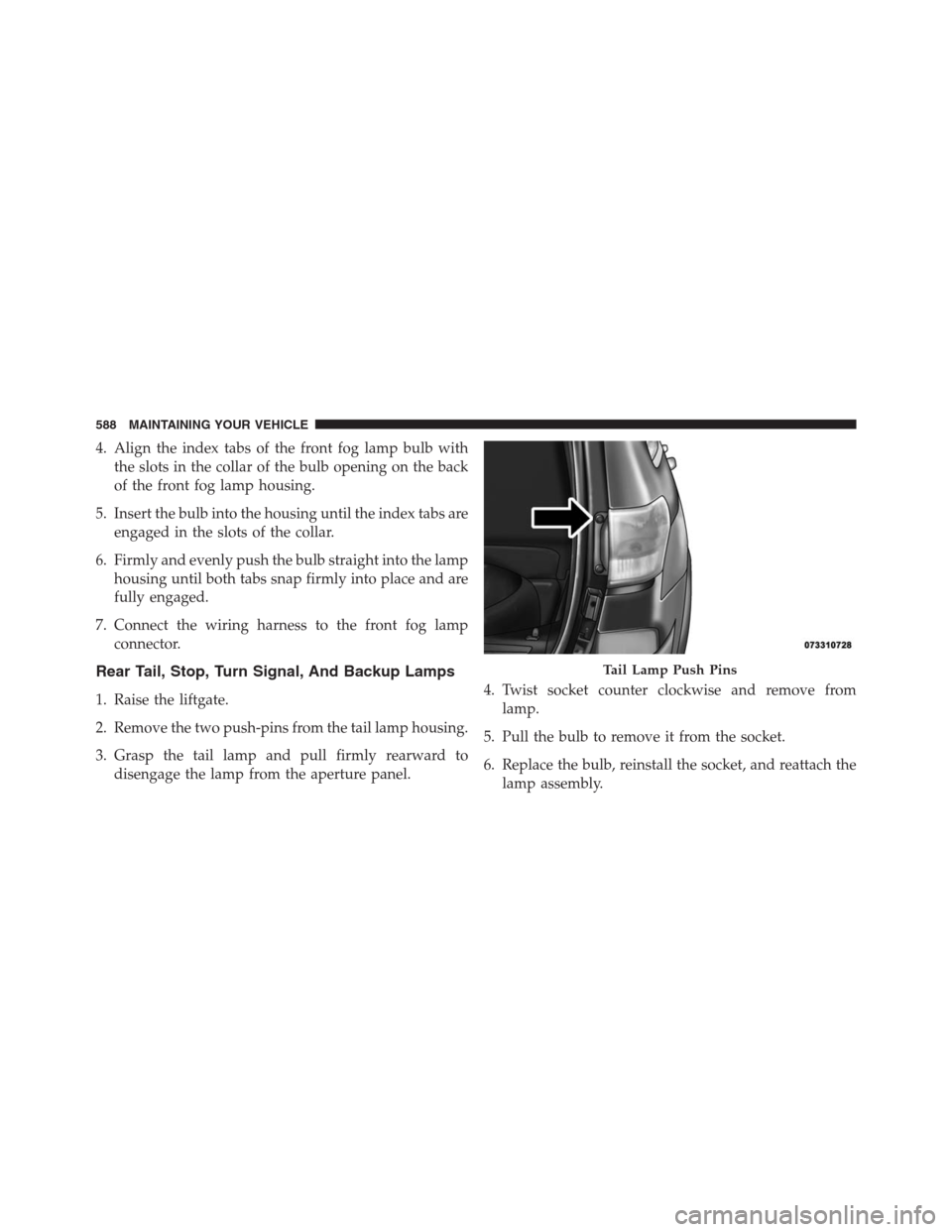
2. Remove the two push-pins from the tail lamp housing.
3. Grasp the tail lamp and pull firmly rearward to
disengage the lamp from the aperture panel.4. Twist socket counter clockwise and remove from
lamp.
5. Pull the bulb to remove it from the socket.
6. Replace the bulb, reinstall the socket, and reattach the
lamp assembly.
Tail Lamp Push Pins
588 MAINTAINING YOUR VEHICLE
Page 632 of 636

Tires.........................111,448, 454, 611
Aging (Life Of Tires).....................458
Air Pressure...........................448
Chains...............................460
Compact Spare.........................455
General Information..................448, 454
High Speed...........................451
Inflation Pressures.......................449
Life Of Tires...........................458
Load Capacity......................443, 444
Pressure Monitor System (TPMS)............463
Pressure Warning Light...................286
Quality Grading........................611
Radial...............................451
Replacement...........................458
Rotation..............................461
Safety............................436, 448
Sizes................................437
Snow Tires............................453Spare Tire......................454, 456, 505
Spinning.............................457
Tread Wear Indicators....................457
Tire Safety Information.....................436
Tongue Weight/Trailer Weight................489
Towing................................481
Behind A Motorhome....................497
Guide...............................486
Recreational...........................497
Weight...............................486
Towing Vehicle Behind A Motorhome...........497
Traction Control..........................426
Trailer Sway Control (TSC)..................435
Trailer Towing...........................481
Cooling System Tips.....................497
Hitches
..............................485
Minimum Requirements..................490
Trailer And Tongue Weight................489
Wiring...............................492
630 INDEX
Page 635 of 636

INSTALLATION OF RADIO TRANSMITTING
EQUIPMENTSpecial design considerations are incorporated into this
vehicle’s electronic system to provide immunity to radio
frequency signals. Mobile two-way radios and telephone
equipment must be installed properly by trained person-
nel. The following must be observed during installation.
The positive power connection should be made directly
to the battery and fused as close to the battery as possible.
The negative power connection should be made to body
sheet metal adjacent to the negative battery connection.
This connection should not be fused.
Antennas for two-way radios should be mounted on the
roof or the rear area of the vehicle. Care should be used
in mounting antennas with magnet bases. Magnets may
affect the accuracy or operation of the compass on
vehicles so equipped.The antenna cable should be as short as practical and
routed away from the vehicle wiring when possible. Use
only fully shielded coaxial cable.
Carefully match the antenna and cable to the radio to
ensure a low Standing Wave Ratio (SWR).
Mobile radio equipment with output power greater than
normal may require special precautions.
All installations should be checked for possible interfer-
ence between the communications equipment and the
vehicle’s electronic systems.