Page 251 of 636

3.Without releasing the buttonproceed with
“Canadian/Gate Operator Programming” step 2 and
follow all remaining steps.
Using HomeLink®
To operate, push and release the programmed
HomeLink® button. Activation will now occur for the
programmed device (i.e., garage door opener, gate opera-
tor, security system, entry door lock, home/office light-
ing, etc.,). The hand-held transmitter of the device may
also be used at any time.
Security
It is advised to erase all channels before you sell or turn
in your vehicle.
To do this, push and hold the two outside buttons for 20
seconds until the red indicator flashes. Note that all
channels will be erased. Individual channels cannot be
erased.The HomeLink® Universal Transceiver is disabled when
the Vehicle Security Alarm is active.
Troubleshooting Tips
If you are having trouble programming HomeLink®,
here are some of the most common solutions:
•Replace the battery in the original hand-held transmit-
ter.
•Push the LEARN button on the Garage Door Opener
to complete the training for a Rolling Code.
•Did you unplug the device for programming and
remember to plug it back in?
If you have any problems, or require assistance, please
call toll-free 1-800-355-3515 or, on the Internet at
HomeLink.com for information or assistance.3
UNDERSTANDING THE FEATURES OF YOUR VEHICLE 249
Page 253 of 636
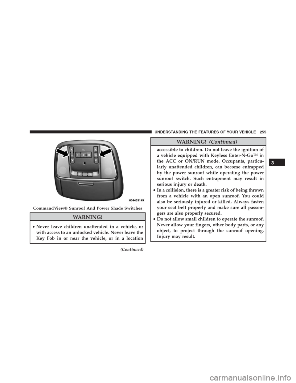
POWER SUNROOF — IF EQUIPPED
The power sunroof switch is located between the sun
visors on the overhead console.
WARNING!
•Never leave children unattended in a vehicle, or
with access to an unlocked vehicle. Never leave the
Key Fob in or near the vehicle, or in a location
accessible to children. Do not leave the ignition of
a vehicle equipped with Keyless Enter-N-Go™ in
the ACC or ON/RUN mode. Occupants, particu-
larly unattended children, can become entrapped
by the power sunroof while operating the power
sunroof switch. Such entrapment may result in
serious injury or death.
•In a collision, there is a greater risk of being thrown
from a vehicle with an open sunroof. You could
also be seriously injured or killed. Always fasten
your seat belt properly and make sure all passen-
gers are also properly secured.
(Continued)
Power Sunroof Switch
3
UNDERSTANDING THE FEATURES OF YOUR VEHICLE 251
Page 257 of 636

WARNING!
•Never leave children unattended in a vehicle, or
with access to an unlocked vehicle. Never leave the
Key Fob in or near the vehicle, or in a location
(Continued)
WARNING!(Continued)
accessible to children. Do not leave the ignition of
a vehicle equipped with Keyless Enter-N-Go™ in
the ACC or ON/RUN mode. Occupants, particu-
larly unattended children, can become entrapped
by the power sunroof while operating the power
sunroof switch. Such entrapment may result in
serious injury or death.
•In a collision, there is a greater risk of being thrown
from a vehicle with an open sunroof. You could
also be seriously injured or killed. Always fasten
your seat belt properly and make sure all passen-
gers are also properly secured.
•Do not allow small children to operate the sunroof.
Never allow your fingers, other body parts, or any
object, to project through the sunroof opening.
Injury may result.
CommandView® Sunroof And Power Shade Switches
3
UNDERSTANDING THE FEATURES OF YOUR VEHICLE 255
Page 280 of 636

CAUTION!(Continued)
•Do not use scrapers, sharp instruments, or abrasive
window cleaners on the interior surface of the
window.
•Keep all objects a safe distance from the window.
ROOF LUGGAGE RACK — IF EQUIPPED
The crossbars and siderails are designed to carry the
weight on vehicles equipped with a luggage rack. The
load must not exceed 150 lbs (68 kg), and should be
uniformly distributed over the luggage rack crossbars.
NOTE:If not equipped with crossbars, your authorized
dealer can order and install MOPAR® crossbars built
specifically for this roof rack system.
Distribute cargo weight evenly on the roof rack crossbars.
The roof rack does not increase the total load carrying
capacity of the vehicle. Be sure the total load of cargoinside the vehicle plus that on the external rack does not
exceed the maximum vehicle load capacity.
To move the crossbars, loosen the attachments, located at
the upper edge of each crossbar, approximately eight
turns using the anti-theft wrench provided with the
MOPAR® crossbars. Then, move the crossbar to the
desired position, keeping the crossbars parallel to the
rack frame. Once the crossbar is in the desired position,
retighten the with the wrench to lock the crossbar into
position.
NOTE:
•To help control wind noise when the crossbars are not
in use, place the front and rear crossbars approxi-
mately 24 in (61 cm) apart. Optimal noise reduction
can then be achieved by adjusting the front crossbar
forward or aft using increments of 1 in (2.5 cm).
278 UNDERSTANDING THE FEATURES OF YOUR VEHICLE
Page 288 of 636

INSTRUMENT CLUSTER DESCRIPTIONS
1. Tachometer
Indicates the engine speed in revolutions per minute
(RPM x 1000).
2. Seat Belt Reminder Light
When the ignition switch is first turned to the
ON/RUN position, this light will turn on for four
to eight seconds as a bulb check. During the bulb
check, if the driver’s seat belt is unbuckled, a chime will
sound. After the bulb check or when driving, if the driver
or front passenger seat belt remains unbuckled, the Seat
Belt Indicator Light will flash or remain on continuously.
Refer to “Occupant Restraints” in “Things To Know
Before Starting Your Vehicle” for further information.3. Anti-Lock Brake (ABS) Light
This light monitors the Anti-Lock Brake System
(ABS). The light will turn on when the ignition
switch is turned to the ON/RUN position and
may stay on for as long as four seconds.
If the ABS light remains on or turns on while driving, it
indicates that the Anti-Lock portion of the brake system
is not functioning and that service is required. However,
the conventional brake system will continue to operate
normally if the BRAKE warning light is not on.
If the ABS light is on, the brake system should be serviced
as soon as possible to restore the benefits of Anti-Lock
brakes. If the ABS light does not turn on when the
ignition switch is turned to the ON/RUN position, have
the light inspected by an authorized dealer.
4. High Beam Indicator
Indicates that headlights are on high beam.
286 UNDERSTANDING YOUR INSTRUMENT PANEL
Page 291 of 636

CAUTION!
Driving with a hot engine cooling system could
damage your vehicle. If the temperature gauge reads
“H” pull over and stop the vehicle. Idle the vehicle
with the air conditioner turned off until the pointer
drops back into the normal range. If the pointer
remains on the “H” and you hear continuous chimes,
turn the engine off immediately and call an autho-
rized dealer for service.
WARNING!
A hot engine cooling system is dangerous. You or
others could be badly burned by steam or boiling
coolant. You may want to call an authorized dealer
for service if your vehicle overheats. If you decide to
look under the hood yourself, see “Maintaining Your
(Continued)
WARNING!(Continued)
Vehicle”. Follow the warnings under the Cooling
System Pressure Cap paragraph.
12. Brake Warning Light
This light monitors various brake functions,
including brake fluid level and parking brake
application. If the brake light turns on it may
indicate that the parking brake is applied, that
the brake fluid level is low, or that there is a problem with
the anti-lock brake system reservoir.
If the light remains on when the parking brake has been
disengaged, and the fluid level is at the full mark on the
master cylinder reservoir, it indicates a possible brake
hydraulic system malfunction or that a problem with the
Brake Booster has been detected by the Anti-Lock Brake
System (ABS) / Electronic Stability Control (ESC) system.
In this case, the light will remain on until the condition
4
UNDERSTANDING YOUR INSTRUMENT PANEL 289
Page 292 of 636

has been corrected. If the problem is related to the brake
booster, the ABS pump will run when applying the brake
and a brake pedal pulsation may be felt during each stop.
The dual brake system provides a reserve braking capac-
ity in the event of a failure to a portion of the hydraulic
system. A leak in either half of the dual brake system is
indicated by the Brake Warning Light, which will turn on
when the brake fluid level in the master cylinder has
dropped below a specified level.
The light will remain on until the cause is corrected.
NOTE:The light may flash momentarily during sharp
cornering maneuvers, which change fluid level condi-
tions. The vehicle should have service performed, and
the brake fluid level checked.
If brake failure is indicated, immediate repair is neces-
sary.WARNING!
Driving a vehicle with the red brake light on is
dangerous. Part of the brake system may have failed.
It will take longer to stop the vehicle. You could have
a collision. Have the vehicle checked immediately.
Vehicles equipped with the Anti-Lock Brake System
(ABS), are also equipped with Electronic Brake Force
Distribution (EBD). In the event of an EBD failure, the
Brake Warning Light will turn on along with the ABS
Light. Immediate repair to the ABS system is required.
Operation of the Brake Warning Light can be checked by
turning the ignition switch from the OFF position to the
ON/RUN position. The light should illuminate for ap-
proximately two seconds. The light should then turn off
unless the parking brake is applied or a brake fault is
detected. If the light does not illuminate, have the light
inspected by an authorized dealer.
290 UNDERSTANDING YOUR INSTRUMENT PANEL
Page 301 of 636

seconds and then returns to the previous screen. An
example of this message type is “Automatic High Beams
On.”
Engine Oil Life Reset
Oil Change Required
Your vehicle is equipped with an engine oil change
indicator system. The “Oil Change Required” message
will display in the DID for five seconds after a single
chime has sounded, to indicate the next scheduled oil
change interval. The engine oil change indicator system
is duty cycle based, which means the engine oil change
interval may fluctuate, dependent upon your personal
driving style.
Unless reset, this message will continue to display each
time you cycle the ignition to the ON/RUN position. To
turn off the message temporarily, push and release theOK button. To reset the oil change indicator system (after
performing the scheduled maintenance), refer to the
following procedure.
Oil Change Reset Procedure
1. Without pushing the brake pedal, push and release the
ENGINE START/STOP button and place the ignition
to the ON/RUN position (do not start the engine).
2. Fully push the accelerator pedal, slowly, three times
within 10 seconds.
3. Without pushing the brake pedal, push and release the
ENGINE START/STOP button once to return the
ignition to the OFF/LOCK position.
NOTE:If the indicator message illuminates when you
start the vehicle, the oil change indicator system did not
reset. If necessary, repeat this procedure.4
UNDERSTANDING YOUR INSTRUMENT PANEL 299