Page 295 of 636

U.S. Federal regulations require that upon transfer of
vehicle ownership, the seller certify to the purchaser the
correct mileage that the vehicle has been driven. If your
odometer needs to be repaired or serviced, the repair
technician should leave the odometer reading the same
as it was before the repair or service. If she/he cannot do
so, then the odometer must be set at zero, and a sticker
must be placed in the door jamb stating what the mileage
was before the repair or service. It is a good idea for you
to make a record of the odometer reading before the
repair/service, so that you can be sure that it is properly
reset, or that the door jamb sticker is accurate if the
odometer must be reset at zero.
When the appropriate conditions exist, this Driver Infor-
mation Display (DID) messages. Refer to “Driver Infor-
mation Display” in this section.16. Selectable DID Menu
This area of the cluster will display the DID selectable
menu. For further information, refer to “Driver Informa-
tion Display (DID)” in this section.
17. Air Bag Warning Light
This light will turn on for four to eight seconds
as a bulb check when the ignition switch is first
turned to the ON/RUN position. If the light is
either not on during starting, stays on, or turns
on while driving, have the system inspected at an autho-
rized dealer as soon as possible. Refer to “Occupant
Restraints” in “Things To Know Before Starting Your
Vehicle” for further information.
18. Vehicle Security Light
This light will flash rapidly for approximately
15 seconds when the vehicle security alarm is
arming. The light will flash at a slower speed
4
UNDERSTANDING YOUR INSTRUMENT PANEL 293
Page 296 of 636

continuously after the alarm is set. The security light will
also come on for about three seconds when the ignition is
first turned on.
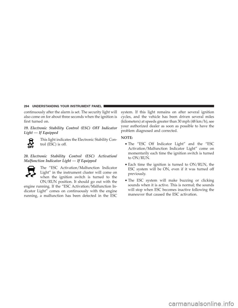
19. Electronic Stability Control (ESC) OFF Indicator
Light — If Equipped
This light indicates the Electronic Stability Con-
trol (ESC) is off.
20. Electronic Stability Control (ESC) Activation/
Malfunction Indicator Light — If Equipped
The “ESC Activation/Malfunction Indicator
Light” in the instrument cluster will come on
when the ignition switch is turned to the
ON/RUN position. It should go out with the
engine running. If the “ESC Activation/Malfunction In-
dicator Light” comes on continuously with the engine
running, a malfunction has been detected in the ESCsystem. If this light remains on after several ignition
cycles, and the vehicle has been driven several miles
(kilometers) at speeds greater than 30 mph (48 km/h), see
your authorized dealer as soon as possible to have the
problem diagnosed and corrected.
NOTE:
•The “ESC Off Indicator Light” and the “ESC
Activation/Malfunction Indicator Light” come on
momentarily each time the ignition switch is turned
to ON/RUN.
•Each time the ignition is turned to ON/RUN, the
ESC system will be ON, even if it was turned off
previously.
•The ESC system will make buzzing or clicking
sounds when it is active. This is normal; the sounds
will stop when ESC becomes inactive following the
maneuver that caused the ESC activation.
294 UNDERSTANDING YOUR INSTRUMENT PANEL
Page 297 of 636
21. Park/Headlight ON Indicator — If Equipped
This indicator will illuminate when the park
lights or headlights are turned on.
DRIVER INFORMATION DISPLAY (DID)
The Driver Information Display (DID) features a driver-
interactive display that is located in the instrument
cluster.
The DID Menu items consists of the following:
•Speedometer Main Gauge
•MPH <-> KM/H
•Vehicle Info
Driver Information Display (DID) Location
4
UNDERSTANDING YOUR INSTRUMENT PANEL 295
Page 299 of 636

•DOWN Arrow Button
Push and release the DOWN arrow button to
scroll downward through the main menu and
submenus.
•RIGHT Arrow Button
Push and release the RIGHT arrow button to
access the information screens or submenu
screens of a main menu item.
•BACK Arrow Button
Push the LEFT arrow button to return to the
main menu from an info screen or submenu
item.
•OK Button
The OK button may be used for the following:
SelectionReset (hold)
Clearing (hold)
DID Displays
The DID displays are located in the center portion of the
cluster and consist of multiple sections:
1. Main Screen — The inner ring of the display will
illuminate in grey under normal conditions, yellow for
non critical warnings, red for critical warnings, and
white for on demand information.
2. Audio Information and Sub-menu Information —
Whenever there are submenus available, the position
within the submenus is shown here.
3. Reconfigurable Telltales/Information
4. Telltales/Indicators
5. Gear Selector Status (PRNDL)
4
UNDERSTANDING YOUR INSTRUMENT PANEL 297
Page 313 of 636

•The time will continue to display until the OK button
is pushed to reset or the vehicle is brought to a stop.
NOTE:LAST and BEST timer data can be seen on the
Uconnect® Performance Pages App.
Braking Distance
When selected, this screen displays the vehicle’s braking
distance and the speed at which the brake pedal was
depressed.
•This feature will only function when applying the
brakes at speeds above 30 mph (48 km/h).
•Engaging the parking brake will disable this feature.
•The word “READY” will display when conditions are
met for the event to begin.
•The distance and speed measurements display while
the event is taking place.•The distance measurement will be aborted if the brake
pedal is released before the vehicle comes to a com-
plete stop.
•The distance and speed measurements will continue to
display until the conditions are met for another event
to be recorded.
•Pushing the OK button will clear the current run and
prepare the cluster to record a new run.
1/8 Mile, 1/4 Mile
When selected, this screen displays the time it takes the
vehicle to travel 1/8 mile within 15 seconds, (1/4 mile)
within 25 seconds.
•The feature will “ready” when the vehicle is at 0 mph
(0 km/h). The word “READY” will display when
conditions are met for the event to begin.
4
UNDERSTANDING YOUR INSTRUMENT PANEL 311
Page 316 of 636
OK button to enter the submenus and follow the prompts
on the screen as needed. The Screen Setup feature allows
you to change what information is displayed in the
instrument cluster as well as the location that information
is displayed.
Screen Setup Driver Selectable Items
Current Gear
•On
•Off
Upper Left
•None
•Compass
•Outside Temp (default setting)
•Time•Range To Empty (RTE)
•Fuel Economy Average
•Fuel Economy Current
•Trip A
•Trip B
Upper Right
•None
•Compass (default setting)
•Outside Temp
•Time
•Range To Empty (RTE)
•Fuel Economy Average
•Fuel Economy Current
314 UNDERSTANDING YOUR INSTRUMENT PANEL
Page 322 of 636

that setting has been selected. Press the back arrow
button on the touchscreen to return to the previous
menu.
•Navigation Turn-By-Turn Displayed In Cluster — If
Equipped
When this feature is selected, To make your selection,
press the “Navigation Turn-By-Turn Displayed In Clus-
ter” button on the touchscreen, until a check-mark ap-
pears next to the setting, showing that setting has been
selected. Press the back arrow button on the touchscreen
to return to the previous menu.
Voice
After pressing the “Voice” button on the touchscreen the
following settings will be available:
•Voice Response Length
When in this display, you may change the Voice Re-
sponse Length settings. To change the Voice ResponseLength, press the “Brief” or “Detailed” button on the
touchscreen until a check-mark appears next to the
setting, showing that setting has been selected. Press the
back arrow button on the touchscreen to return to the
previous menu.
•Show Command List
When in this display, you may choose to Always, With
Help, or Never display the Teleprompter with possible
options while in a voice session. To change the Show
Command List settings, press the “Always,” “With
Help,” or “Never” button on the touchscreen until a
check-mark appears next to the setting, showing that
setting has been selected. Press the back arrow button on
the touchscreen to return to the previous menu.
320 UNDERSTANDING YOUR INSTRUMENT PANEL
Page 410 of 636
toggle between SPORT mode and DRIVE mode. You do
not need to press the shift lever button when toggling
between DRIVE and SPORT modes. Manual shifts can be
made using the shift paddles mounted on the steering
wheel. Pressing the shift paddles (-/+) while in the
DRIVE or SPORT position will manually select the trans-
mission gear, and will display the current gear in the
instrument cluster. Refer to�Paddle Shift Mode�in this
section for further information.
Shift Lever
408 STARTING AND OPERATING