Page 266 of 717
sunroof will automatically retract. Remove the obstruc-
tion if this occurs. Next, press the switch forward and
release to Express Close.
NOTE:If three consecutive sunroof close attempts result
in Pinch Protect reversals, the fourth close attempt will be
a Manual Close movement with Pinch Protect disabled.
Wind Buffeting
Wind buffeting can be described as the perception of
pressure on the ears or a helicopter-type sound in the
ears. Your vehicle may exhibit wind buffeting with the
windows down, or the sunroof (if equipped) in certain
open or partially open positions. This is a normal occur-
rence and can be minimized. If the buffeting occurs with
the rear windows open, open the front and rear windows
together to minimize the buffeting. If the buffeting occurs
with the sunroof open, adjust the sunroof opening to
minimize the buffeting or open any window.
Sunroof Maintenance
Use only a non-abrasive cleaner and a soft cloth to clean
the glass panel.
Ignition Off Operation
NOTE:
•The power sunroof switch can remain active for up to
approximately ten minutes after the vehicles ignition is
cycled to the Off position. Opening either front door
will cancel this feature.
•This feature is programmable using the Uconnect®
System. Refer to “Uconnect® Settings” in “Under-
standing Your Instrument Panel” for further informa-
tion.
Sunroof Fully Closed
Press the switch forward and release to ensure that the
sunroof is fully closed.
264 UNDERSTANDING THE FEATURES OF YOUR VEHICLE
Page 267 of 717
ELECTRICAL POWER OUTLETS
Your vehicle is equipped with 12 Volt (13 Amp) power
outlets that can be used to power cellular phones, small
electronics and other low powered electrical accessories.
The power outlets are labeled with either a “key” or a
“battery” symbol to indicate how the outlet is powered.
Power outlets labeled with a “key” are powered when
the ignition is in the ON or ACC position, while the
outlets labeled with a “battery” are connected directly to
the battery and powered at all times.
NOTE:
•All accessories connected to the “battery” powered
outlets should be removed or turned off when the
vehicle is not in use to protect the battery against
discharge.
•To ensure proper cigar lighter operation, a MOPAR®
knob and element must be used.
CAUTION!
Power outlets are designed for accessory plugs only.
Do not insert any other object in the power outlets as
this will damage the outlet and blow the fuse.
Improper use of the power outlet can cause damage
not covered by your New Vehicle Limited Warranty.
3
UNDERSTANDING THE FEATURES OF YOUR VEHICLE 265
Page 269 of 717
The rear power outlet is located in the right rear cargo
area.
NOTE:The rear power outlet can be switched from
switched “ignition” only to constant “battery” powered
all the time. See your local authorized dealer for details.
Rear Power Outlet
Power Outlet Right Rear Quarter Panel Fuse
3
UNDERSTANDING THE FEATURES OF YOUR VEHICLE 267
Page 285 of 717
release of the switch, the wipers will resume the continu-
ous rear wiper operation. When this rotary control is in
the OFF position, rotating it downward will activate the
rear washer pump which will continue to operate as long
as the switch is held. Once the switch is released it will
return to the OFF position and the wipers will cycle
several times before returning to the parked position.
NOTE:As a protective measure, the pump will stop if the
switch is held for more than 20 seconds. Once the switch
is released the pump will resume normal operation.
If the rear wiper is operating when the ignition is turned
OFF, the wiper will automatically return to the “park”
position.
Rear Window Defroster
The rear window defroster button is located on
the climate control panel. Press this button to turn
on the rear window defroster and the heated outside
mirrors (if equipped). An indicator in the button will
illuminate when the rear window defroster is on. The
rear window defroster automatically turns off after ap-
proximately 10 minutes. For an additional five minutes of
operation, press the button a second time.
NOTE:To prevent excessive battery drain, use the rear
window defroster only when the engine is operating.
CAUTION!
Failure to follow these cautions can cause damage to
the heating elements:
•Use care when washing the inside of the rear
window. Do not use abrasive window cleaners on
the interior surface of the window. Use a soft cloth
and a mild washing solution, wiping parallel to the
heating elements. Labels can be peeled off after
soaking with warm water.
(Continued)
3
UNDERSTANDING THE FEATURES OF YOUR VEHICLE 283
Page 292 of 717
INSTRUMENT PANEL FEATURES
1 — Air Outlet6 — Lower Switch Bank11 — Hood Release2 — Instrument Cluster7 — Hazard Switch12 — Fuel Door Release3—Radio8—StorageBin(SDCard,AUX,USBMediaHub) 13—HeadlightSwitch4—GloveCompartment9—ESCButton14 — Dimmer Control5 — Climate Controls10 — Ignition Switch
290 UNDERSTANDING YOUR INSTRUMENT PANEL
Page 294 of 717

INSTRUMENT CLUSTER DESCRIPTIONS
1. Tachometer
Indicates the engine speed in revolutions per minute
(RPM x 1000).
2. Seat Belt Reminder Light
When the ignition switch is first turned to the
ON/RUN position, this light will turn on for four
to eight seconds as a bulb check. During the bulb
check, if the driver’s seat belt is unbuckled, a chime will
sound. After the bulb check or when driving, if the driver
or front passenger seat belt remains unbuckled, the Seat
Belt Indicator Light will flash or remain on continuously.
Refer to “Occupant Restraints” in “Things To Know
Before Starting Your Vehicle” for further information.
3. Anti-Lock Brake (ABS) Light
This light monitors the Anti-Lock Brake System
(ABS). The light will turn on when the ignition
switch is turned to the ON/RUN position and
may stay on for as long as four seconds.
If the ABS light remains on or turns on while driving, it
indicates that the Anti-Lock portion of the brake system
is not functioning and that service is required. However,
the conventional brake system will continue to operate
normally if the BRAKE warning light is not on.
If the ABS light is on, the brake system should be serviced
as soon as possible to restore the benefits of Anti-Lock
brakes. If the ABS light does not turn on when the
ignition switch is turned to the ON/RUN position, have
the light inspected by an authorized dealer.
4. High Beam Indicator
Indicates that headlights are on high beam.
292 UNDERSTANDING YOUR INSTRUMENT PANEL
Page 298 of 717
has been corrected. If the problem is related to the brake
booster, the ABS pump will run when applying the brake
and a brake pedal pulsation may be felt during each stop.
The dual brake system provides a reserve braking capac-
ity in the event of a failure to a portion of the hydraulic
system. A leak in either half of the dual brake system is
indicated by the Brake Warning Light, which will turn on
when the brake fluid level in the master cylinder has
dropped below a specified level.
The light will remain on until the cause is corrected.
NOTE:The light may flash momentarily during sharp
cornering maneuvers, which change fluid level condi-
tions. The vehicle should have service performed, and
the brake fluid level checked.
If brake failure is indicated, immediate repair is neces-
sary.
WARNING!
Driving a vehicle with the red brake light on is
dangerous. Part of the brake system may have failed.
It will take longer to stop the vehicle. You could have
a collision. Have the vehicle checked immediately.
Vehicles equipped with the Anti-Lock Brake System
(ABS), are also equipped with Electronic Brake Force
Distribution (EBD). In the event of an EBD failure, the
Brake Warning Light will turn on along with the ABS
Light. Immediate repair to the ABS system is required.
Operation of the Brake Warning Light can be checked by
turning the ignition switch from the OFF position to the
ON/RUN position. The light should illuminate for ap-
proximately two seconds. The light should then turn off
unless the parking brake is applied or a brake fault is
detected. If the light does not illuminate, have the light
inspected by an authorized dealer.
296 UNDERSTANDING YOUR INSTRUMENT PANEL
Page 299 of 717
The light also will turn on when the parking brake is
applied with the ignition switch in the ON/RUN posi-
tion.
NOTE:This light shows only that the parking brake is
applied. It does not show the degree of brake application.
13. Fuel Gauge/Fuel Door Reminder
The fuel pump symbol points to the side of the vehicle
where the fuel door is located. The pointer shows the
level of fuel in the fuel tank when the ignition switch is in
the ON/RUN position.
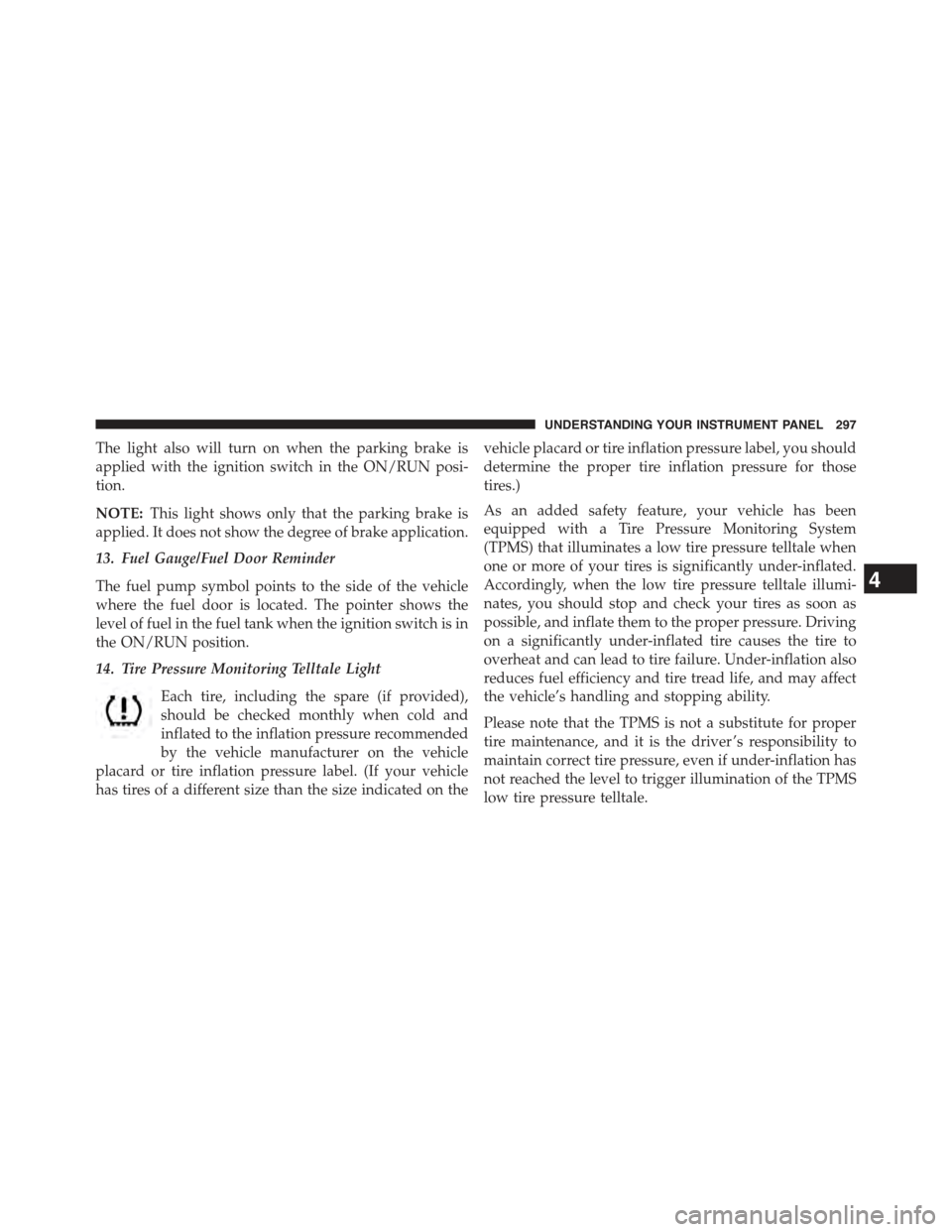
14. Tire Pressure Monitoring Telltale Light
Each tire, including the spare (if provided),
should be checked monthly when cold and
inflated to the inflation pressure recommended
by the vehicle manufacturer on the vehicle
placard or tire inflation pressure label. (If your vehicle
has tires of a different size than the size indicated on the
vehicle placard or tire inflation pressure label, you should
determine the proper tire inflation pressure for those
tires.)
As an added safety feature, your vehicle has been
equipped with a Tire Pressure Monitoring System
(TPMS) that illuminates a low tire pressure telltale when
one or more of your tires is significantly under-inflated.
Accordingly, when the low tire pressure telltale illumi-
nates, you should stop and check your tires as soon as
possible, and inflate them to the proper pressure. Driving
on a significantly under-inflated tire causes the tire to
overheat and can lead to tire failure. Under-inflation also
reduces fuel efficiency and tire tread life, and may affect
the vehicle’s handling and stopping ability.
Please note that the TPMS is not a substitute for proper
tire maintenance, and it is the driver ’s responsibility to
maintain correct tire pressure, even if under-inflation has
not reached the level to trigger illumination of the TPMS
low tire pressure telltale.
4
UNDERSTANDING YOUR INSTRUMENT PANEL 297