Page 185 of 717
from the windshield washers of the vehicle ahead. Rotate
the end of the multifunction lever to one of four settings
to activate this feature.
The sensitivity of the system can be adjusted with the
multifunction lever. Wiper delay position one is the least
sensitive, and wiper delay position four is the most
sensitive. Setting three should be used for normal rain
conditions. Settings one and two can be used if the driver
desires less wiper sensitivity. Setting four can be used if
the driver desires more sensitivity. Place the wiper switch
in the OFF position when not using the system.
NOTE:
•The Rain Sensing feature will not operate when the
wiper switch is in the low or high-speed position.
•The Rain Sensing feature may not function properly
when ice, or dried salt water is present on the wind-
shield.
•Use of Rain-X® or products containing wax or silicone
may reduce Rain Sensing performance.
•The Rain Sensing feature can be turned on and off
using the Uconnect® System, refer to “Uconnect®
Settings” in “Understanding Your Instrument Panel”
for further information.
The Rain Sensing system has protection features for the
wiper blades and arms, and will not operate under the
following conditions:
•Low Ambient Temperature— When the ignition is
first turned ON, the Rain Sensing system will not
operate until the wiper switch is moved, vehicle speed
is greater than 0 mph (0 km/h), or the outside tem-
perature is greater than 32°F (0°C).
•Transmission In NEUTRAL Position— When the
ignition is ON, and the automatic transmission is in
the NEUTRAL position, the Rain Sensing system will
3
UNDERSTANDING THE FEATURES OF YOUR VEHICLE 183
Page 189 of 717
NOTE:The engine must be running for the heated
steering wheel to operate.
Vehicles Equipped With Remote Start
On models that are equipped with remote start, the
heated steering wheel can be programmed to come on
during a remote start through the Uconnect® system.
Refer to “Uconnect® Settings” in “Understanding Your
Instrument Panel” for further information.
WARNING!
•Persons who are unable to feel pain to the skin
because of advanced age, chronic illness, diabetes,
spinal cord injury, medication, alcohol use, exhaus-
tion, or other physical conditions must exercise
care when using the steering wheel heater. It may
cause burns even at low temperatures, especially if
used for long periods.
•Do not place anything on the steering wheel that
insulates against heat, such as a blanket or steering
wheel covers of any type and material. This may
cause the steering wheel heater to overheat.
3
UNDERSTANDING THE FEATURES OF YOUR VEHICLE 187
Page 209 of 717
WARNING!
When the ACC system is resumed, the driver must
ensure that there are no pedestrians, vehicles or
objects in the path of the vehicle. Failure to follow
these warnings can result in a collision and death or
serious personal injury.
Adaptive Cruise Control (ACC) Menu
The DID displays the current ACC system settings. The
DID is located in the center of the instrument cluster. The
information it displays depends on ACC system status.
Press the ADAPTIVE CRUISE CONTROL (ACC) ON/
OFF button (located on the steering wheel) until one of
the following displays in the DID:
Adaptive Cruise Control Off
When ACC is deactivated, the display will read “Adap-
tive Cruise Control Off.”
Adaptive Cruise Control Ready
When ACC is activated but the vehicle speed setting has
not been selected, the display will read “Adaptive Cruise
Control Ready.”
Press the SET + or the SET- button (located on the
steering wheel) and the following will display in the DID:
ACC SET
When ACC is set, the set speed will display in the
instrument cluster.
The ACC screen may display once again if any ACC
activity occurs, which may include any of the following:
•Distance Setting Change
•System Cancel
•Driver Override
•System Off
3
UNDERSTANDING THE FEATURES OF YOUR VEHICLE 207
Page 224 of 717
Changing FCW And Active Braking Status
The FCW Sensitivity And Active Braking Settings are
programmable through the Uconnect® System. Refer to
“Uconnect® Settings” in “Understanding Your Instru-
ment Panel” for further information.
The default status of FCW is the “Far” setting and the
Active Braking is the “On” setting, this allows the system
to warn you of a possible collision with the vehicle in
front of you when you are farther away and it applies
limited braking. This gives you the most reaction time to
avoid a possible collision.
Changing the FCW status to the “Near” setting, allows
the system to warn you of a possible collision with the
vehicle in front of you when you are much closer. This
setting provides less reaction time than the “Far” setting,
which allows for a more dynamic driving experience.
NOTE:
•The system will retain the last setting selected by the
driver after ignition shut down.
•FCW may not react to irrelevant objects such as
overhead objects, ground reflections, objects not in the
path of the car, stationary objects that are far away,
oncoming traffic, or leading vehicles with the same or
higher rate of speed.
•FCW will be disabled like ACC, with the unavailable
screens.
222 UNDERSTANDING THE FEATURES OF YOUR VEHICLE
Page 226 of 717

active until the vehicle speed is increased to approxi-
mately 7 mph (11 km/h) or above. When in REVERSE
and above the system’s operating speed, a warning will
appear within the Driver Information Display (DID)
indicating the vehicle speed is too fast. The system will
become active again if the vehicle speed is decreased to
speeds less than approximately 6 mph (9 km/h).
ParkSense® Sensors
The four ParkSense® sensors, located in the rear fascia/
bumper, monitor the area behind the vehicle that is
within the sensors’ field of view. The sensors can detect
obstacles from approximately 12 in (30 cm) up to 79 in
(200 cm) from the rear fascia/bumper in the horizontal
direction, depending on the location, type and orienta-
tion of the obstacle.
ParkSense® Warning Display
The ParkSense® Warning screen will only be displayed if
Sound and Display is selected from the Customer -
Programmable Features section of the Uconnect® Sys-
tem. Refer to#Uconnect® Settings” in “Understanding
Your Instrument Panel” for further information.
The ParkSense® Warning screen is located within the
DID. It provides visual warnings to indicate the distance
between the rear fascia/bumper and the detected ob-
stacle. Refer to “Driver Information Display (DID)” for
further information.
224 UNDERSTANDING THE FEATURES OF YOUR VEHICLE
Page 236 of 717
ParkSense® Warning Display
The ParkSense® Warning screen will only be displayed if
Sound and Display is selected from the Customer -
Programmable Features section of the Uconnect® Sys-
tem. Refer to#Uconnect® Settings” in “Understanding
Your Instrument Panel” for further information.
The ParkSense® Warning screen is located within the
Driver Information Display (DID). It provides visual
warnings to indicate the distance between the rear
fascia/bumper and/or front fascia/bumper and the de-
tected obstacle. Refer to “Driver Information Display
(DID)” for further information.
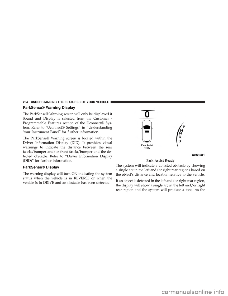
ParkSense® Display
The warning display will turn ON indicating the system
status when the vehicle is in REVERSE or when the
vehicle is in DRIVE and an obstacle has been detected.
The system will indicate a detected obstacle by showing
a single arc in the left and/or right rear regions based on
the object’s distance and location relative to the vehicle.
If an object is detected in the left and/or right rear region,
the display will show a single arc in the left and/or right
rear region and the system will produce a tone. As the
Park Assist Ready
234 UNDERSTANDING THE FEATURES OF YOUR VEHICLE
Page 240 of 717
Front Park Assist Audible Alerts
ParkSense® will turn off the Front Park Assist audible
alert (chime) after approximately 3 seconds when an
obstacle has been detected, the vehicle is stationary, and
brake pedal is applied.
Adjustable Chime Volume Settings
Front and Rear chime volume settings can be selected
from the Uconnect® System. Refer to#Uconnect® Set-
tings” in “Understanding Your Instrument Panel” for
further information.
The chime volume settings include LOW, MEDIUM, and
HIGH. The factory default volume setting is MEDIUM.
ParkSense® will retain its last known configuration state
through ignition cycles.
Enabling And Disabling ParkSense®
ParkSense® can be enabled and disabled with the
ParkSense® switch.
When the ParkSense® switch is pressed to disable
the system, the instrument cluster will display the
“PARKSENSE OFF” message for approximately
five seconds. Refer to “Driver Information Dis-
play (DID)” in “Understanding Your Instrument Panel” for
further information. When the shift lever/gear selector is
moved to REVERSE and the system is disabled, the DID will
display the “PARKSENSE OFF” message for as long as the
vehicle is in REVERSE.
The ParkSense® switch LED will be ON when
ParkSense® is disabled or requires service. The
ParkSense® switch LED will be OFF when the system is
enabled. If the ParkSense® switch is pressed, and the
system requires service, the ParkSense® switch LED will
blink momentarily, and then the LED will be ON.
238 UNDERSTANDING THE FEATURES OF YOUR VEHICLE
Page 245 of 717

PARKVIEW® REAR BACK UP CAMERA — IF
EQUIPPED
Your vehicle may be equipped with the ParkView® Rear
Back Up Camera that allows you to see an on-screen
image of the rear surroundings of your vehicle whenever
the shift lever/gear selector is put into REVERSE. The
image will be displayed on the Navigation/Multimedia
radio display screen along with a caution note to “check
entire surroundings” across the top of the screen. After
five seconds this note will disappear. The ParkView®
camera is located on the rear of the vehicle above the rear
License plate.
When the vehicle is shifted out of REVERSE (with camera
delay turned OFF), the rear camera mode is exited and
the navigation or audio screen appears again.
When the vehicle is shifted out of REVERSE (with camera
delay turned ON), the rear view image with dynamic
grid lines will be displayed for up to 10 seconds after
shifting out of#REVERSE#unless the forward vehicle
speed exceeds 8 mph (13 km/h), the transmission is
shifted into#PARK#or the ignition is switched to the OFF
position.
NOTE:The ParkView® Rear Back Up Camera has pro-
grammable modes of operation that may be selected
through the Uconnect® System. Refer to “Uconnect®
Settings” in “Understanding Your Instrument Panel” for
further information.
When enabled, active guide lines are overlaid on the
image to illustrate the width of the vehicle and its
projected backup path based on the steering wheel
position. The active guide lines will show separate zones
that will help indicate the distance to the rear of the
vehicle while a dashed center-line will indicate the center
3
UNDERSTANDING THE FEATURES OF YOUR VEHICLE 243