Page 345 of 717
time with GPS” button on the touchscreen until a check-
mark appears next to the setting, showing that setting has
been selected. Press the back arrow button on the touch-
screen to return to the previous menu.
•Set Time Hours
This feature will allow you to adjust the hours. The “Sync
time with GPS” button on the touchscreen must be
unchecked. To make your selection, press the “+” or “–”
buttons on the touchscreen to adjust the hours up or
down. Press the back arrow button on the touchscreen to
return to the previous menu.
•Set Time Minutes
This feature will allow you to adjust the minutes. The
“Sync time with GPS” button on the touchscreen must be
unchecked. To make your selection, press the “+” or “–”
buttons on the touchscreen to adjust the minutes up or
down. Press the back arrow button on the touchscreen to
return to the previous menu.
•Time Format
This feature will allow you to select the time format
display setting. Press the “Time Format” button on the
touchscreen until a check-mark appears next to the
“12hrs” or “24hrs” setting, showing that setting has been
selected. Press the back arrow button on the touchscreen
to return to the previous menu.
•Show Time In Status Bar — If Equipped
This feature will allow you to turn on or shut off the
digital clock in the status bar. To change the Show Time
Status setting press the “Show Time in Status Bar” button
on the touchscreen until a check-mark appears next to
setting, indicating that the setting has been selected. Press
the back arrow button on the touchscreen to return to the
previous menu.
4
UNDERSTANDING YOUR INSTRUMENT PANEL 343
Page 360 of 717
SiriusXM Setup — If Equipped
After pressing the “SiriusXM Setup” button on the touch-
screen, the following settings will be available:
•Channel Skip
SiriusXM can be programmed to designate a group of
channels that are the most desirable to listen to or to
exclude undesirable channels while scanning. To make
your selection, press the “Channel Skip” button on the
touchscreen, select the channels you would like to skip
followed by pressing the back arrow button on the
touchscreen.
•Subscription Information
New vehicle purchasers or lessees will receive a free
limited time subscription to SiriusXM Satellite Radio
with your radio. Following the expiration of the free
services, it will be necessary to access the information on
the Subscription Information screen to re-subscribe.
Press the “Subscription Info” button on the touchscreen
to access the Subscription Information screen.
Write down the SIRIUS ID numbers for your receiver. To
reactivate your service, either call the number listed on
the screen or visit the provider online.
NOTE:SiriusXM Travel Link is a separate subscription
and is available for U.S. residents only.
Restore Settings
After pressing the “Restore Settings” button on the
touchscreen the following settings will be available:
•Restore Settings
When this feature is selected it will reset the Display,
Clock, Audio, and Radio Settings to their default settings.
To restore the settings to their default setting, press the
Restore Settings button. A pop-up will appear asking
#Are you sure you want to reset your settings to default?”
358 UNDERSTANDING YOUR INSTRUMENT PANEL
Page 391 of 717
the passenger temperature setting with the driver tem-
perature setting. Changing the passenger temperature
setting while in Sync will automatically exit this feature.
10. Blower Control
Blower control is used to regulate the amount of air
forced through the climate system. There are seven
blower speeds available. Adjusting the blower will cause
automatic mode to switch to manual operation. The
speeds can be selected using either the blower control
knob on the faceplate or buttons on the touchscreen as
follows:
Blower Control Knob On The Faceplate
The blower speed increases as you turn the blower
control knob clockwise from the lowest blower setting.
The blower speed decreases as you turn the blower
control knob counterclockwise.
Button On The Touchscreen
Use the small blower icon to reduce the blower setting
and the large blower icon to increase the blower setting.
Blower can also be selected by pressing the blower bar
area between the icons.
11. Modes
The airflow distribution mode can be adjusted so air
comes from the instrument panel outlets, floor outlets,
and demist outlets. The Mode settings are as follows:
•Panel Mode
Air comes from the outlets in the instrument
panel. Each of these outlets can be individu-
ally adjusted to direct the flow of air. The air vanes of
the center outlets and outboard outlets can be moved
up and down or side to side to regulate airflow
direction. There is a shut off wheel located below the
air vanes to shut off or adjust the amount of airflow
from these outlets.
4
UNDERSTANDING YOUR INSTRUMENT PANEL 389
Page 549 of 717
NOTE:The trailer tongue weight must be considered as
part of the combined weight of occupants and cargo, and
should never exceed the weight referenced on the Tire
and Loading Information placard. Refer to “Tire Safety
Information” in “Starting and Operating” for further
information. The addition of passengers and cargo may
require reducing trailer tongue load and Gross Trailer
Weight (GTW). Redistributing cargo (to the trailer) may
be necessary to avoid exceeding Rear Gross Axle Weight
Rating (GAWR) of 3,700 lbs (1 678 kg).
Trailer Hitch Receiver Cover Removal (Summit
Models) — If Equipped
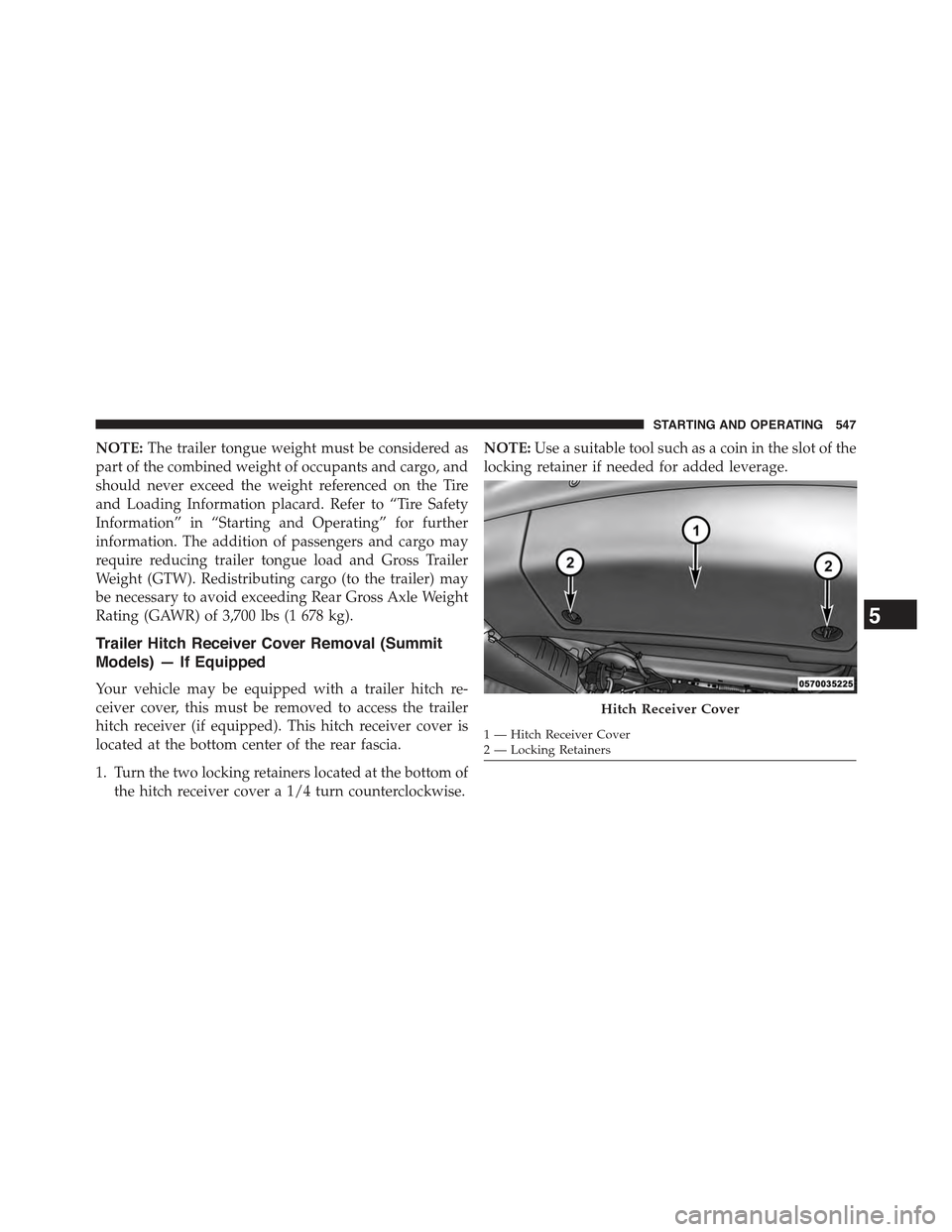
Your vehicle may be equipped with a trailer hitch re-
ceiver cover, this must be removed to access the trailer
hitch receiver (if equipped). This hitch receiver cover is
located at the bottom center of the rear fascia.
1. Turn the two locking retainers located at the bottom of
the hitch receiver cover a 1/4 turn counterclockwise.
NOTE:Use a suitable tool such as a coin in the slot of the
locking retainer if needed for added leverage.
Hitch Receiver Cover
1 — Hitch Receiver Cover2 — Locking Retainers
5
STARTING AND OPERATING 547
Page 581 of 717
6. Raise the vehicle by turning the jack screw clockwise.
Raise the vehicle only until the tire just clears the
surface and enough clearance is obtained to install the
spare tire. Minimum tire lift provides maximum sta-
bility.
WARNING!
Raising the vehicle higher than necessary can make
the vehicle less stable. It could slip off the jack and
hurt someone near it. Raise the vehicle only enough
to remove the tire.
7. Remove the lug nuts and wheel.
8. Position the spare wheel/tire on the vehicle and install
the lug nuts with the cone-shaped end toward the
wheel. Lightly tighten the nuts.
CAUTION!
Be sure to mount the spare tire with the valve stem
facing outward. The vehicle could be damaged if the
spare tire is mounted incorrectly.
Rear Jacking Location6
WHAT TO DO IN EMERGENCIES 579
Page 582 of 717
WARNING!
To avoid the risk of forcing the vehicle off the jack,
do not tighten the lug nuts fully until the vehicle has
been lowered. Failure to follow this warning may
result in personal injury.
9. Lower the vehicle by turning the jack screw counter-
clockwise, and remove the jack and wheel blocks.
10. Finish tightening the lug nuts. Push down on the
wrench while at the end of the handle for increased
leverage. Tighten the lug nuts in a star pattern until
each nut has been tightened twice. For correct lug nut
torque refer to Torque Specifications in this section. If
in doubt about the correct tightness, have them
checked with a torque wrench by your authorized
dealer or at a service station.
11. Lower the jack to the fully closed position and return
it and the tools to the proper positions in the foam
tray.
12. Remove the small center cap and securely store the
road wheel in the cargo area.
Mounting Spare Tire
580 WHAT TO DO IN EMERGENCIES
Page 584 of 717
WARNING!
To avoid the risk of forcing the vehicle off the jack,
do not tighten the lug nuts fully until the vehicle has
been lowered. Failure to follow this warning may
result in personal injury.
3. Lower the vehicle to the ground by turning the jack
handle counterclockwise.
4. Refer to Torque Table for proper lug nut torque.
5. After 25 miles (40 km) check the lug nut torque with a
torque wrench to ensure that all lug nuts are properly
seated against the wheel.
JUMP-STARTING
If your vehicle has a discharged battery it can be jump-
started using a set of jumper cables and a battery in
another vehicle or by using a portable battery booster
pack. Jump-starting can be dangerous if done improperly
so please follow the procedures in this section carefully.
WARNING!
Do not attempt jump-starting if the battery is frozen.
It could rupture or explode and cause personal injury.
CAUTION!
Do not use a portable battery booster pack or any
other booster source with a system voltage greater
than 12 Volts or damage to the battery, starter motor,
alternator or electrical system may occur.
582 WHAT TO DO IN EMERGENCIES
Page 665 of 717

WARNING!
A transient high voltage occurs at the bulb sockets of
High Intensity Discharge (HID) headlamps when the
headlamp switch is turned ON. It may cause serious
electrical shock or electrocution if not serviced prop-
erly. See your authorized dealer for service.
NOTE:On vehicles equipped with High Intensity Dis-
charge (HID) headlamps, when the headlamps are
turned on, there is a blue hue to the lamps. This dimin-
ishes and becomes more white after approximately 10
seconds, as the system charges.
Halogen Headlamps — If Equipped
1. Open the hood.
2. Turn the low or high beam bulb one–quarter turn
counterclockwise to remove from housing.
3. Disconnect the electrical connector and replace the
bulb.
CAUTION!
Do not touch the new bulb with your fingers. Oil
contamination will severely shorten bulb life. If the
bulb comes in contact with any oily surface, clean the
bulb with rubbing alcohol.
Front Turn Signal
1. Open the hood.
2. Turn the turn signal bulb one–quarter turn counter-
clockwise to remove from housing.
3. Disconnect the electrical connector and replace the
bulb.
7
MAINTAINING YOUR VEHICLE 663