Page 475 of 717
In the event power assist is lost for any reason (i.e.,
repeated brake applications with the engine off) the
brakes will still function. However, the effort required to
brake the vehicle will be much greater than that required
with the power system operating.
ELECTRONIC BRAKE CONTROL SYSTEM
Your vehicle is equipped with an advanced electronic
brake control system that includes the Anti-Lock Brake
System (ABS), Traction Control System (TCS), Brake
Assist System (BAS), Electronic Roll Mitigation (ERM),
and Electronic Stability Control (ESC). All five of these
systems work together to enhance vehicle stability and
control in various driving conditions.
Also, your vehicle may be equipped with Trailer Sway
Control (TSC), Hill Start Assist (HSA), Ready Alert
Braking (RAB), Rain Brake Support (RBS) and, if it has
four-wheel drive with the MP 3023 two-speed transfer
case, Hill Descent Control (HDC), Selec Speed Control
(SSC).
Anti-Lock Brake System (ABS)
The Anti-Lock Brake System (ABS) is designed to aid the
driver in maintaining vehicle control under adverse
braking conditions. The system operates with a separate
computer to modulate hydraulic pressure to prevent
wheel lock-up and help avoid skidding on slippery
surfaces.
All vehicle wheels and tires must be the same size and
type, and tires must be properly inflated to produce
accurate signals for the computer.
5
STARTING AND OPERATING 473
Page 476 of 717
WARNING!
Significant over or under-inflation of tires, or mixing
sizes of tires or wheels on the vehicle can lead to loss
of braking effectiveness.
The Anti-Lock Brake System conducts a low speed self-
test at about 12 mph (20 km/h). If for any reason your
foot is on the brake when the vehicle reaches 12 mph
(20 km/h), this check will be delayed until 25 mph
(40 km/h).
The Anti-Lock Brake System pump motor runs during
the self-test, and during an ABS stop, to provide the
regulated hydraulic pressure. The motor pump makes a
low humming noise during operation; this is normal.
WARNING!
•Pumping of the Anti-Lock Brakes will diminish
their effectiveness and may lead to a collision.
Pumping makes the stopping distance longer. Just
press firmly on your brake pedal when you need to
slow down or stop.
•The Anti-Lock Brake System (ABS) cannot prevent
the natural laws of physics from acting on the
vehicle, nor can they increase braking or steering
efficiency beyond that afforded by the condition of
the vehicle brakes and tires or the traction afforded.
•The ABS cannot prevent collisions, including those
resulting from excessive speed in turns, following
another vehicle too closely, or hydroplaning.
•The capabilities of an ABS-equipped vehicle must
never be exploited in a reckless or dangerous
manner which could jeopardize the user’s safety or
the safety of others.
474 STARTING AND OPERATING
Page 477 of 717
CAUTION!
The Anti-Lock Brake System is subject to possible
detrimental effects of electronic interference caused
by improperly installed aftermarket radios or tele-
phones.
NOTE:During severe braking conditions, a pulsing sen-
sation may occur and a clicking noise will be heard. This
is normal, indicating that the Anti-Lock Brake System is
functioning.
Traction Control System (TCS)
This system monitors the amount of wheel spin of each of
the driven wheels. If wheel spin is detected, brake
pressure is applied to the slipping wheel(s) and engine
power is reduced to provide enhanced acceleration and
stability.
A feature of the TCS system, Brake Limited Differential
(BLD), functions similar to a limited-slip differential and
controls the wheel spin across a driven axle. If one wheel
on a driven axle is spinning faster than the other, the
system will apply the brake of the spinning wheel. This
will allow more engine torque to be applied to the wheel
that is not spinning. This feature remains active even if
ESC system is in the “Partial Off” mode. Refer to “Elec-
tronic Stability Control (ESC)” in this section for further
information.
Brake Assist System (BAS)
The BAS is designed to optimize the vehicle’s braking
capability during emergency braking maneuvers. The
system detects an emergency braking situation by sens-
ing the rate and amount of brake application and then
applies optimum pressure to the brakes. This can help
reduce braking distances. The BAS complements the
anti-lock brake system (ABS). Applying the brakes very
5
STARTING AND OPERATING 475
Page 537 of 717
Starting
The characteristics of E-85 fuel make it unsuitable for use
when ambient temperatures fall below 0°F (-18°C). In the
range of 0°F (-18°C) to 32°F (0°C), you may experience an
increase in the time it takes for your engine to start, and
a deterioration in driveability (sags and/or hesitations)
until the engine is fully warmed up.
NOTE:Use of the engine block heater (if equipped) is
beneficial for E-85 startability when the ambient tempera-
ture is less than 32°F (0°C).
Cruising Range
Because E-85 fuel contains less energy per gallon/liter
than gasoline, you will experience an increase in fuel
consumption. You can expect your miles per gallon
(mpg)/miles per liter and your driving range to decrease
by about 30%, compared to gasoline operation.
Replacement Parts
Many components in your Flexible Fuel Vehicle (FFV) are
designed to be compatible with ethanol. Always be sure
that your vehicle is serviced with correct ethanol com-
patible parts.
CAUTION!
Replacing fuel system components with non-ethanol
compatible components can damage your vehicle.
Maintenance
CAUTION!
Do not use ethanol mixture greater than 85% in your
vehicle. It will cause difficulty in cold starting and
may affect drivability.
5
STARTING AND OPERATING 535
Page 549 of 717
NOTE:The trailer tongue weight must be considered as
part of the combined weight of occupants and cargo, and
should never exceed the weight referenced on the Tire
and Loading Information placard. Refer to “Tire Safety
Information” in “Starting and Operating” for further
information. The addition of passengers and cargo may
require reducing trailer tongue load and Gross Trailer
Weight (GTW). Redistributing cargo (to the trailer) may
be necessary to avoid exceeding Rear Gross Axle Weight
Rating (GAWR) of 3,700 lbs (1 678 kg).
Trailer Hitch Receiver Cover Removal (Summit
Models) — If Equipped
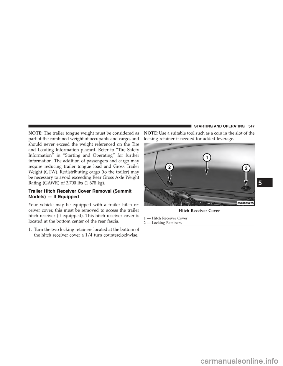
Your vehicle may be equipped with a trailer hitch re-
ceiver cover, this must be removed to access the trailer
hitch receiver (if equipped). This hitch receiver cover is
located at the bottom center of the rear fascia.
1. Turn the two locking retainers located at the bottom of
the hitch receiver cover a 1/4 turn counterclockwise.
NOTE:Use a suitable tool such as a coin in the slot of the
locking retainer if needed for added leverage.
Hitch Receiver Cover
1 — Hitch Receiver Cover2 — Locking Retainers
5
STARTING AND OPERATING 547
Page 553 of 717
WARNING!(Continued)
•Vehicles with trailers should not be parked on a
grade. When parking, apply the parking brake on
the tow vehicle. Put the tow vehicle transmission in
PARK. For four-wheel drive vehicles, make sure
the transfer case is not in NEUTRAL. Always,
block or'chock'the trailer wheels.
•GCWR must not be exceeded.
•Total weight must be distributed between the tow
vehicle and the trailer such that the following four
ratings are not exceeded:
1. GVWR
2. GTW
3. GAWR
4. Tongue weight rating for the trailer hitch uti-
lized.
Towing Requirements — Tires
•Do not attempt to tow a trailer while using a compact
spare tire.
•Proper tire inflation pressures are essential to the safe
and satisfactory operation of your vehicle. Refer to
“Tires – General Information” in “Starting And Oper-
ating” for proper tire inflation procedures.
•Check the trailer tires for proper tire inflation pres-
sures before trailer usage.
•Check for signs of tire wear or visible tire damage
before towing a trailer. Refer to “Tires – General
Information” in “Starting And Operating” for the
proper inspection procedure.
•When replacing tires, refer to “Tires – General Infor-
mation” in “Starting And Operating” for the proper
5
STARTING AND OPERATING 551
Page 576 of 717
1. Park the vehicle on a firm, level surface. Avoid ice or
slippery surfaces.
WARNING!
Do not attempt to change a tire on the side of the
vehicle closest to moving traffic, pull far enough off
the road to avoid being hit when operating the jack
or changing the wheel.
2. Turn on the Hazard Warning flasher.
3. Set the parking brake.
4. Place the shift lever into PARK.
5. Turn the ignition OFF.
6. Block both the front and rear of the
wheel diagonally opposite of the
jacking position. For example, if
changing the right front tire, block
the left rear wheel.
NOTE:Passengers should not remain in the vehicle
when the vehicle is being jacked.
7. For vehicles equipped with Quadra-Lift® refer to
“Quadra-Lift® — If Equipped” in “Starting And Op-
erating” for further information on disabling auto-
matic leveling.
574 WHAT TO DO IN EMERGENCIES
Page 581 of 717
6. Raise the vehicle by turning the jack screw clockwise.
Raise the vehicle only until the tire just clears the
surface and enough clearance is obtained to install the
spare tire. Minimum tire lift provides maximum sta-
bility.
WARNING!
Raising the vehicle higher than necessary can make
the vehicle less stable. It could slip off the jack and
hurt someone near it. Raise the vehicle only enough
to remove the tire.
7. Remove the lug nuts and wheel.
8. Position the spare wheel/tire on the vehicle and install
the lug nuts with the cone-shaped end toward the
wheel. Lightly tighten the nuts.
CAUTION!
Be sure to mount the spare tire with the valve stem
facing outward. The vehicle could be damaged if the
spare tire is mounted incorrectly.
Rear Jacking Location6
WHAT TO DO IN EMERGENCIES 579