Page 546 of 603
7-60
Maintenance
Main fuse
If the main fuse is blown, it must be
removed as follows:
1. Turn off the engine.
2. Disconnect the negative batterycable.
3. Remove the fuse panel cover by pressing the tab and pulling it up.
4. Remove the nuts shown in the pic- ture above.
5. Replace the fuse with a new one of the same rating.
6. Reinstall in the reverse order of removal.
Information
If the main fuse is blown, consult an
authorized HYUNDAI dealer.
Multi fuse
If the multi fuse is blown, it must be
removed as follows:
1. Turn off the engine.
2. Disconnect the negative battery
cable.
3. Remove the fuse panel cover by pressing the tab and pulling it up.
4. Remove the nuts shown in the pic- ture above.
5. Replace the fuse with a new one of the same rating.
6. Reinstall in the reverse order of removal.
Information
If the multi fuse is blown, consult an
authorized HYUNDAI dealer.
i
i
OLF074025OLF074026
Page 551 of 603
7-65
7
Maintenance
Engine compartment fuse panel
Inside the fuse/relay box cover, you
can find the fuse/relay label describ-
ing fuse/relay name and capacity.
Information
Not all fuse panel descriptions in this
manual may be applicable to your
vehicle; the information is accurate at
the time of printing. When you inspect
the fuse panel in your vehicle, refer to
the fuse panel label.
i
OLF074057N
OLF074028
Page 552 of 603
![Hyundai Sonata 2015 Owners Manual 7-66
Maintenance
Engine compartment main fuse panel
Fuse NameFuse rating Protected Component
MULTIFUSE
(TYPE A)
IG230A[Without Smart Key] Relay 8 (Start Relay), Ignition Switch,
[With Smart Key] Rela Hyundai Sonata 2015 Owners Manual 7-66
Maintenance
Engine compartment main fuse panel
Fuse NameFuse rating Protected Component
MULTIFUSE
(TYPE A)
IG230A[Without Smart Key] Relay 8 (Start Relay), Ignition Switch,
[With Smart Key] Rela](/manual-img/35/16796/w960_16796-551.png)
7-66
Maintenance
Engine compartment main fuse panel
Fuse NameFuse rating Protected Component
MULTIFUSE
(TYPE A)
IG230A[Without Smart Key] Relay 8 (Start Relay), Ignition Switch,
[With Smart Key] Relay 8 (Start Relay), PCB Block (IG2 Relay)
3 TCU40A[G4FJ - DCT] TCM
BLOWER40ARelay 3 (Blower Relay)
1 ABS40AESC Module
REAR HEATED50ARelay 1 (Rear Heated Relay)
1 B+50ASmart Junction Block (IPS2 (4CH), IPS3 (4CH), Fuse - F28/F29)
1 COOLING FAN50A[G4KH/G4FJ] Relay 11 (Cooling Fan Relay), [G4KJ] Relay 12 (Cooling Fan Relay)
2 COOLING FAN60A[G4KH/G4FJ] Relay 12 (Cooling Fan Relay)
1 MDPS80AMDPS Unit (Column Type)
MULTI FUSE
(TYPE B)
2 ABS30AESC Module, Multipurpose Check Connector
IG140A[Without Smart Key] Ignition Switch, [With Smart Key] PCB Block (IG1/ACC Relay)
4 TCU40A[G4FJ - DCT] TCM
3 POWER OUTLET40ARelay 5 (Power Outlet Relay)
2 B+50ASmart Junction Block (IPS1 (4CH), IPS4 (4CH), IPS5 (4CH), Fuse - F36)
5 B+60APCB Block (Engine Control Relay, Fuse - F4/F5/F6/F13/F14/F22)
1 B+60ASmart Junction Block (Power Window Relay, Fuse -
F1/F2/F3/F4/F10/F13/F17/F23/F24/F30)
2 MDPS100AMDPS Unit (Rack Type)
Page 553 of 603
7-67
7
Maintenance
Engine compartment main fuse panel
Fuse Name Fuse rating Protected Component
FUSE
3 E-CVVT20A[G4KJ/G4KH] PCM
2 E-CVVT20A[G4KJ/G4KH] PCM
DEICER20ARelay 5 (Deicer Relay)
H/LAMP HI20A[With HID] Relay 5 (Head Lamp High Relay)
1 VACUUM PUMP20A[G4KH/G4FJ] Vacuum Pump
1 E-CVVT40A[G4KJ/G4KH] Relay 9 (E-CVVT Relay)
4 B+40ASmart Junction Block (Leak Current Autocut Device Fuse - F15/F21/F22,
Fuse - F5/F6/F7/F12)
A/CON10AA/C Control Module
HEATED MIRROR10AECM (G4FJ), A/C Control Module, Drover/Passenger Power Outside Mirror
2 VACUUM PUMP10A[G4KH/G4FJ] Vacuum Pump
3 ECU10APCM/ECM
1 POWER OUTLET20ACigarette Lighter
FUEL PUMP20AFuel Pump Relay
HORN20AHorn Relay, ICM Relay Box (Burglar Alarm Horn Relay)
WIPER30AFront Wiper (Low) Relay, Front Wiper (High) Relay
2 TCU15ATransaxle Range Switch, TCM (G4FJ-DCT)
3 ABS10AESC Module, MDPS Unit
2 POWER OUTLET20ARear Power Outlet
Page 554 of 603
7-68
Maintenance
Engine compartment main fuse panel
Fuse Name Fuse rating Protected Component
FUSE
B/UP LAMP10ATransaxle Range Switch, PCM (G4KJ/G4KH-A/T), TCM (G4FJ-DCT), Audio,
Electro Chromic Mirror, Rear Combination Lamp (IN) LH/RH
1 SENSOR15AOxygen Sensor (Up/Down)
2 SENSOR15A
Purge Control Solenoid Valve, Canister Close Valve, RCV Control Solenoid Valve,
Fuel Pump Relay, E/R Junction Block (RLY. 12 - Cooling Fan 2 Relay),
[G4KJ/G4KH] Variable Intake Solenoid Valve, Oil Control Valve (Exhaust),
[G4FJ] Oil Control Valve #1/#2 (Intake/Exhaust)
1 ECU10APCM/ECM
1 TCU10APCM (G4KJ/G4KH-A/T), TCM (G4FJ-DCT)
1 ECU10APCM/ECM
IGN COIL20AIgnition Coil #1/#2/#3/#4, Condenser (G4FJ)
INJECTOR10A-
AMSBattery Sensor
Page 569 of 603

7-83
7
Maintenance
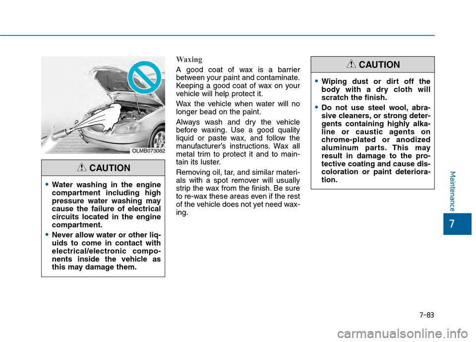
Waxing
A good coat of wax is a barrier
between your paint and contaminate.
Keeping a good coat of wax on your
vehicle will help protect it.
Wax the vehicle when water will no
longer bead on the paint.
Always wash and dry the vehicle
before waxing. Use a good quality
liquid or paste wax, and follow the
manufacturer’s instructions. Wax all
metal trim to protect it and to main-
tain its luster.
Removing oil, tar, and similar materi-
als with a spot remover will usually
strip the wax from the finish. Be sure
to re-wax these areas even if the rest
of the vehicle does not yet need wax-
ing.
OLMB073082
Water washing in the engine
compartment including high
pressure water washing may
cause the failure of electrical
circuits located in the engine
compartment.
Never allow water or other liq-
uids to come in contact with
electrical/electronic compo-
nents inside the vehicle as
this may damage them.
CAUTION
Wiping dust or dirt off the
body with a dry cloth will
scratch the finish.
Do not use steel wool, abra-
sive cleaners, or strong deter-
gents containing highly alka-
line or caustic agents on
chrome-plated or anodized
aluminum parts. This may
result in damage to the pro-
tective coating and cause dis-
coloration or paint deteriora-
tion.
CAUTION
Page 576 of 603

7-90
Maintenance
Canister
Fuel vapors generated inside the fuel
tank are absorbed and stored in the
onboard canister. When the engine is
running, the fuel vapors absorbed in
the canister are drawn into the surge
tank through the purge control sole-
noid valve.
Purge Control Solenoid Valve(PCSV)
The purge control solenoid valve is
controlled by the Engine Control
Module (ECM); when the engine
coolant temperature is low during
idling, the PCSV closes so that evap-
orated fuel is not taken into the
engine. After the engine warms-up
during ordinary driving, the PCSV
opens to introduce evaporated fuel to
the engine.
3. Exhaust Emission Control System
The Exhaust Emission Control
System is a highly effective system
which controls exhaust emissions
while maintaining good vehicle per-
formance.
When the engine starts or fails to
start, excessive attempts to restart
the engine may cause damage to the
emission system.
Vehicle modifications
This vehicle should not be modi-
fied. Modification of your vehicle
could affect its performance, safety
or durability and may even violate
governmental safety and emis-
sions regulations.
In addition, damage or performance
problems resulting from any modifi-
cation may not be covered under
warranty.
If you use unauthorized electronic devices, it may cause the vehicle to
operate abnormally, wire damage,
battery discharge and fire. For your
safety, do not use unauthorized
electronic devices.
Engine exhaust (carbon monox-ide) precautions
Carbon monoxide can be present
with other exhaust fumes. If you
smell exhaust fumes of any kind in
your vehicle, drive with all the win-
dows fully open. Have your vehicle
checked and repaired immediately.
Engine exhaust gases contain
carbon monoxide (CO). Though
colorless and odorless, it is
dangerous and could be lethal if
inhaled. Follow the instructions
on this page to avoid CO poi-
soning.
WARNING
Page 577 of 603

7-91
7
Maintenance
Do not operate the engine in con-fined or closed areas (such as
garages) any more than what is
necessary to move the vehicle in or
out of the area.
When the vehicle is stopped in an open area for more than a short
time with the engine running,
adjust the ventilation system (as
needed) to draw outside air into the
vehicle.
Never sit in a parked or stopped vehicle for any extended time with
the engine running.
When the engine stalls or fails to start, excessive attempts to restart
the engine may cause damage to
the emission control system.Operating precautions for cat-alytic converters (if equipped)
The exhaust system and cat-
alytic converter are very hot
during and immediately after
the engine has been running. To
avoid SERIOUS INJURY or
DEATH:
Do not park, idle, or drive the
vehicle over or near flamma-
ble objects, such as grass,
vegetation, paper, leaves, etc.
A hot exhaust system can
ignite flammable items under
your vehicle.
Keep away from the exhaust
system and catalytic convert-
er or you may get burned.
Also, Do not remove the heat
sink around the exhaust sys-
tem, do not seal the bottom of
the vehicle, and do not coat
the vehicle for corrosion con-
trol. It may present a fire risk
under certain conditions.
WARNING CALIFORNIA PROPOSITION 65
WARNING
Engine exhaust and a wide vari-
ety of automobile components
and parts, including compo-
nents found in the interior fur-
nishings in a vehicle, contain or
emit chemicals known to the
State of California to cause can-
cer and birth defects and repro-
ductive harm. In addition, cer-
tain fluids contained in vehicles
and certain products of compo-
nent wear contain or emit chem-
icals known to the State of
California to cause cancer and
birth defects or other reproduc-
tive harm.
WARNING