2015 HYUNDAI I40 wheel
[x] Cancel search: wheelPage 469 of 534

Downloaded from www.Manualslib.com manuals search engine Maintenance
64
7
Tire rotation
To equalize tread wear, it is recom-
mended that the tires be rotated
every 12,000 km (7,500 miles) or
sooner if irregular wear develops.
During rotation, check the tires for
correct balance.
When rotating tires, check for uneven
wear and damage. Abnormal wear is
usually caused by incorrect tire pres-
sure, improper wheel alignment, out-
of-balance wheels, severe braking or
severe cornering. Look for bumps or
bulges in the tread or side of tire.
Replace the tire if you find either of
these conditions. Replace the tire if
fabric or cord is visible. After rotation,
be sure to bring the front and rear tire
pressures to specification and check
lug nut tightness.
Refer to “Tire and wheels” in section
8.Disc brake pads should be inspected
for wear whenever tires are rotated.
✽ ✽ NOTICE
Rotate radial tires that have an
asymmetric tread pattern only from
front to rear and not from right to
left.
WARNING
Do not use the compact spare
tire for tire rotation.
Do not mix bias ply and radial ply tires under any circum-
stances. This may cause
unusual handling characteris-
tics that could result in death,
severe injury, or property
damage.
S2BLA790
S2BLA790A
CBGQ0707A
Without a spare tire With a full-size spare tire (if equipped)
Directional tires (if equipped)
Page 470 of 534

Downloaded from www.Manualslib.com manuals search engine 765
Maintenance
Wheel alignment and tire balance
The wheels on your vehicle were
aligned and balanced carefully at the
factory to give you the longest tire life
and best overall performance.
In most cases, you will not need to
have your wheels aligned again.
However, if you notice unusual tire
wear or your vehicle pulling one way
or the other, the alignment may need
to be reset.
If you notice your vehicle vibrating
when driving on a smooth road, your
wheels may need to be rebalanced.Tire replacement
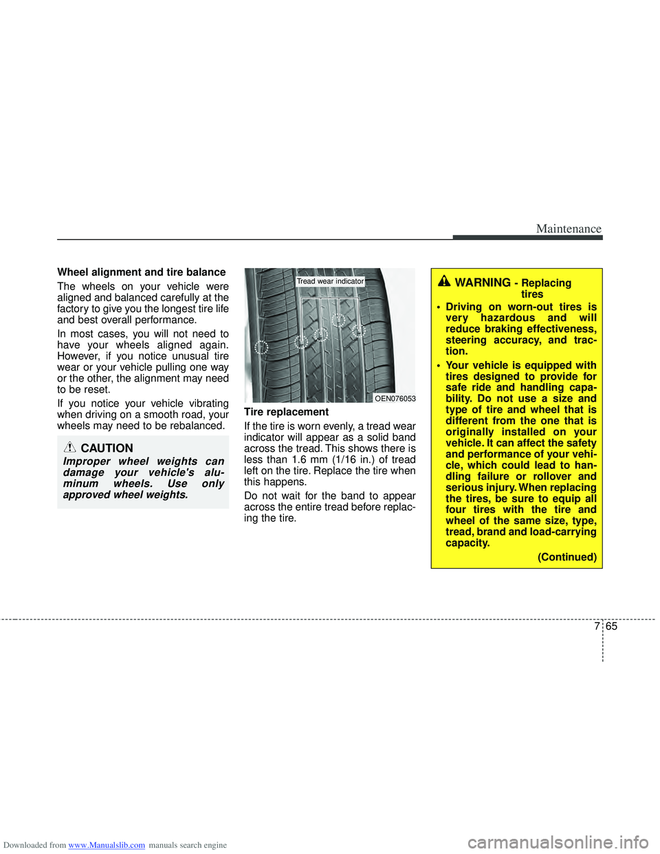
If the tire is worn evenly, a tread wear
indicator will appear as a solid band
across the tread. This shows there is
less than 1.6 mm (1/16 in.) of tread
left on the tire. Replace the tire when
this happens.
Do not wait for the band to appear
across the entire tread before replac-
ing the tire.
CAUTION
Improper wheel weights can
damage your vehicle's alu-minum wheels. Use onlyapproved wheel weights.
WARNING - Replacing tires
Driving on worn-out tires is very hazardous and will
reduce braking effectiveness,
steering accuracy, and trac-
tion.
Your vehicle is equipped with tires designed to provide for
safe ride and handling capa-
bility. Do not use a size and
type of tire and wheel that is
different from the one that is
originally installed on your
vehicle. It can affect the safety
and performance of your vehi-
cle, which could lead to han-
dling failure or rollover and
serious injury. When replacing
the tires, be sure to equip all
four tires with the tire and
wheel of the same size, type,
tread, brand and load-carrying
capacity.
(Continued)
OEN076053
Tread wear indicator
Page 471 of 534

Downloaded from www.Manualslib.com manuals search engine Maintenance
66
7
Compact spare tire replacement
(if equipped)
A compact spare tire has a shorter
tread life than a regular size tire.
Replace it when you can see the
tread wear indicator bars on the tire.
The replacement compact spare tire
should be the same size and design
tire as the one provided with your
new vehicle and should be mounted
on the same compact spare tire
wheel. The compact spare tire is not
designed to be mounted on a regular
size wheel, and the compact spare
tire wheel is not designed for mount-
ing a regular size tire. Wheel replacement
When replacing the metal wheels for
any reason, make sure the new
wheels are equivalent to the original
factory units in diameter, rim width
and offset.
(Continued)
The use of any other tire size
or type may seriously affect
ride, handling, ground clear-
ance, stopping distance, body
to tire clearance, snow tire
clearance, and speedometer
reliability.
It is best to replace all four tires at the same time. If that
is not possible, or necessary,
then replace the two front or
two rear tires as a pair.
Replacing just one tire can
seriously affect your vehicle’s
handling.
The ABS works by comparing the speed of the wheels. Tire
size can affect wheel speed.
When replacing tires, all 4
tires must use the same size
originally supplied with the
vehicle. Using tires of a differ-
ent size can cause the ABS
(Anti-lock Brake System) and
ESP (Electronic Stability
Program) (if equipped) to
work irregularly.
WARNING
A wheel that is not the correct
size may adversely affect wheel
and bearing life, braking and
stopping abilities, handling
characteristics, ground clear-
ance, body-to-tire clearance,
snow chain clearance,
speedometer and odometer cal-
ibration, headlight aim and
bumper height.
Page 472 of 534

Downloaded from www.Manualslib.com manuals search engine 767
Maintenance
Tire traction
Tire traction can be reduced if you
drive on worn tires, tires that are
improperly inflated or on slippery
road surfaces. Tires should be
replaced when tread wear indicators
appear. To reduce the possibility of
losing control, slow down whenever
there is rain, snow or ice on the road.
Tire maintenance
In addition to proper inflation, correct
wheel alignment helps to decrease
tire wear. If you find a tire is worn
unevenly, have your dealer check the
wheel alignment.
When you have new tires installed,
make sure they are balanced. This
will increase vehicle ride comfort and
tire life. Additionally, a tire should
always be rebalanced if it is removed
from the wheel.Tire sidewall labeling
This information identifies and
describes the fundamental charac-
teristics of the tire and also provides
the tire identification number (TIN)
for safety standard certification. The
TIN can be used to identify the tire in
case of a recall.
1. Manufacturer or brand name
Manufacturer or Brand name is
shown.
2. Tire size designation
A tire’s sidewall is marked with a tire
size designation. You will need this
information when selecting replace-
ment tires for your car. The following
explains what the letters and num-
bers in the tire size designation
mean.
Example tire size designation:
(These numbers are provided as an
example only; your tire size designa-
tor could vary depending on your
vehicle.)
205/60R16 92V
P - Applicable vehicle type (tires
marked with the prefix “P’’ are
intended for use on passenger
vehicles or light trucks; however,
not all tires have this marking).
205 - Tire width in millimeters.
60 - Aspect ratio. The tire’s section height as a percentage of its
width.
R - Tire construction code (Radial).
16 - Rim diameter in inches.
I030B04JM
1
1
23
4
5,6
7
Page 473 of 534

Downloaded from www.Manualslib.com manuals search engine Maintenance
68
7
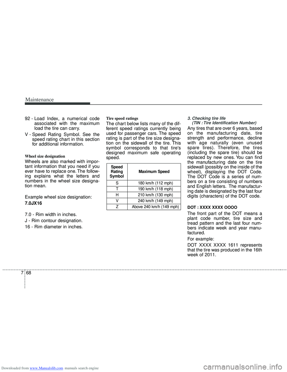
S 180 km/h (112 mph)
T 190 km/h (118 mph)
H 210 km/h (130 mph) V 240 km/h (149 mph)Z Above 240 km/h (149 mph)
Maximum Speed
Speed
Rating
Symbol
92 - Load Index, a numerical code associated with the maximum
load the tire can carry.
V - Speed Rating Symbol. See the speed rating chart in this section
for additional information.
Wheel size designation
Wheels are also marked with impor-
tant information that you need if you
ever have to replace one. The follow-
ing explains what the letters and
numbers in the wheel size designa-
tion mean.
Example wheel size designation:
7.0JX16
7.0 - Rim width in inches.
J - Rim contour designation.
16 - Rim diameter in inches.
Tire speed ratings
The chart below lists many of the dif-
ferent speed ratings currently being
used for passenger cars. The speed
rating is part of the tire size designa-
tion on the sidewall of the tire. This
symbol corresponds to that tire's
designed maximum safe operating
speed.
3. Checking tire life
(TIN : Tire Identification Number)
Any tires that are over 6 years, based
on the manufacturing date, tire
strength and performance, decline
with age naturally (even unused
spare tires). Therefore, the tires
(including the spare tire) should be
replaced by new ones. You can find
the manufacturing date on the tire
sidewall (possibly on the inside of the
wheel), displaying the DOT Code.
The DOT Code is a series of num-
bers on a tire consisting of numbers
and English letters. The manufactur-
ing date is designated by the last four
digits (characters) of the DOT code.
DOT : XXXX XXXX OOOO
The front part of the DOT means a
plant code number, tire size and
tread pattern and the last four num-
bers indicate week and year manu-
factured.
For example:
DOT XXXX XXXX 1611 represents
that the tire was produced in the 16th
week of 2011.
Page 475 of 534

Downloaded from www.Manualslib.com manuals search engine Maintenance
70
7
Traction - AA, A, B & C
The traction grades, from highest to
lowest, are AA, A, B and C. Those
grades represent the tires ability to
stop on wet pavement as measured
under controlled conditions on spec-
ified government test surfaces of
asphalt and concrete. A tire marked
C may have poor traction perform-
ance.
Temperature -A, B & C
The temperature grades are A (the
highest), B and C representing the
tire’s resistance to the generation of
heat and its ability to dissipate heat
when tested under controlled condi-
tions on a specified indoor laboratory
test wheel.
Sustained high temperature can
cause the material of the tire to
degenerate and reduce tire life, and
excessive temperature can lead to
sudden tire failure. Grades B and A
represent higher levels of perform-
ance on the laboratory test wheel
than the minimum required by the
law.
WARNING
The traction grade assigned to
this tire is based on straight-
ahead braking traction tests,
and does not include accelera-
tion, cornering, hydroplaning,
or peak traction characteristics.
WARNING - Tire
temperature
The temperature grade for this
tire is established for a tire that
is properly inflated and not
overloaded. Excessive speed,
underinflation, or excessive
loading, either separately or in
combination, can cause heat
build-up and possible sudden
tire failure. This can cause loss
of vehicle control and serious
injury or death.
Page 481 of 534

Downloaded from www.Manualslib.com manuals search engine Maintenance
76
7
Instrument panel (Driver’s side fuse panel)
No.Fuse ratingSymbol Fuse NameProtected component
120APOWER
OUTLET 2Console Power Outlet, Rear Power Outlet
230APOWER
TAIL GATEPower Tail Gate
310AMODULE 1Smart Key Control Module, BCM, Audio, AMP, JBL AMP, A/V & Navigation Head Unit,
DC-DC Converter (Audio/AMP), Over Head Console Lamp, Parking Guide System,
Power Outside Mirror Switch
410AMODULE 4E/R Fuse & Relay Box (RLY. 12), Stop Lamp Switch, Multipurpose Check Connector,
Active Air Flap Unit, Fuel Filter Warning Sensor (D4FD)
57.5AMODULE 3Smart Key Control Module, BCM, Panorama Sunroof, Rain Sensor,
Driver/Passenger CCS Control Module, ICM Relay Box (Headlamp Washer Relay)
615APOWER
OUTLET 1Front Power Outlet
720AP/SEAT PASSPassenger Manual Switch
810AHTD MIRRDriver/Passenger Power Outside Mirror, ECM/PCM, A/C Control Module
925AAMPAMP, JBL AMP, DC-DC Converter (AMP)
1025AWIPER FRTICM Relay Box (Rain Sensor Relay), Multifunction Switch,
E/R Fuse & Relay Box (RLY. 7), Front Wiper Motor
117.5AA/CONE/R Fuse & Relay Box (RLY. 4), EMS Box (Fuel Heater Relay),
Diesel Box (PTC Heater Relay #2/#3), A/C Control Module
1215ASTEERING
WHEEL HEATERSteering Wheel Heater
Page 494 of 534

Downloaded from www.Manualslib.com manuals search engine 789
Maintenance
5. To aim the low beam left or right, turnthe driver (1) clockwise or counter-
clockwise. To aim the low beam up or
down, turn the driver (2) clockwise or
counterclockwise.
To aim the high beam up or down, turnthe driver (3) clockwise or counter-
clockwise. AFLS type
1. Turn off the engine
2. Turn the light switch to the low beam
position.
3. Position the tires straight ahead with the steering wheel.
4. Turn on the engine.
5. Inflate the tires to the specified pres- sure and remove any loads from the
vehicle except the driver, spare tire,
and tools.
6. The vehicle should be placed on a flat floor.
7. Draw vertical lines (Vertical lines pass- ing through respective head lamp cen-
ters) and a horizontal line (Horizontal
line passing through center of head
lamps) on the screen.
8. With the head lamp and battery in nor- mal condition, aim the head lamps so
the brightest portion falls on the hori-
zontal and vertical lines.
9. To aim the low beam left or right, turn the driver (1) clockwise or counter-
clockwise. To aim the low beam up or
down, turn the driver (2) clockwise or
counterclockwise. To aim the high
beam up or down, turn the driver (3)
clockwise or counterclockwise.
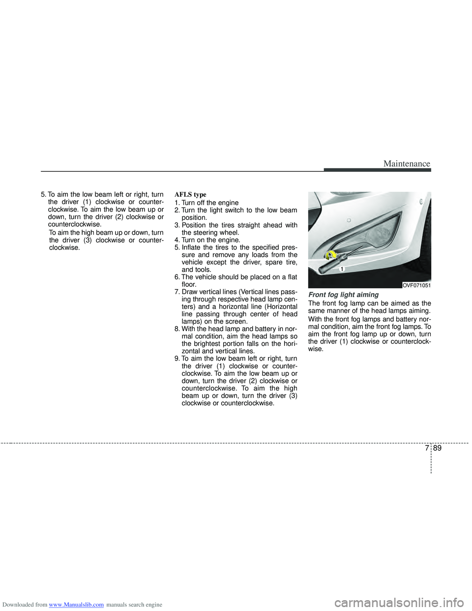
Front fog light aiming
The front fog lamp can be aimed as the
same manner of the head lamps aiming.
With the front fog lamps and battery nor-
mal condition, aim the front fog lamps. To
aim the front fog lamp up or down, turn
the driver (1) clockwise or counterclock-
wise.
OVF071051