2015 HYUNDAI I30 ABS
[x] Cancel search: ABSPage 378 of 635

761
Maintenance
Description Fuse rating Protected componentABS 10A ESP control module, ABS control module, Multi purpose check connector
ECU.2 10A Ignition coil #1,2,3,4(G4FC), PCM(G4GC)
B/UP 10A Back up lamp switch, Transaxle range switch, Cruise control module
H/LP LO RH 10A Head lamp(RH), Head lamp leveling actuator(RH)
Fuse H/LP LO LH 10A Head lamp(LH), Head lamp leveling actuator(LH), Head lamp leveling switch H/LP HI 20A Head lamp Hi relay
SNSR.1 10A Immobilizer module(G4FC/G4GC), Stop lamp switch(D4FB), Lambda sensor(D4FB) etc.
SPARE 10A (Spare)
SPARE 15A (Spare)
SPARE 20A (Spare)
Description Fuse rating Protected component
GLOW PLUG FUSIBLE LINK 80A Glow plug, Air heater
PTC HEATER #1 FUSIBLE LINK 50A PTC heater 1
PTC HEATER #2 FUSIBLE LINK 50A PTC heater 2
PTC HEATER #3 FUSIBLE LINK 50A PTC heater 3
FUEL FILTER HEATER FUSIBLE LINK 30A Fuel filter heater
GLOW PLUG RELAY - Glow plug relay
PTC HEATER RELAY #1 - PTC heater relay 1
PTC HEATER RELAY #2 - PTC heater relay 2
PTC HEATER RELAY #3 - PTC heater relay 3
FUEL FILTER HEATER RELAY - Fuel filter heater relay
Engine compartment (Diesel box)
Page 381 of 635

Maintenance
64
7
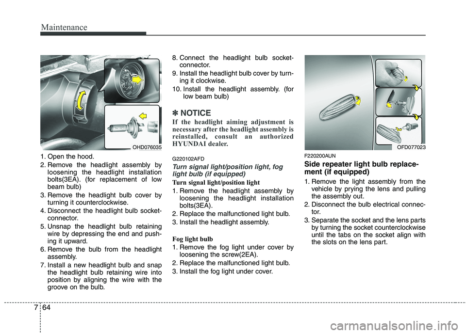
1. Open the hood.
2. Remove the headlight assembly by
loosening the headlight installation
bolts(3EA). (for replacement of low
beam bulb)
3. Remove the headlight bulb cover by turning it counterclockwise.
4. Disconnect the headlight bulb socket- connector.
5. Unsnap the headlight bulb retaining wire by depressing the end and push-
ing it upward.
6. Remove the bulb from the headlight assembly.
7. Install a new headlight bulb and snap the headlight bulb retaining wire into
position by aligning the wire with the
groove on the bulb. 8. Connect the headlight bulb socket-
connector.
9. Install the headlight bulb cover by turn- ing it clockwise.
10. Install the headlight assembly. (for low beam bulb)
✽✽NOTICE
If the headlight aiming adjustment is
necessary after the headlight assembly is
reinstalled, consult an authorized
HYUNDAI dealer.
G220102AFD
Turn signal light/position light, fog light bulb (if equipped)
Turn signal light/position light
1. Remove the headlight assembly by loosening the headlight installation bolts(3EA).
2. Replace the malfunctioned light bulb.
3. Install the headlight assembly.
Fog light bulb
1. Remove the fog light under cover by loosening the screw(2EA).
2. Replace the malfunctioned light bulb.
3. Install the fog light under cover. F220200AUN
Side repeater light bulb replace- ment (if equipped)
1. Remove the light assembly from the
vehicle by prying the lens and pulling
the assembly out.
2. Disconnect the bulb electrical connec- tor.
3. Separate the socket and the lens parts by turning the socket counterclockwise
until the tabs on the socket align with
the slots on the lens part.
OHD076035OFD077023
Page 383 of 635

Maintenance
66
7
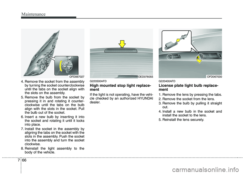
4. Remove the socket from the assembly
by turning the socket counterclockwise
until the tabs on the socket align with
the slots on the assembly.
5. Remove the bulb from the socket by pressing it in and rotating it counter-
clockwise until the tabs on the bulb
align with the slots in the socket. Pull
the bulb out of the socket.
6. Insert a new bulb by inserting it into the socket and rotating it until it locks
into place.
7. Install the socket in the assembly by aligning the tabs on the socket with the
slots in the assembly. Push the socket
into the assembly and turn the socket
clockwise.
8. Reinstall the light assembly to the body of the vehicle. G220500AFD High mounted stop light replace- ment
If the light is not operating, have the vehi-
cle checked by an authorized HYUNDAI
dealer.
G220400AFD
License plate light bulb replace- ment
1. Remove the lens by pressing the tabs.
2. Remove the socket from the lens.
3. Remove the bulb by pulling it straight
out.
4. Install a new bulb in the socket and install the socket to the lens.
5. Reinstall the lens securely.
OFD067027OED076055OFD067030
Page 384 of 635

767
Maintenance
G220600AUN
Interior light bulb replacement
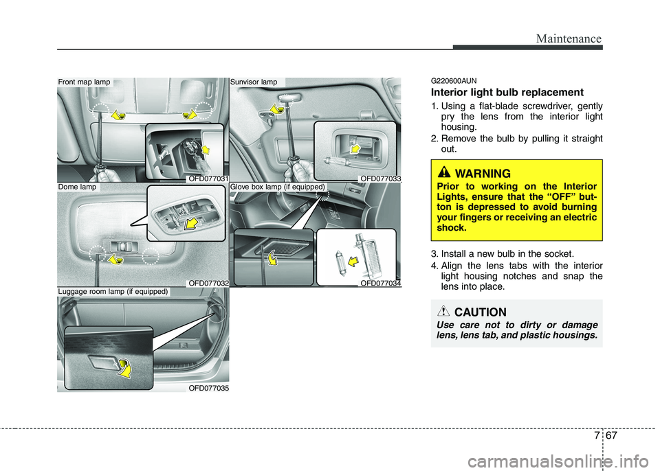
1. Using a flat-blade screwdriver, gentlypry the lens from the interior light housing.
2. Remove the bulb by pulling it straight out.
3. Install a new bulb in the socket.
4. Align the lens tabs with the interior light housing notches and snap the
lens into place.Front map lamp
Dome lamp
Sunvisor lamp
OFD077034
Glove box lamp (if equipped)
WARNING
Prior to working on the Interior
Lights, ensure that the “OFF” but-
ton is depressed to avoid burning
your fingers or receiving an electric
shock.
OFD077035
Luggage room lamp (if equipped)
CAUTION
Use care not to dirty or damage lens, lens tab, and plastic housings.
OFD077031
OFD077032
OFD077033
Page 391 of 635

Maintenance
74
7
EMISSION CONTROL SYSTEM
G270000AFD
The emission control system of your
vehicle is covered by a written limited
warranty. Please see the warranty infor-
mation contained in the Service Passport
in your vehicle.
Your vehicle is equipped with an emis- sion control system to meet all emission
regulations. There are three emission control sys-
tems which are as follows.
(1) Crankcase emission control system
(2) Evaporative emission control system(3) Exhaust emission control system In order to assure the proper function of
the emission control systems, it is rec-
ommended that you have your car
inspected and maintained by an author-
ized HYUNDAI dealer in accordance with
the maintenance schedule in this manu-al. Caution for the Inspection and
Maintenance Test (With Electronic
Stability Program (ESP) system)
To prevent the vehicle from misfir-
ing during dynamometer testing,
turn the Electronic Stability
Program (ESP) system off by press-
ing the ESP switch.
After dynamometer testing is com- pleted, turn the ESP system back on
by pressing the ESP switch again.
G270100AUN
1. Crankcase emission control system
The positive crankcase ventilation sys-
tem is employed to prevent air pollution
caused by blow-by gases being emitted
from the crankcase. This system supplies
fresh filtered air to the crankcase through
the air intake hose. Inside the crankcase,
the fresh air mixes with blow-by gases,
which then pass through the PCV valveinto the induction system. G270200AFD
2. Evaporative emission control
System
The Evaporative Emission Control
System is designed to prevent fuel
vapors from escaping into the atmos-
phere.
G270201AUN
Canister
Fuel vapors generated inside the fuel tank are absorbed and stored in the
onboard canister. When the engine is
running, the fuel vapors absorbed in the
canister are drawn into the surge tank
through the purge control solenoid valve.
G270202AUN
Purge Control Solenoid Valve (PCSV)
The purge control solenoid valve is con-
trolled by the Engine Control Module
(ECM); when the engine coolant temper-
ature is low during idling, the PCSV clos-
es so that evaporated fuel is not taken
into the engine. After the engine warms-
up during ordinary driving, the PCSV
opens to introduce evaporated fuel to the
engine.
Page 405 of 635

Index
2
I
Air bags ···········································································3-37
Air bag warning label................................................3-59
Air bag warning light ................................................3-56
Curtain air bag ..........................................................3-48
Driver's and passenger's front air bag ......................3-40
Side air bag................................................................3-46
Air cleaner·······································································7-33
Alarm system ····································································4-6
Antenna ·········································································4-103
Anti-lock brake system (ABS)········································5-20
Appearance care······························································7-68 Exterior care ······························································7-68
Interior care ·······························································7-73
Armrest ···········································································3-10
Ashtray ············································································4-92
Audio system ································································4-103 Antenna ···································································4-103
Aux, USB and iPod ···················································4-95
Steering wheel audio control ··································4-104
Automatic climate control system ··································4-76 Air conditioning ························································4-83
Automatic heating and air conditioning····················4-78
Manual heating and air conditioning ························4-79
Automatic transaxle ························································5-11 Ignition key interlock system ····································5-15
Shift lock system ·······················································5-15 Barrier net ·······································································4-98
Battery ·············································································7-40
Battery saver function ·····················································4-54
Before driving ···································································5-3
Bottle holders, see cup holders ·······································4-93
Brake system ···································································5-17
Anti-lock brake system (ABS) ··································5-20
Electronic stability program (ESP) ···························5-22
Parking brake·····························································5-18
Power brakes ·····························································5-17
Brakes/clutch fluid ··························································7-28
Bulb replacement ····························································7-62 Front fog light bulb replacement·······························7-64
Headlight bulb replacement ······································7-63
High mounted stop light replacement ·······················7-66
Interior light bulb replacement··································7-67
License plate light bulb replacement ························7-66
Position light bulb replacement·································7-64
Rear combination light bulb replacement ·················7-65
Side repeater light bulb replacement·························7-64
Turn signal light bulb replacement ···························7-64
Bulb wattage ·····································································9-2
AB
Page 448 of 635

335
Safety system of your vehicle
To secure the child restraint seat
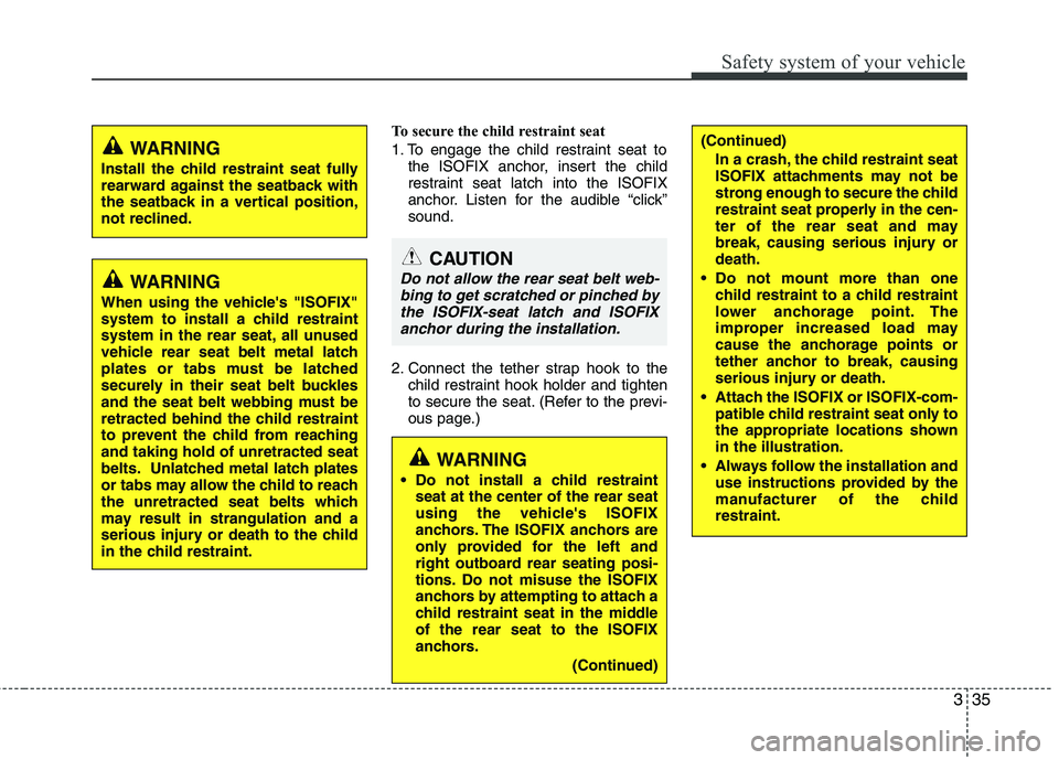
1. To engage the child restraint seat tothe ISOFIX anchor, insert the child
restraint seat latch into the ISOFIX
anchor. Listen for the audible “click”sound.
2. Connect the tether strap hook to the child restraint hook holder and tighten
to secure the seat. (Refer to the previ-
ous page.)
WARNING
Do not install a child restraint seat at the center of the rear seat
using the vehicle's ISOFIX
anchors. The ISOFIX anchors are
only provided for the left and
right outboard rear seating posi-
tions. Do not misuse the ISOFIX
anchors by attempting to attach a
child restraint seat in the middleof the rear seat to the ISOFIX
anchors.
(Continued)
WARNING
When using the vehicle's "ISOFIX"
system to install a child restraint
system in the rear seat, all unused
vehicle rear seat belt metal latch
plates or tabs must be latched
securely in their seat belt buckles
and the seat belt webbing must be
retracted behind the child restraint
to prevent the child from reachingand taking hold of unretracted seat
belts. Unlatched metal latch plates
or tabs may allow the child to reach
the unretracted seat belts which
may result in strangulation and a
serious injury or death to the child
in the child restraint.
WARNING
Install the child restraint seat fully
rearward against the seatback with
the seatback in a vertical position,
not reclined.(Continued)
In a crash, the child restraint seat
ISOFIX attachments may not be
strong enough to secure the child
restraint seat properly in the cen-
ter of the rear seat and may
break, causing serious injury ordeath.
Do not mount more than one child restraint to a child restraint
lower anchorage point. The
improper increased load may
cause the anchorage points or
tether anchor to break, causing
serious injury or death.
Attach the ISOFIX or ISOFIX-com- patible child restraint seat only to
the appropriate locations shownin the illustration.
Always follow the installation and use instructions provided by the
manufacturer of the childrestraint.
CAUTION
Do not allow the rear seat belt web-
bing to get scratched or pinched bythe ISOFIX-seat latch and ISOFIX anchor during the installation.
Page 463 of 635

Safety system of your vehicle
50
3
C040801AUN
Air bag inflation conditions
Front air bag
Front air bags are designed to inflate in a frontal collision depending on the intensi-
ty, speed or angles of impact of the frontcollision.
OED036096
WARNING
Do not hit or allow any objects to impact the locations where air bag
or sensors are installed.
This may cause unexpected air
bag deployment, which could
result in serious personal injuryor death.
If the installation location or angle of the sensors is altered in
any way, the air bags may deploy
when they should not or they may
not deploy when they should,
causing severe injury or death.
Therefore, do not try to perform
maintenance on or around the air
bag sensors. Have the vehicle
checked and repaired by an
authorized HYUNDAI dealer.
(Continued)(Continued)
Problems may arise if the sensorinstallation angles are changed
due to the deformation of the
front bumper, body or B pillar
where side collision sensors are
installed. Have the vehicle
checked and repaired by an
authorized HYUNDAI dealer.
Your vehicle has been designed to absorb impact and deploy the
air bag(s) in certain collisions.
Installing aftermarket bumper
guards or replacing a bumper
with non-genuine parts may
adversely affect your vehicles
collision and air bag deployment
performance.